3.0 engine rebuild and re-install FAQ
#1
 02-24-2009, 04:41 PM

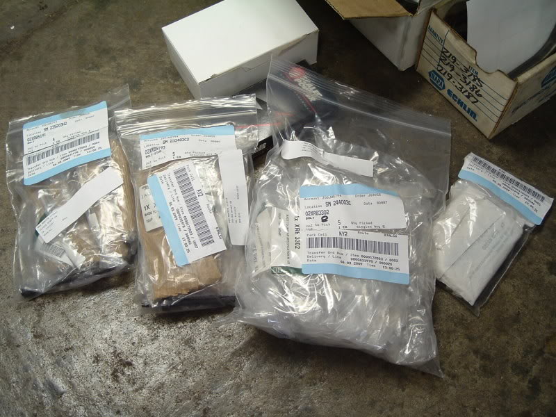
Today, I would like to open a thread to invite ANYONE to post their experiences with the 3.0 Duratec engine in our x-type Jaguar. We have already been through the removal phase and the tear down phase is pretty straight forward. Currently I have my block ready to go to the machine/mechanic shop to have it vated, (cleaned out using a chemical and pressured through ALL oil gallies) this is to make sure there are no remnants of fine metal shavings left in the block. They will then mic and polish the crank, install new thrust bearings, install new rod bearings, de-glaze the cylinders and install new rings and locate a hole for an oil pressure gauge. The cost is not too bad at all. I have also decided to do some EXTRA work while everything is out of there. I have removed the half-shafts and wheel hubs. I am going to send the hubs out and have them powder coated black and have new bearings pressed in. I will also have my new crossed and drilled rotors black powder coated in the veins and wheel hub, front and back, but obviously not the surface the brakes ride on. I am also taking the time to send out the valve covers, front cover and plenum out to be polished. I will have the plenum black powder coat, the valve covers and the plenum will get a durable clear coat. Then the exhaust will also get attention. I will ceramic coat the oil pan and the exhaust down to the collector at the back of the engine compartment. When the block gets back I will paint it racing green. Over all I think this car will then be MINE! While all that is at the various trades I will work on the heads and right now do not know if I need to get a shop involved yet or not. The valves look pretty clean and the seats are still new looking so I don't think it needs to be "touched" and re-assembled. I already have several hundred dollars of gaskets and o-rings on order, included in that order are 24 valve stem seals. I don't know yet how to compress the spring since it is in a hole. I will need to do some homework on this. After the heads I will move to the Transmission and the infamous Transfer Case. I plan to drain the Transmission and remove the Pan to check the filter, if there is one. I will also need to find a suitable location for the new Transmission Temp Gauge. Then the Transfer Case. The TC "fill" plug is on top of the unit with one of the Tranny bolts right over the top of it covering it about 1/4 of its diameter. I wanted to put in a plumbing elbow and run pipe to the top of the engine compartment for easy drain and fill. We will see how this works out. I would also like to outfit the Tranny with a simple dip stick to check it's levels and for easy filling. The above 2 custom options may just be a "pipe" dream, know what I mean? Something I would like to do but haven't spent enough time exploring the possibilities. After the TC I will replace the seals on the Tranny and TC and then re-lube my CV joints and install new rubber boots. I will also put new rubber on the Tie-Rod and Lower Arm ball joints with fresh lube. My goal is 75,000 more trouble free miles. When the Drive shaft goes back in I will have re-greased the center bearing since I have heard the infamous "whining" in very cold temperatures. I only have 49 pics left in my albums on this site and will probably need to find a storage place somewhere else. Stay tuned for this awesome adventure into this "FUN" driving machine. Here is the beginning of this project. The Engine Parts list with part numbers and average cost at dealer. I DID NOT PRICE these parts from your dealer but from the ALLDATA information I had and it was pretty spot on with what I paid at http://www.jpamporschejaguarparts.com and my local dealer.
310jag, I hope you will also help with this thread.


310jag, I hope you will also help with this thread.
#2
02-24-2009, 06:48 PM

Join Date: Mar 2008
Location: Powell, Ohio U.S.A. 43065
Posts: 2,521
Likes: 0
Received 70 Likes
on
56 Posts
Best make sure you can get oversize bearings before you do anything: the other guy put up a picture of a wiped crankshaft, and you can't cut a 4.0 crank and get bearings for it. I would guess the situation is the same for 3.0: there isn't anything in the reprint above to indicate the availability of oversize bearings.
Cranks that are candidates for polishing don't really need it, and cranks that are visibly scored or cooked won't polish. So you will need a crank, or a good used engine.
Cranks that are candidates for polishing don't really need it, and cranks that are visibly scored or cooked won't polish. So you will need a crank, or a good used engine.
#3
02-26-2009, 06:52 PM

#4
02-26-2009, 07:15 PM
Join Date: Mar 2008
Location: Powell, Ohio U.S.A. 43065
Posts: 2,521
Likes: 0
Received 70 Likes
on
56 Posts
Valid point that I'm glad you raised, and add to that straightening (after the weld and before the cut) and possibly heat treating , and that all will take alot more than $225 U.S. in my neighborhood.
On an unrelated note, who in the world builds a $30,000 car with a set of pistons that cost $2400?
On an unrelated note, who in the world builds a $30,000 car with a set of pistons that cost $2400?
The following users liked this post:
Panthro (05-10-2019)
#5
03-11-2009, 12:47 PM
Rebuilding the Ford 3.0L
http://www.enginebuildermag.com/Article/1142/rebuilding_the_ford_30l.aspxBy Roy Berndt
From the standpoint of customer satisfaction, the Ford Duratec engines have rapidly become Ford's finest engine launch in history. The engine ranked second in J.D. Power & Associates' satisfaction survey for 1996 and boasts zero claims against oil consumption.
This is a great place to get familiar with your engine. You may find yourself, like me, trying to find a gasket or pump or o-ring and cannot find a Jaguar supplied part. Well, with the correct information you can go to Ford/Lincoln and order the parts at a fraction of "Jaguar" cost.
A companion article on head gaskets
PERA'S Core Corner: Looking For Leakers In Ford's Duratec 3.0L Engines
http://www.enginebuildermag.com/Article/1115/peras_core_corner_looking_for_leakers_in_fords_dur atec_30l_engines.aspx
By Roy Berndt
If you need the "doc" I have copies, just in case the link goes down.
#7
03-27-2009, 10:58 PM
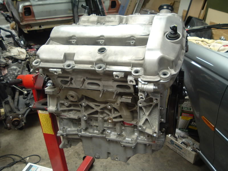
It's been a while since my last update, but I'm about half way through the rebuild/reinstall process. As of tonight, the rebuilt motor is back on the subframe, bolted to the transmission. I still need to mount all of the accessories and wiring harness to the engine, but the motor itself is back with the rest of the drivetrain.
The following are pics from the process.. starting with the barely block on an engine stand, to the complete motor.
I'll comment a little on each of them as I go.. So, here we go! ..
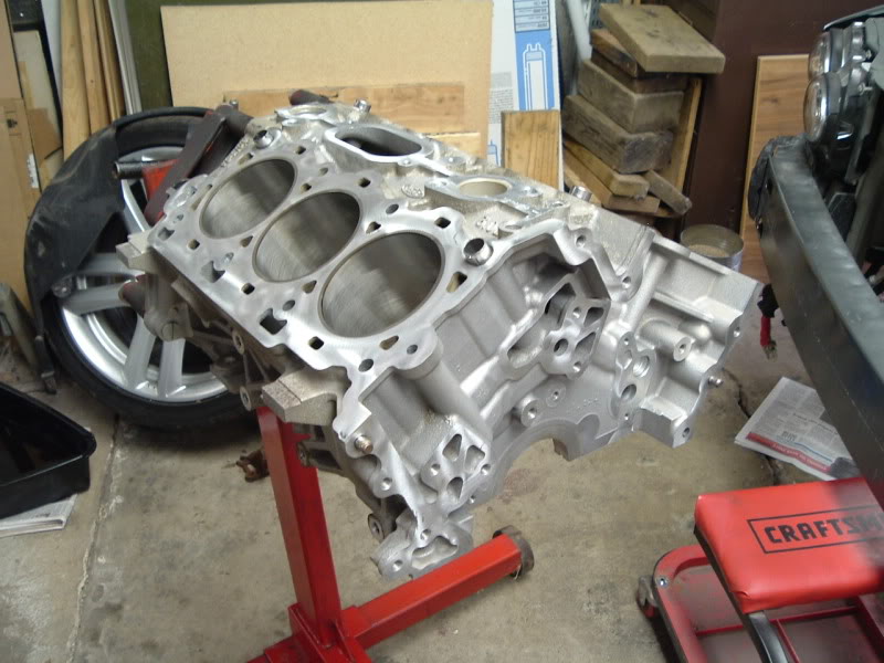
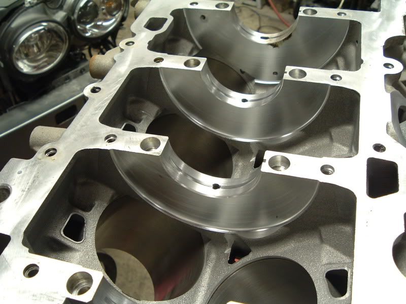
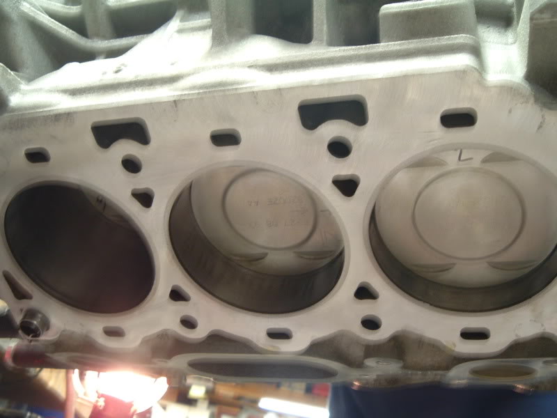
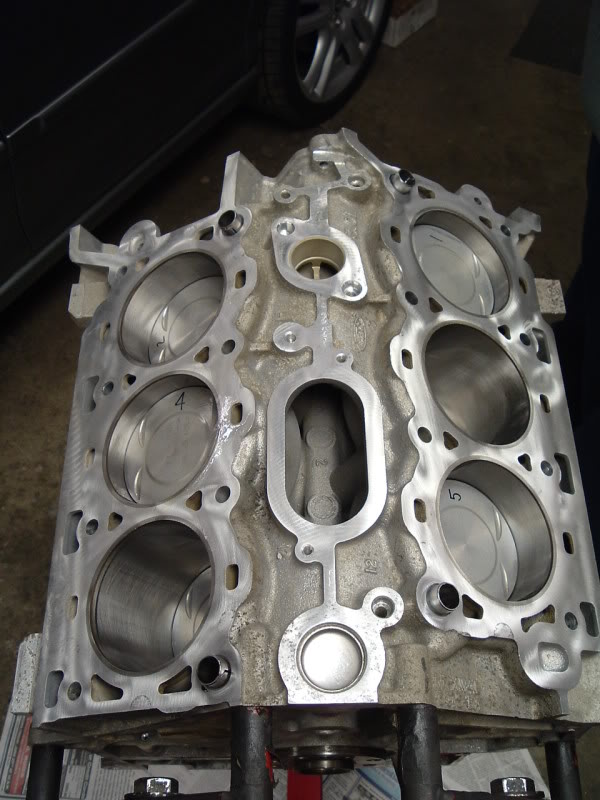
The bare block back from the machine shop. They deglazed/rehoned the cylinders and hot tanked it.
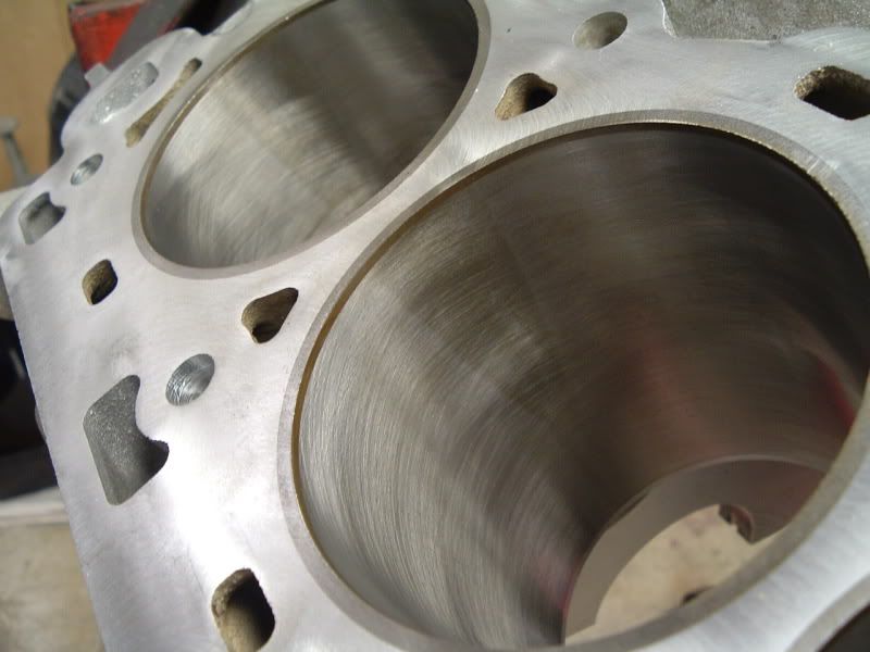
Notice the steel sleeves pressed into the aluminum block.
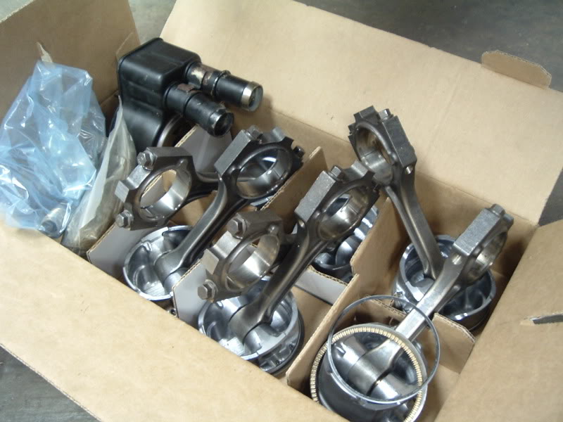
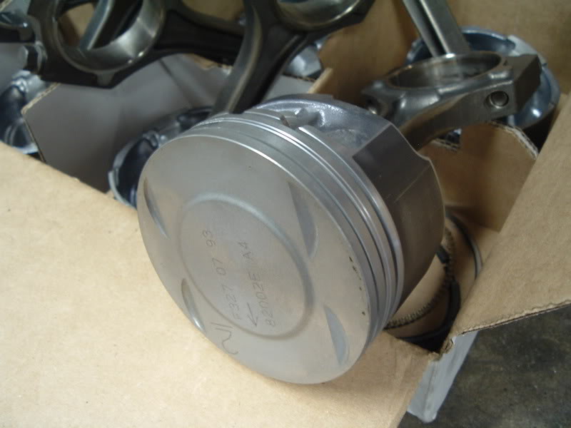
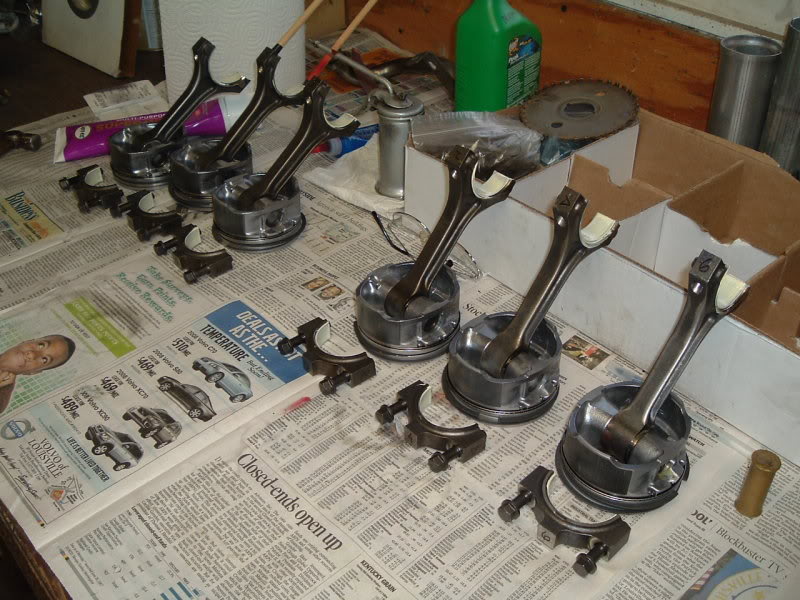
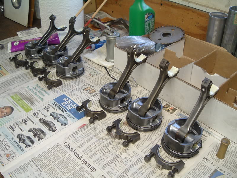
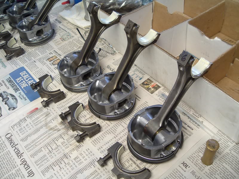
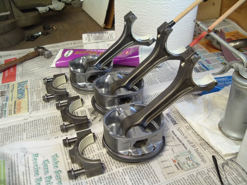
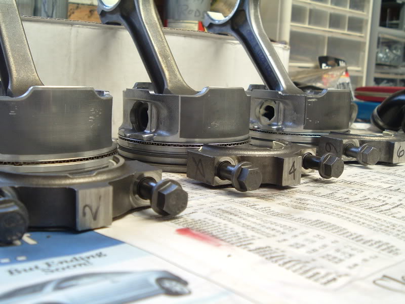
A box with various things.. Old main/head bolts (not to be reused), the oil filter housing, old bearings, two rods that had to be replaced, and the six rod/piston assemblies.
MMmmmmm..... clean
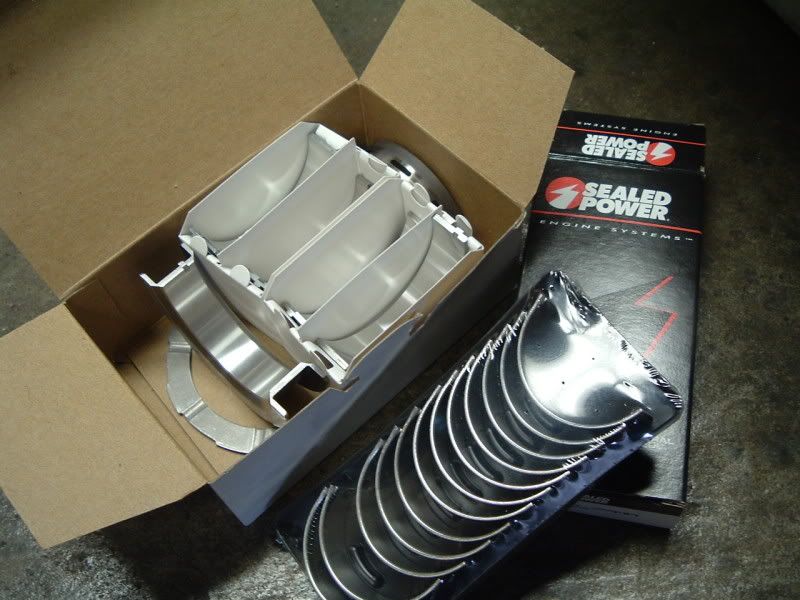
New bearings!
Over $500 worth of (necessary) bolts.
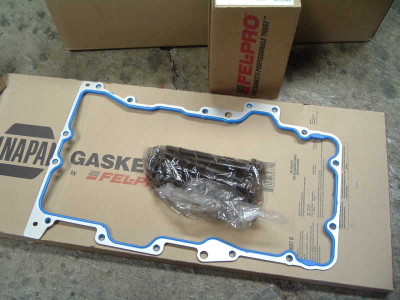
The new oil pan gasket.. an item which I know many of you will end up seeing. :/
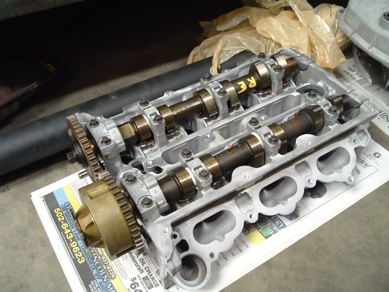
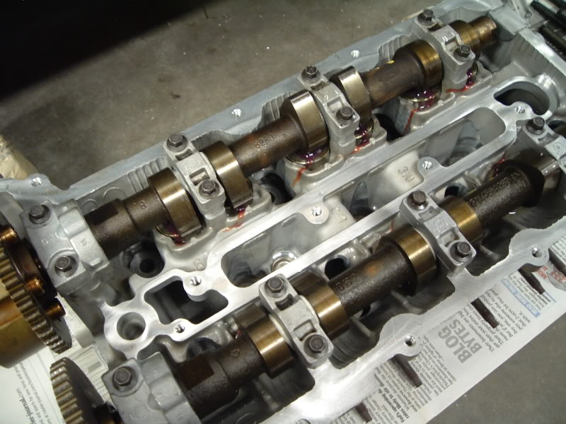
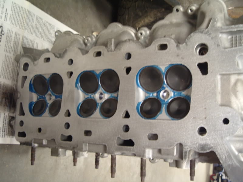
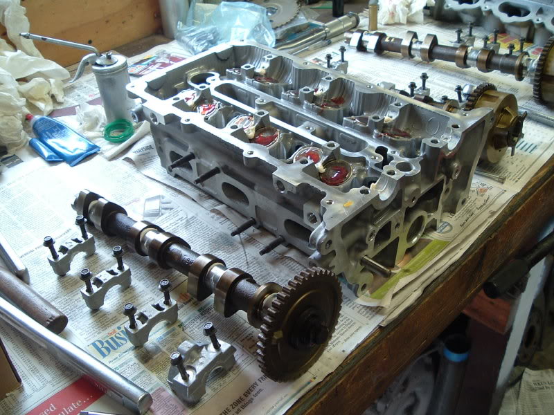
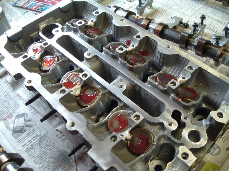
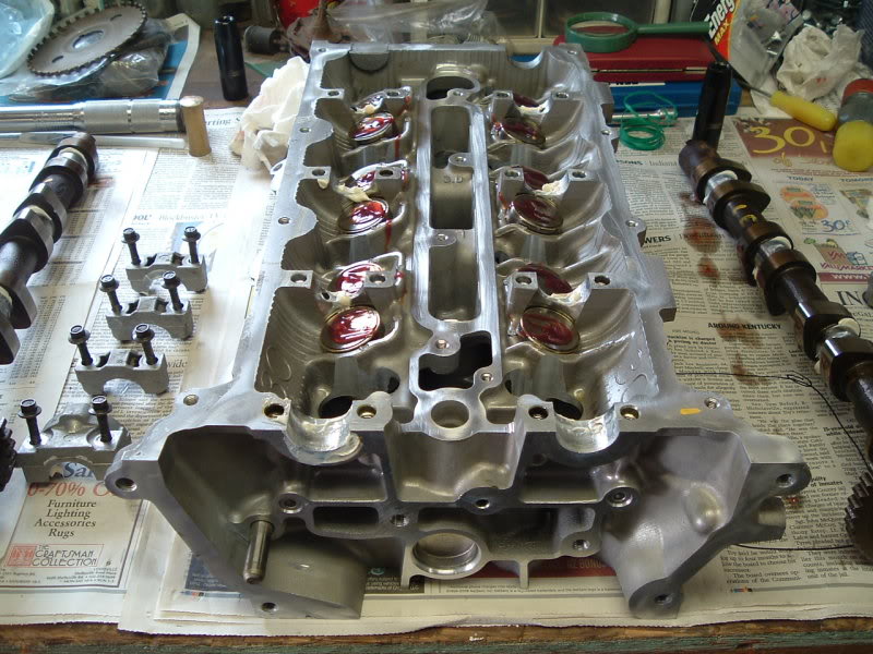
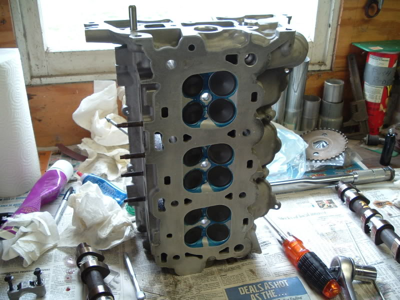
Rebuilt head, with all new valves seals, and all valves adjusted.
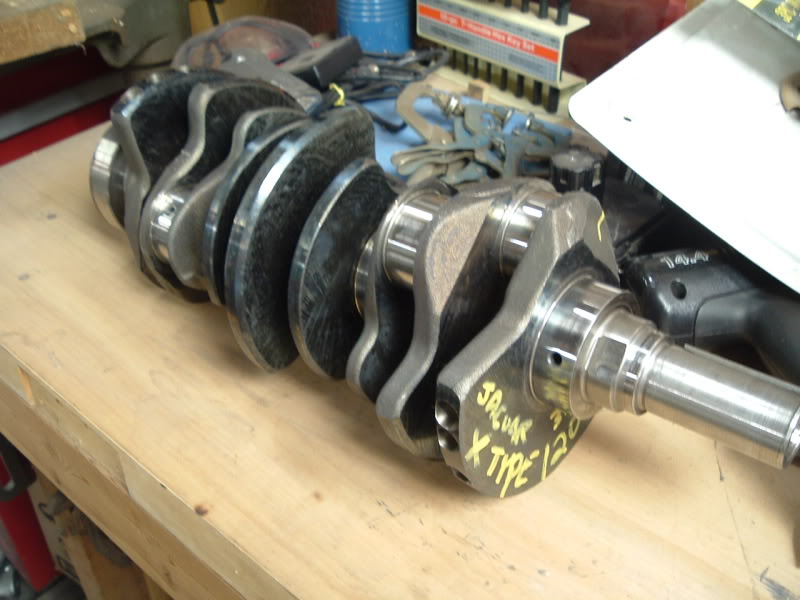
The crank.. which has been straightened, had the mains bored .010 and the rods bored .020.
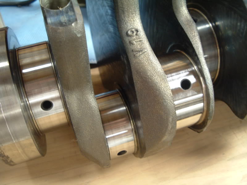
Much better now than when it came out.
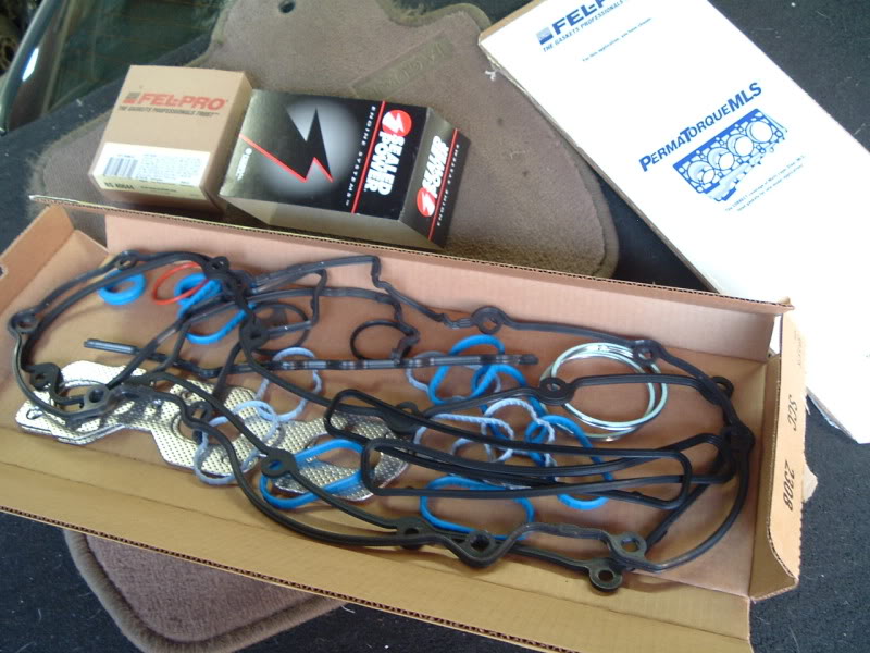
The Fel-Pro gasket set, which turned out to be junk. It was missing roughly 10 various coolant related o-rings, and one of the valve cover gaskets was wrong.
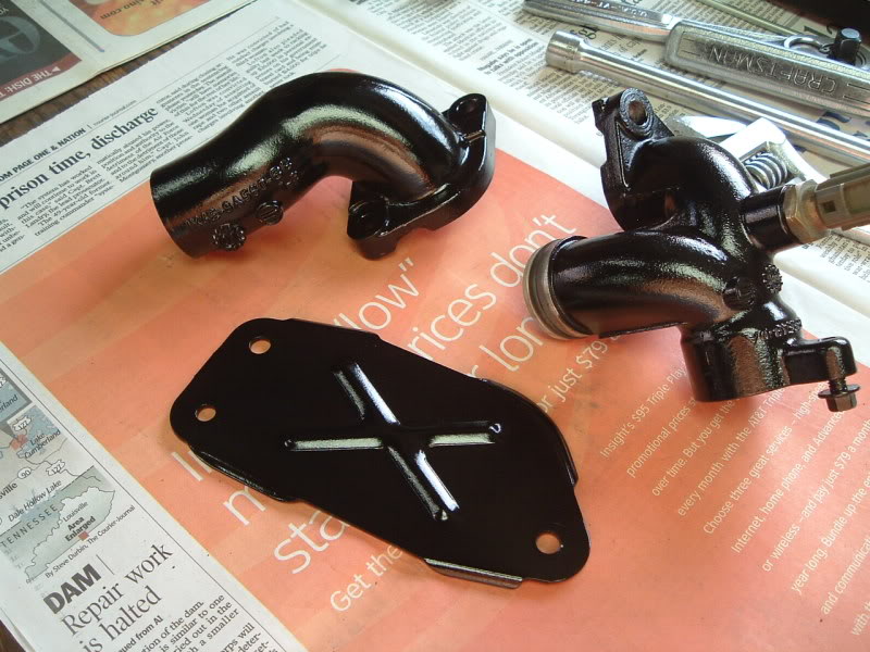
Just a quick shot of a couple coolant fittings and the valley block plate that I wire wheeled and painted.
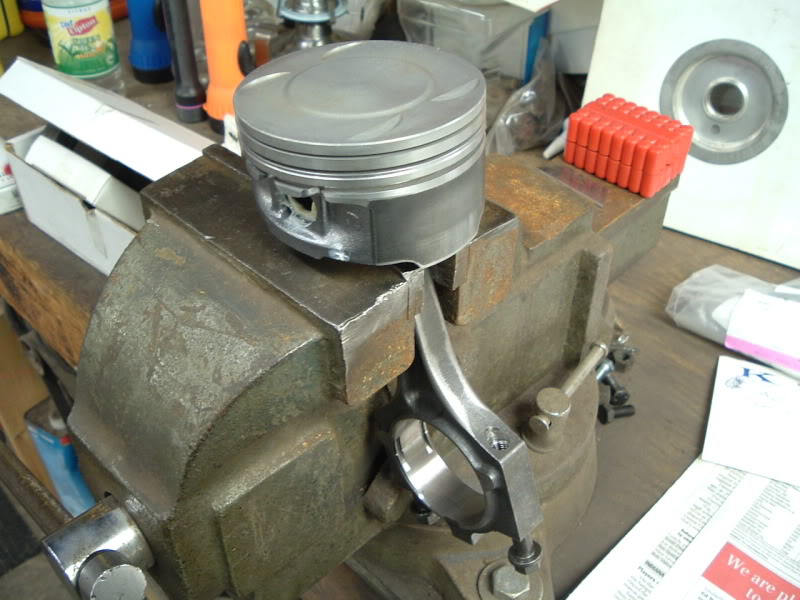
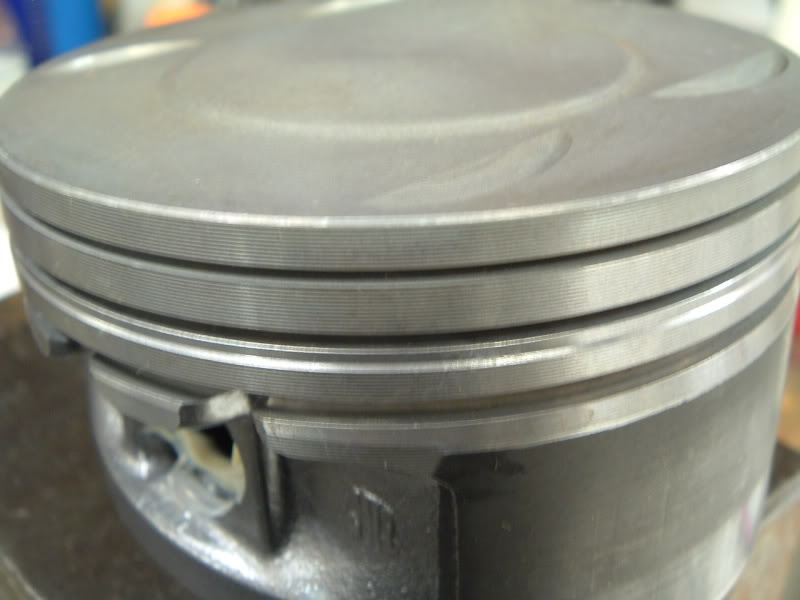
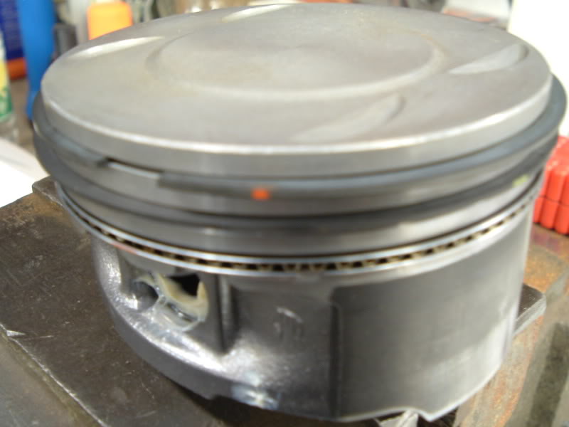
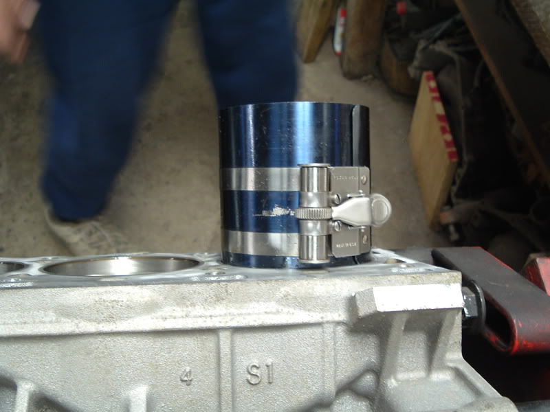
Installation of the piston rings. As mentioned in the other thread, I had to use oem Jag ones from the dealer ($355 for the set), versus the $150 SealedPower ones that were supposed to be a match, but definitely weren't.
The following are pics from the process.. starting with the barely block on an engine stand, to the complete motor.
I'll comment a little on each of them as I go.. So, here we go! ..
The bare block back from the machine shop. They deglazed/rehoned the cylinders and hot tanked it.
Notice the steel sleeves pressed into the aluminum block.
A box with various things.. Old main/head bolts (not to be reused), the oil filter housing, old bearings, two rods that had to be replaced, and the six rod/piston assemblies.
MMmmmmm..... clean
New bearings!
Over $500 worth of (necessary) bolts.
The new oil pan gasket.. an item which I know many of you will end up seeing. :/
Rebuilt head, with all new valves seals, and all valves adjusted.
The crank.. which has been straightened, had the mains bored .010 and the rods bored .020.
Much better now than when it came out.
The Fel-Pro gasket set, which turned out to be junk. It was missing roughly 10 various coolant related o-rings, and one of the valve cover gaskets was wrong.
Just a quick shot of a couple coolant fittings and the valley block plate that I wire wheeled and painted.
Installation of the piston rings. As mentioned in the other thread, I had to use oem Jag ones from the dealer ($355 for the set), versus the $150 SealedPower ones that were supposed to be a match, but definitely weren't.
Trending Topics
#8
03-27-2009, 11:09 PM
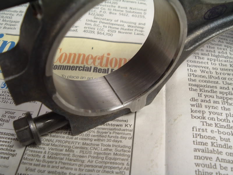
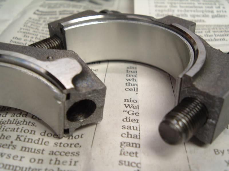
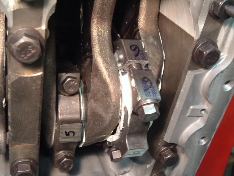
The connecting rods are interesting.. This is one of the two new ones I had to buy. When you unscrew the bolts, you have to crack the end cap off of the rod with a hammer. This rough break ensures each end cap is unique to the rod it came off of, and fits back very securely.
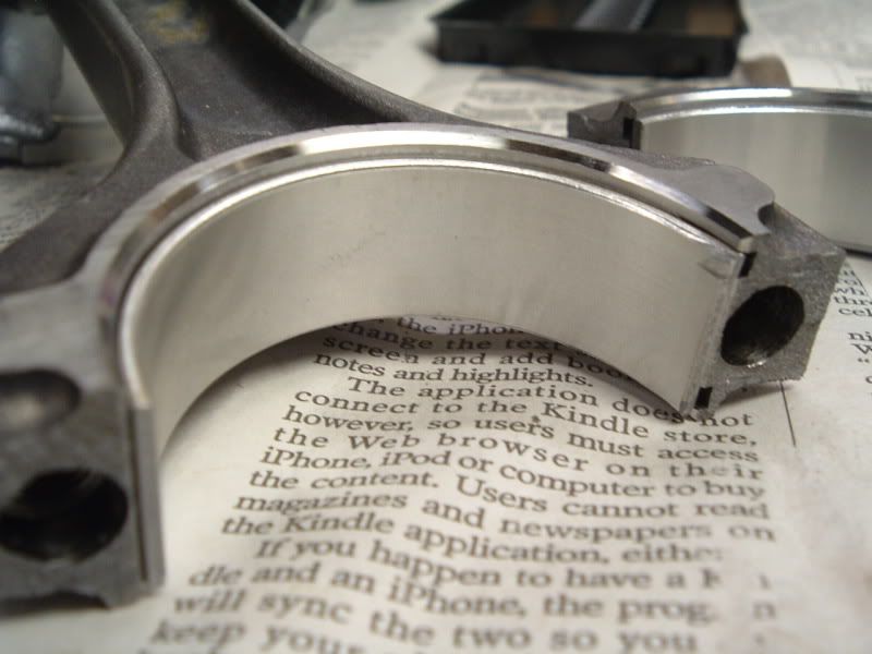
New bearing fitted
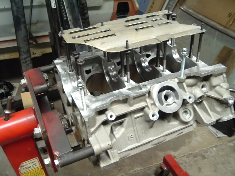
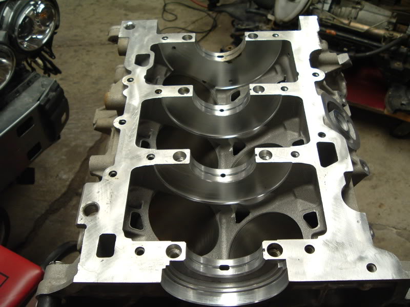
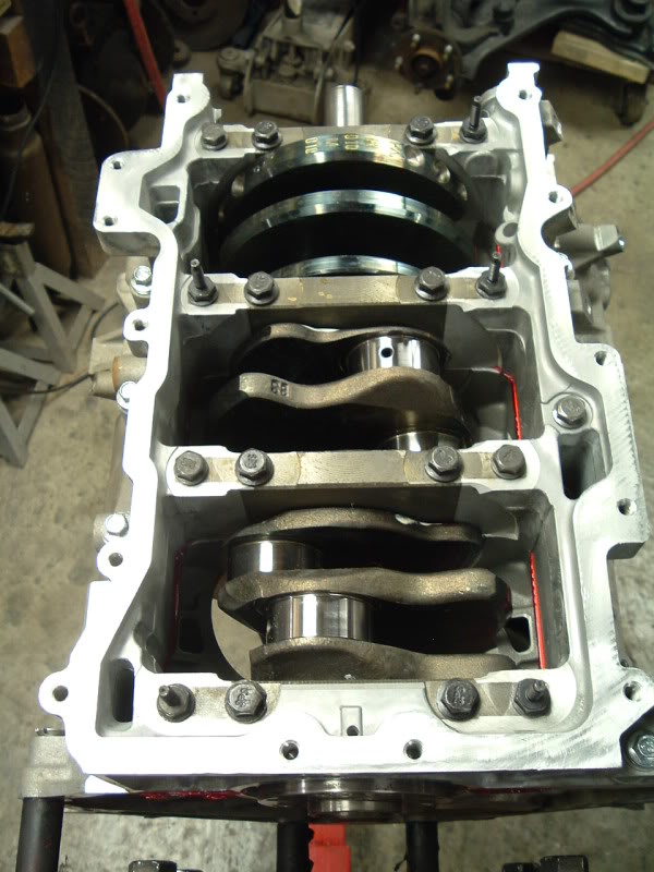
The lower block/main bolts mocked up with the windage tray.
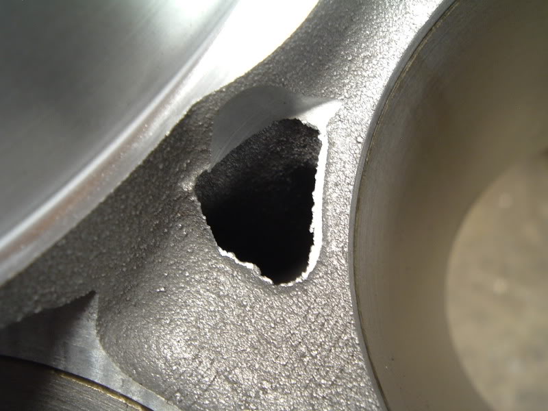
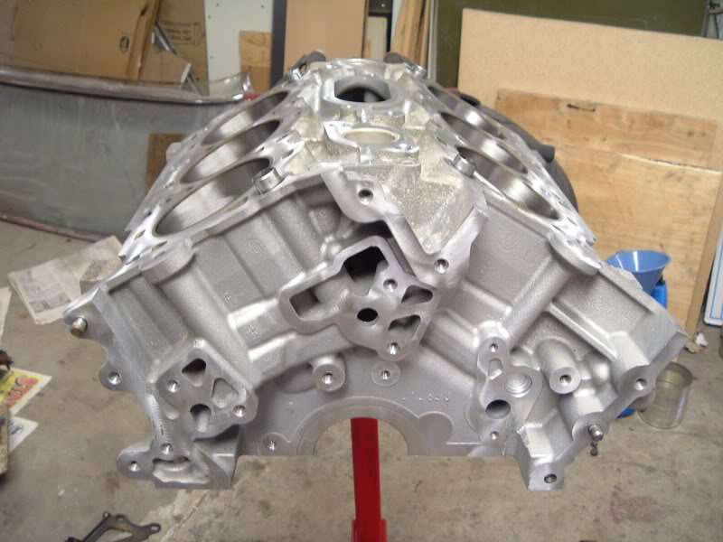
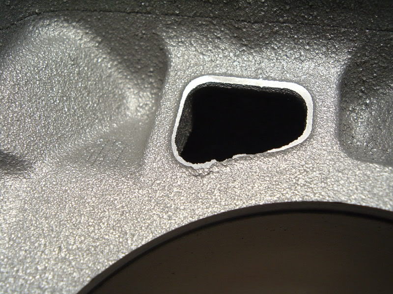
These three pics are examples of rough and unfinished coolant passages in the block. There are places like this all through the motors.. that just look.. crappy. Especially where the lower block meets the upper block. It just looks like a poor casting job.
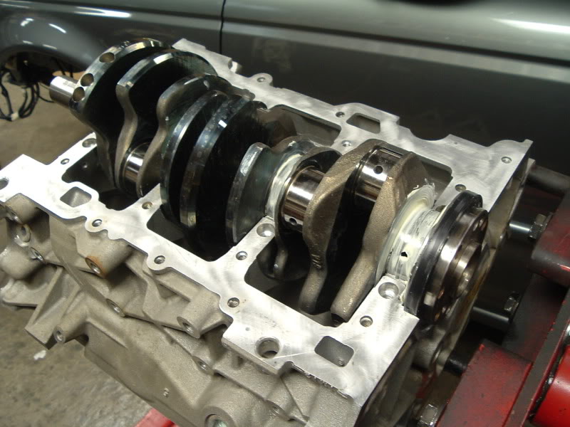
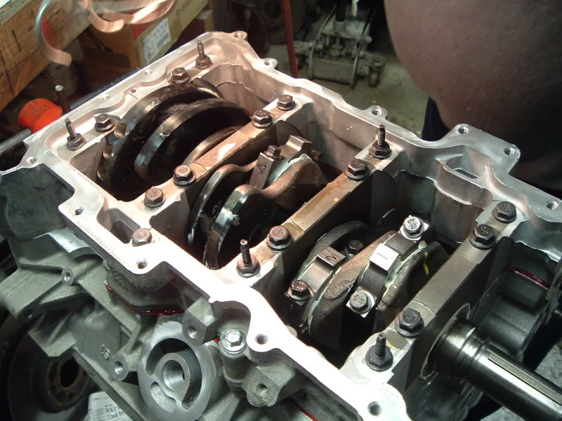
Main bearings/crank in place, and heavily lubed.
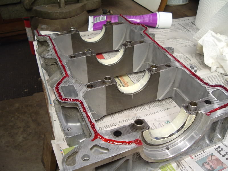
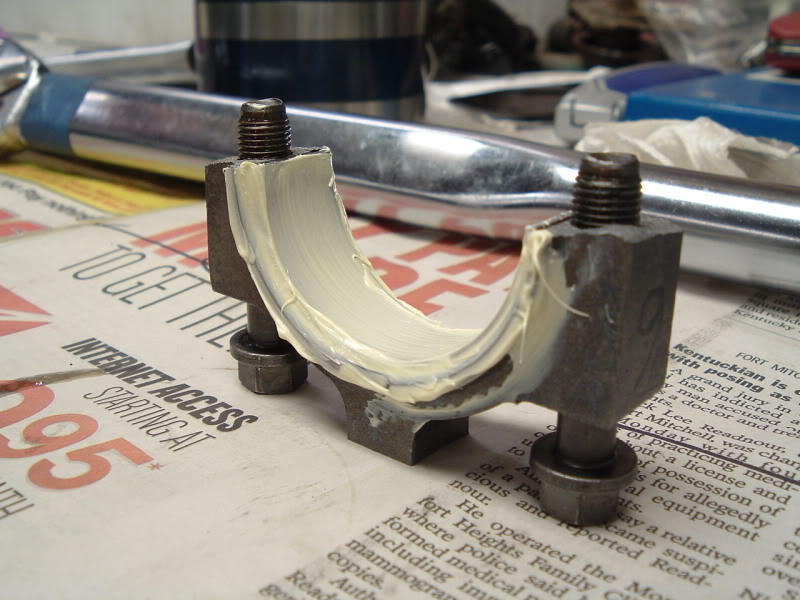
Anaerobic gasket maker is to be used instead of standard silicone. This stuff was not cheap, and not every parts store has it. It's the best stuff to use on aluminum, especially between two machined surfaces.
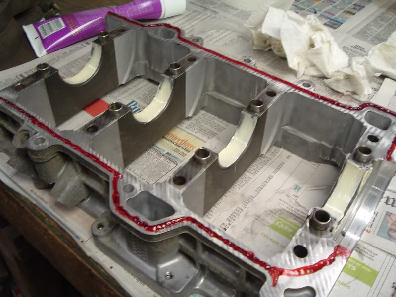
It doesn't take much, either. This was about twice as much as I should have used.
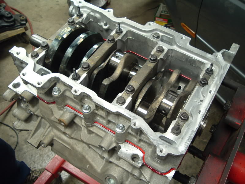
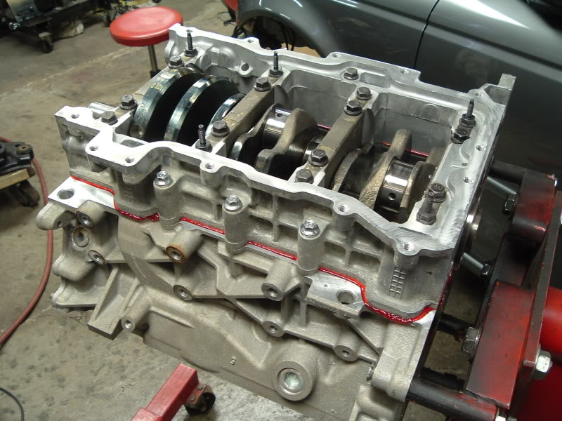
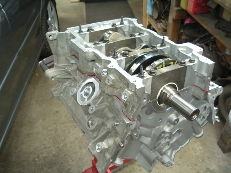
Lower block installed and torqued.
#9
03-27-2009, 11:17 PM
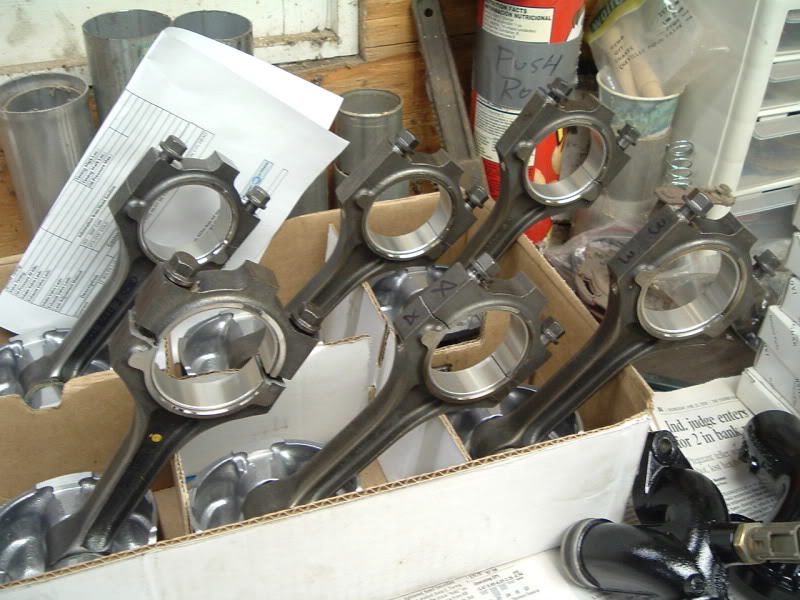
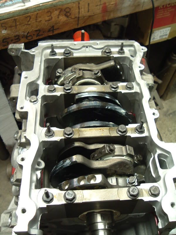
Rings, bearings, and new bolts installed... Ready for installation. The key to a smooth rebuild is to stay organized and plan ahead.
Lots of assembly lube is a must. White lithium grease in a big toothpaste like tube works great.
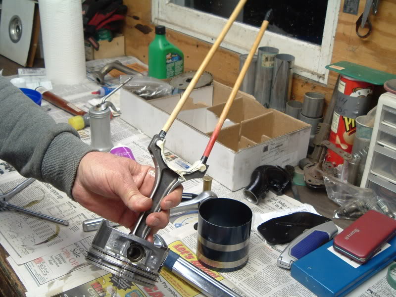
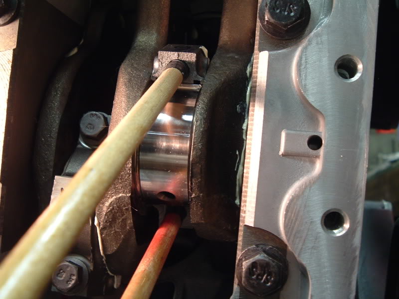
Guide rods stuck into the holes in the end of the rod help guide it onto the crank.
Piston fed into the block from the top, and coming down to meet crank.
Piston rings compressed, piston drove into block.
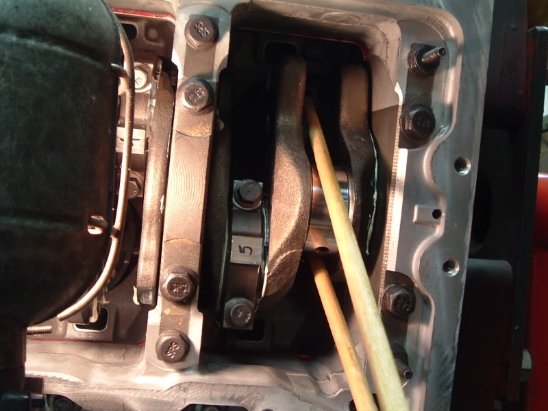
Almost there...
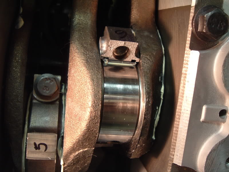
Firmly seated onto crank.
End cap in place
Torque, and repeat five more times.
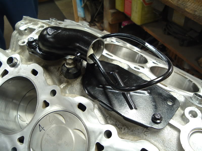
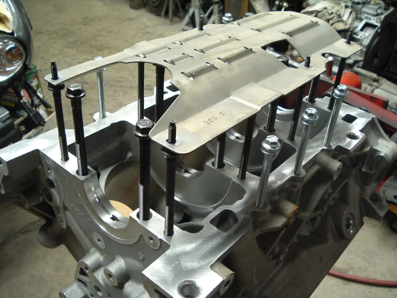
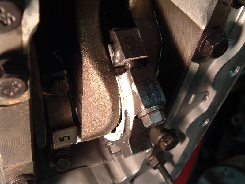
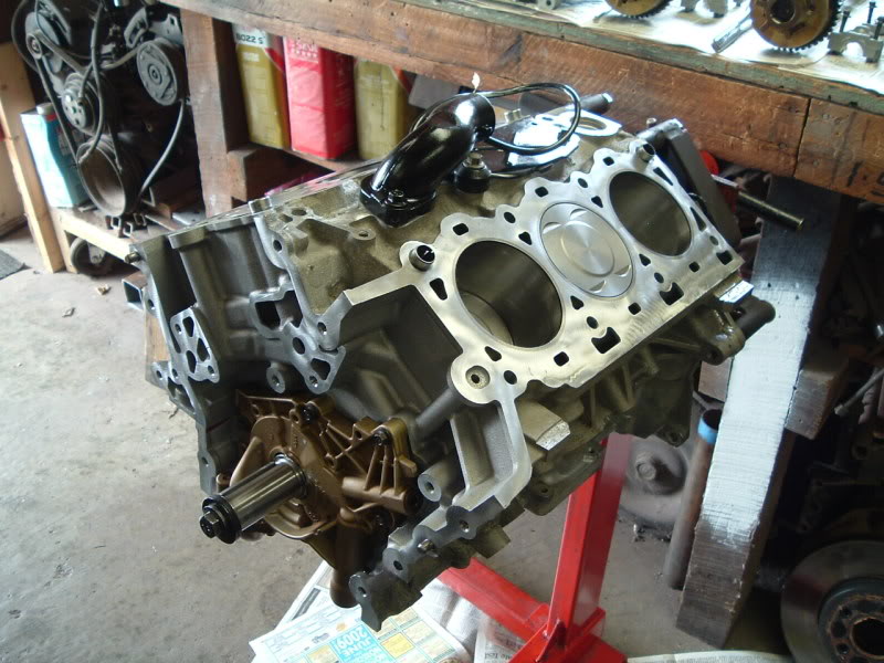
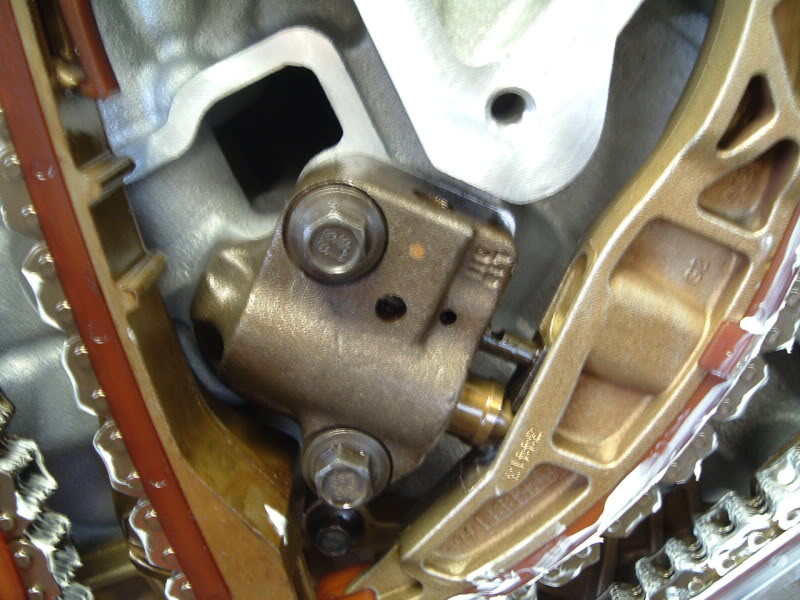
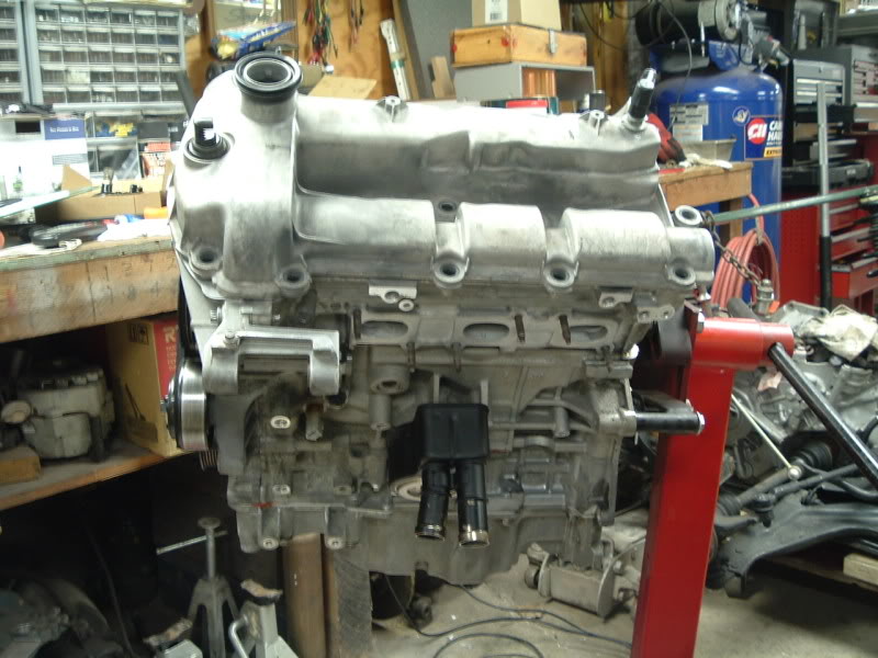
Coolant fitting, knock sensor, and blocking plate in place.
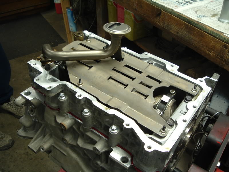
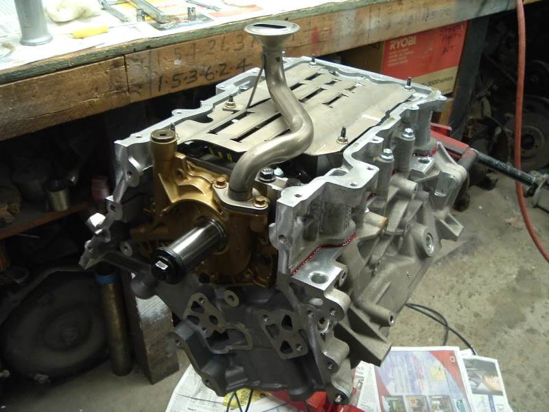
Oil pump, pickup, and windage tray installed.
Last edited by 310jag; 03-27-2009 at 11:36 PM.
#10
03-27-2009, 11:23 PM
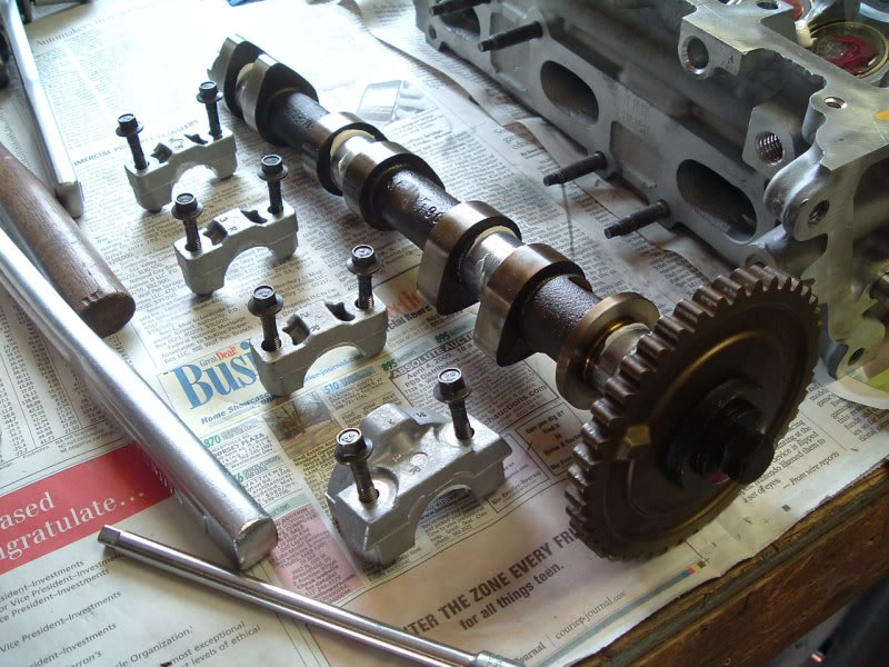
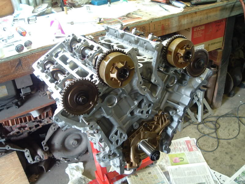
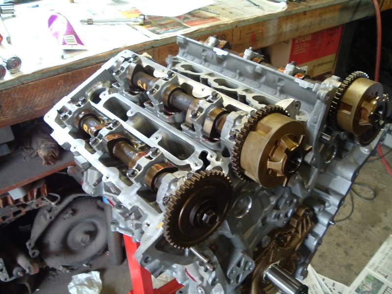
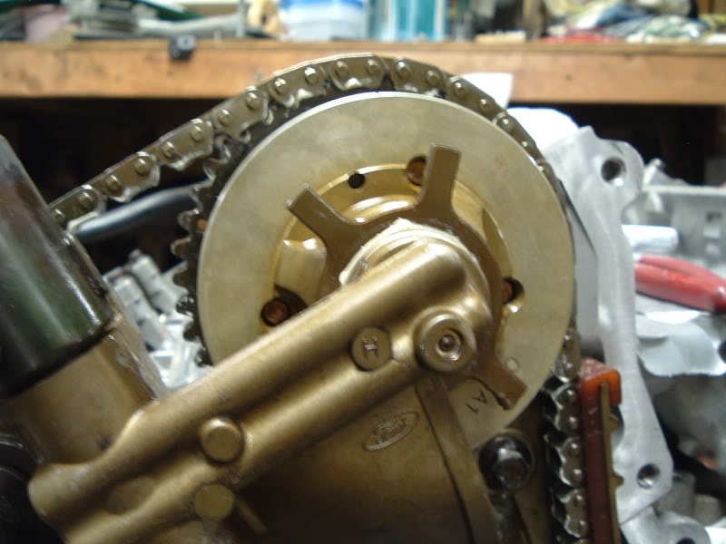
On to the heads!
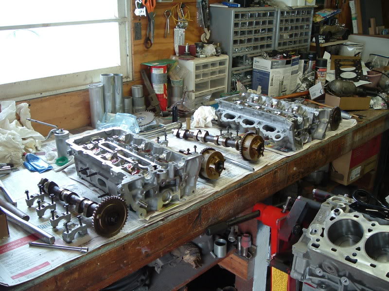
Exploded view
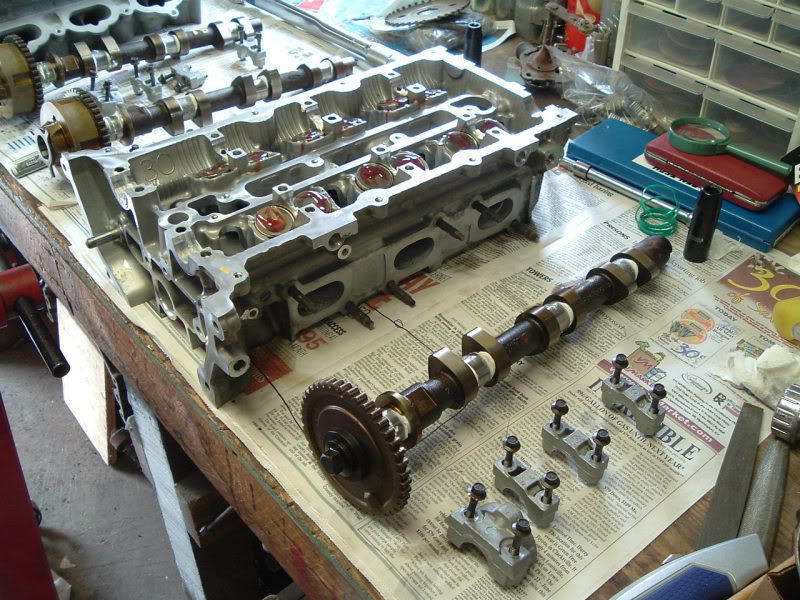
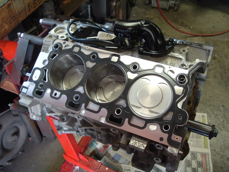
Head gaskets in place
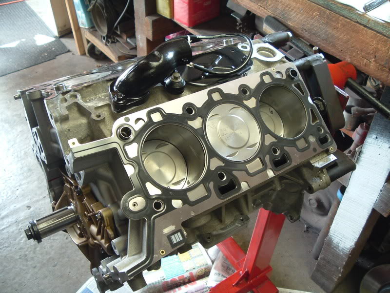
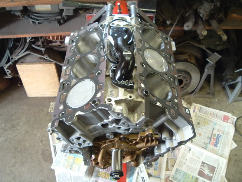
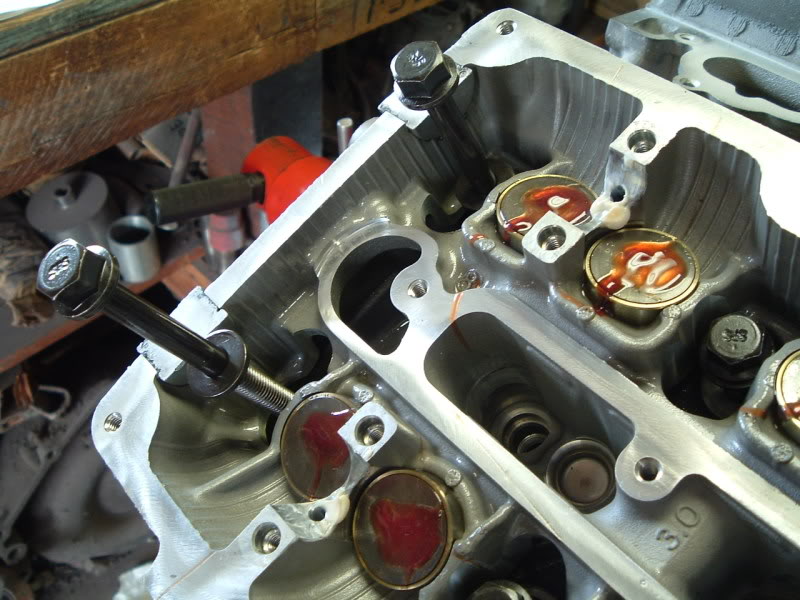
Installed with new head bolts
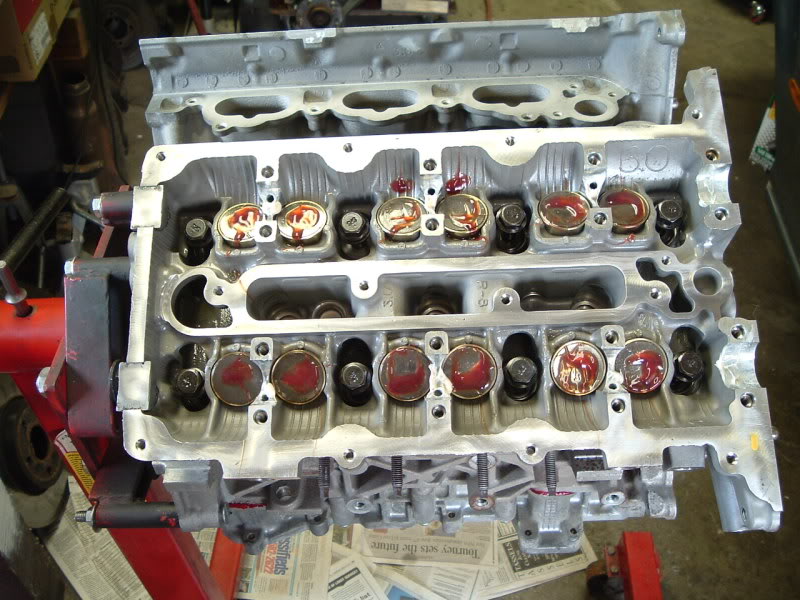
Both sides in place
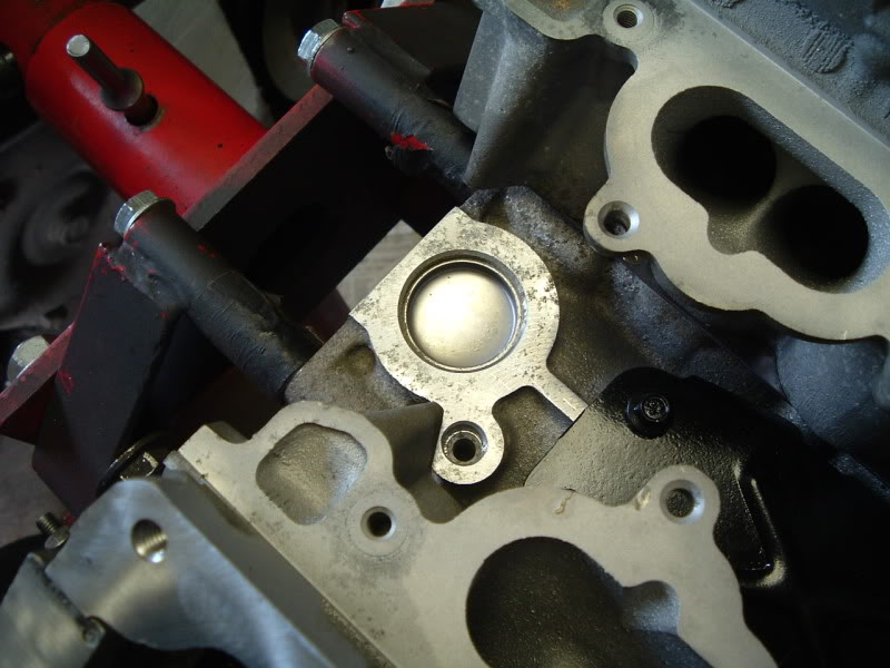
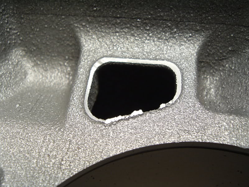
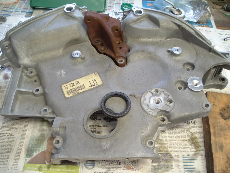
Nothing really special about this, but I thought I would point it out. This is a hole in the top of the block at the rear that has been filled with a freezeplug, and has a threaded hole next to it. This is where a standard distributor was installed for other variations of the Duratec, and blocked off for this application.
Exploded view
Head gaskets in place
Installed with new head bolts
Both sides in place
Nothing really special about this, but I thought I would point it out. This is a hole in the top of the block at the rear that has been filled with a freezeplug, and has a threaded hole next to it. This is where a standard distributor was installed for other variations of the Duratec, and blocked off for this application.
#11
03-27-2009, 11:30 PM
The following users liked this post:
Thang Nguyen (05-26-2016)
#13
03-28-2009, 08:46 AM
The following users liked this post:
Thang Nguyen (05-26-2016)
#15
04-02-2009, 01:57 PM

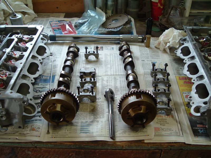
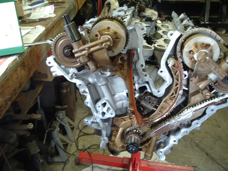
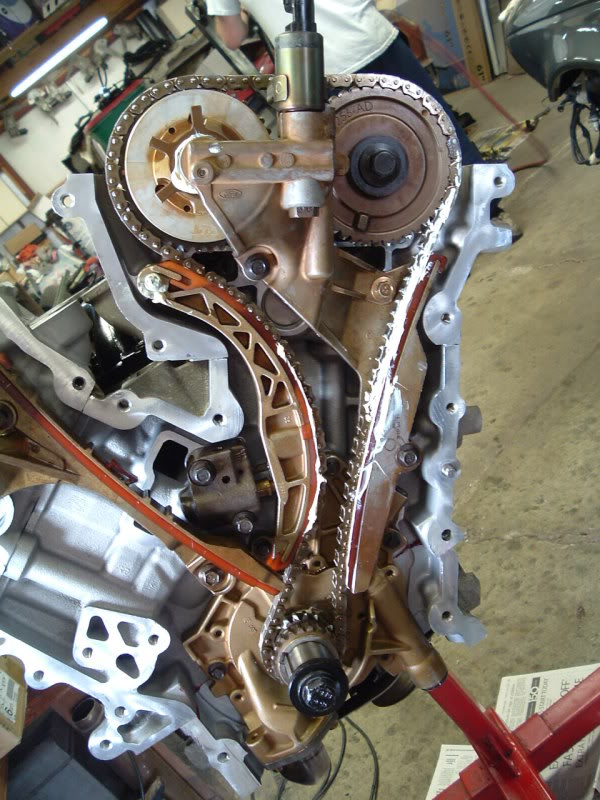
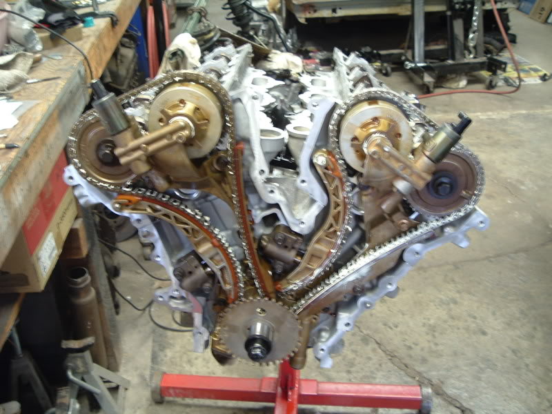
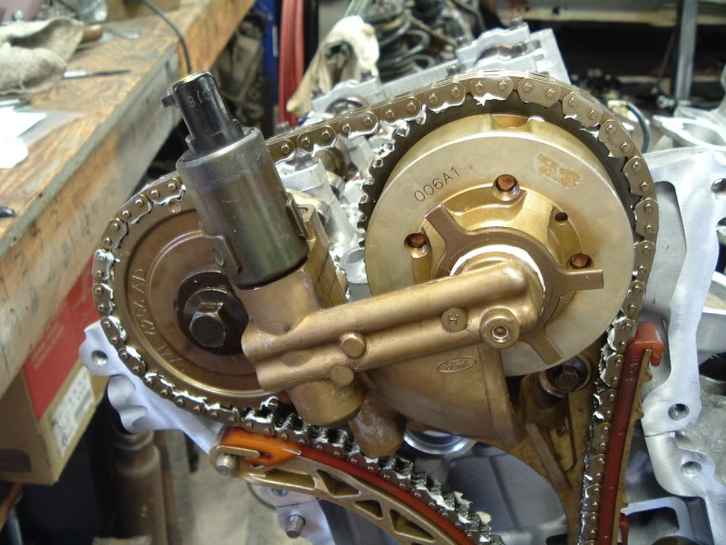
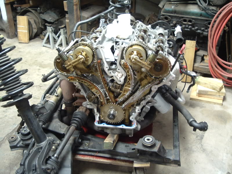
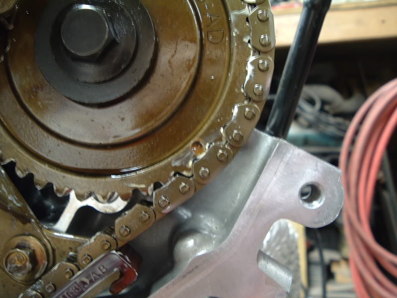
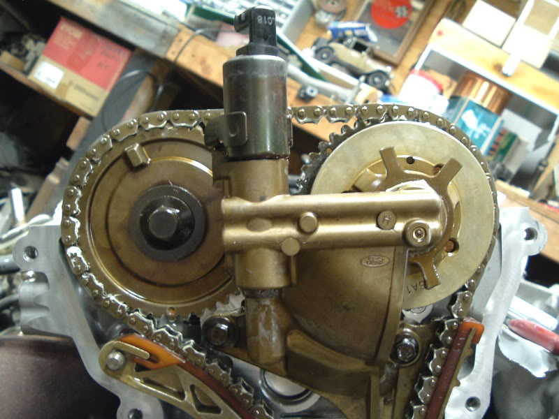
My timing marks are 180 from JTIS. My key was at 3 O'clock not 9. I tried but could not ever get the "First Cylinder" on the crank to be at TDC when marks align at 9. I tried and tried. So I figured that I should document this for when I rebuild. I may be wrong and be at the exhaust stroke and not compression, however it really doesn't matter as long as the chains go back the same way.
I ended up with #2, the Second Cylinder on the Crank, and #5, the Fifth Cylinder on the Crank at TDC. I was MOSTLY intrested in getting my CAM marks to line up with the JTIS pictures. I could ONLY acheive this under these positions. You will notice the "link" is just after the 3 O'clock mark. The same is true with the CAM marks, yellow dot. I counted 33 links CW to the 11 O'clock cam mark and 15 links between cams and then 22 from the 5 O'clock cam. (maybe 4 O'clock)

Chain link mark just AFTER the 3 O'clock key position. Piston #2 of Crank is at TDC and Piston #5 on the crank is TDC

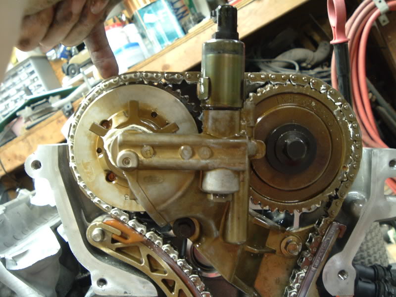
PLEASE NOTICE the background for camera angles. This angle is square with floor.

I tried to make it look like JTIS so I squared camera with the VVT cross brace.

Mark on Intake CAM about 5 O'clock (maybe closer to 4 O'clock). As You can see it has just come away from the chain


This is the RIGHT SIDE CAM set-up

SAME as LEFT side CAM set-up
I now have ALL my parts back from the Shop. I was told after a month that they just do not feel comfortable re-building this motor. The problem was that they are European specialist, LandRover, BMW but they have not done ANY of these Jaguar engines. They were not interested enough to download the JTIS and "Assemble" the motor. Just as well, I feel pretty confident I can do this. I have been over it in the manual many times. I even created an assembly document that I created for the shop. I am involved in another project for the next couple weeks but the weekend of the 10th I will resume with project.
Those of you who think you can do this, as I did, need to re-think it. The COST really begins to add-up. I had to pay $30 for a bolt and you need 5 of them. I recently paid $480 for all the "lower-end" bolts. These hold the Mains on, the "bed" ,as they call it, to the other half of the block and the ones that are used to hold the Oil Pan baffle. Add that to the $120 in head bolts. Then you get into decisions like "do I replace the oil pump or the water pump while it's apart. Then you have the entire gasket issue/cost. There is also about $680 in Rings, main bearings and rod bearings. Then there are about $200 in o-rings. It seems like the $$$$ continue to flow out of your pocket. I am doing this because I consider it relaxing and I plan to keep the vehicle for many more years.
As an alternative there is a company called EverDrive http://www.everdrive.com/ that will sell you low mileage motors with 3 year unlimited mileage for about $3500, shipping not included.
Last edited by jfenley; 04-08-2009 at 08:54 AM.
The following users liked this post:
Thang Nguyen (05-26-2016)
#17
04-04-2009, 11:45 PM
I've got a lot to say about the timing, but for chronological reasons, I'll go ahead and get these ~20 pics out of the way.
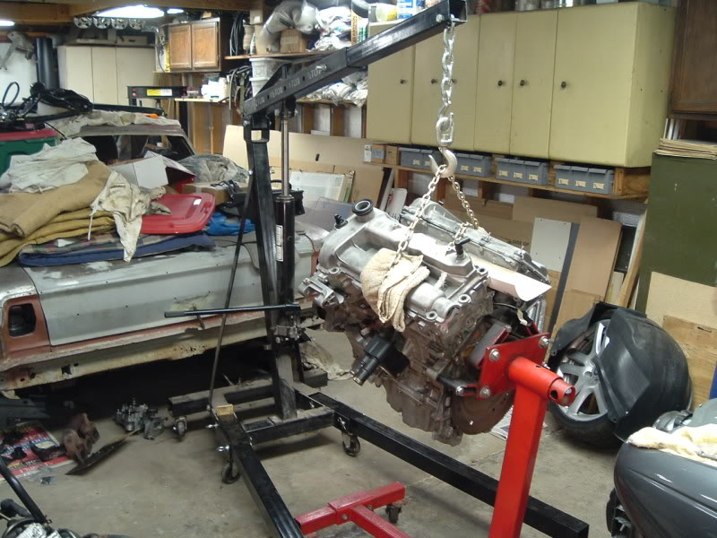
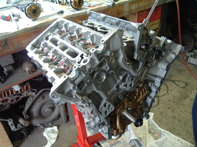
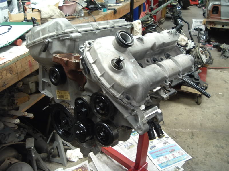
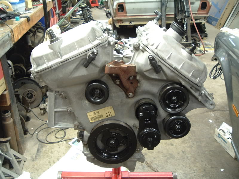
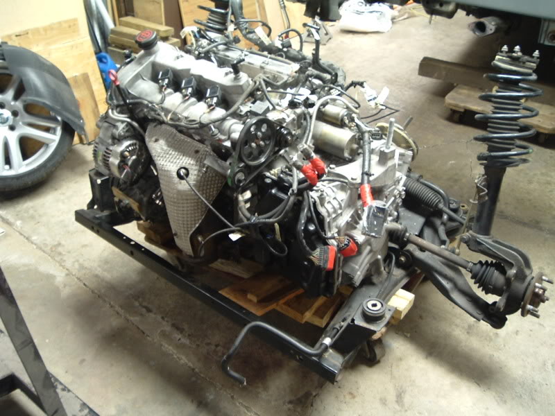
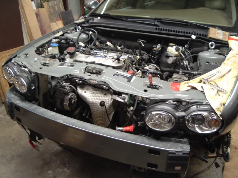
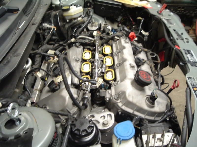
Engine on the hoist, ready to be removed from the stand and reinstalled on the subframe.
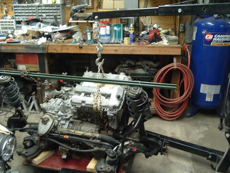
Installed, and mated to bellhousing.
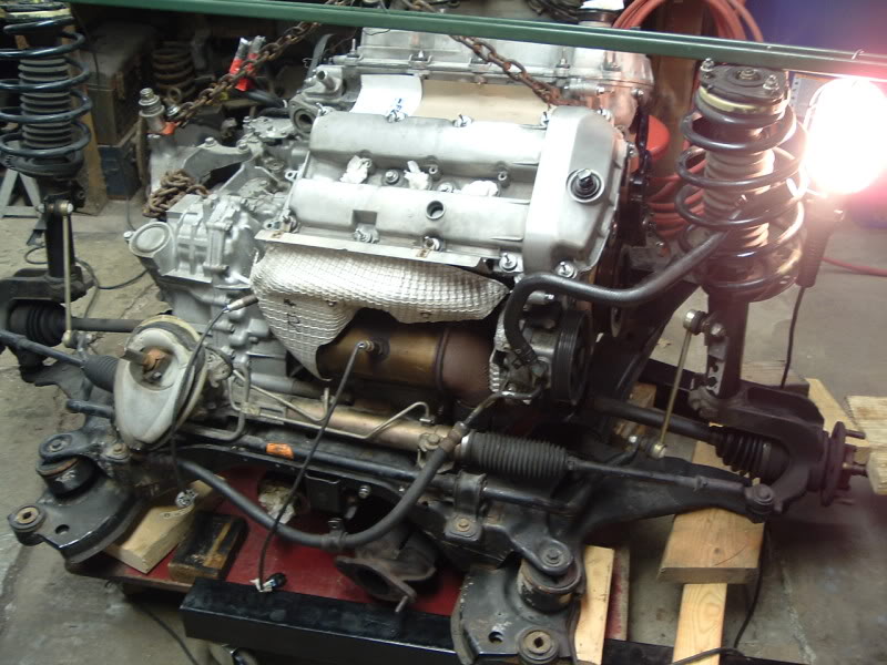
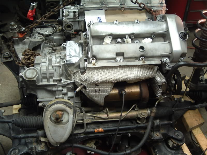
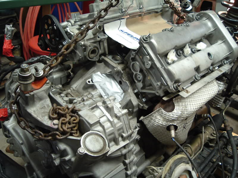
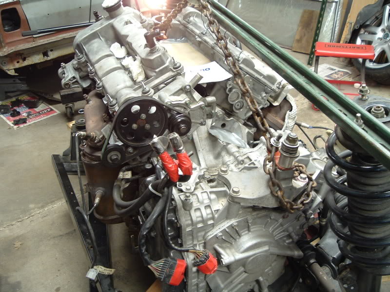
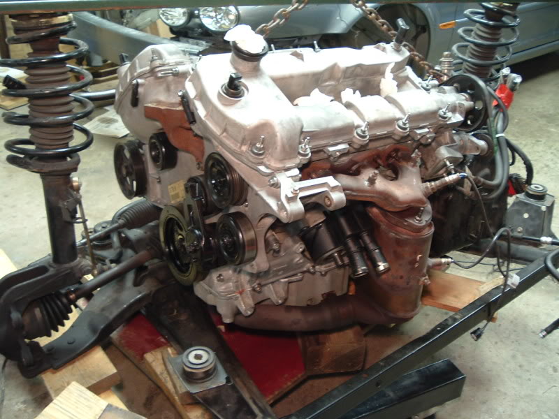
Ready to go back in.
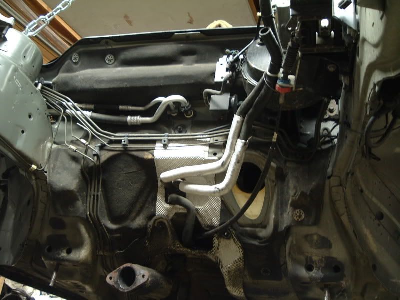
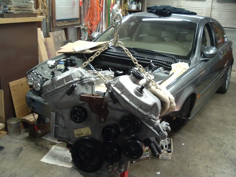
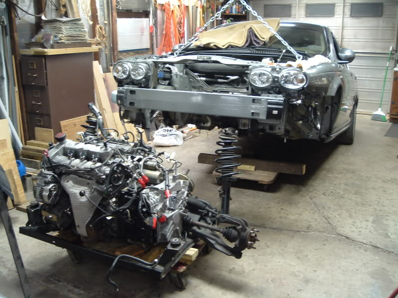
A view that very, very few people will ever see of their X. This is looking up from the ground at the firewall with an empty engine bay.
Rear wheels still on the ground, front end up in the air.
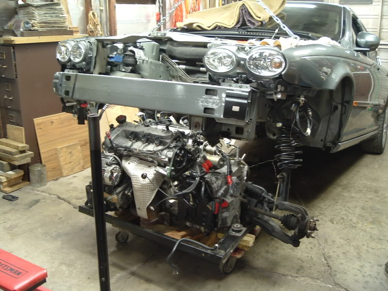
Package going under.
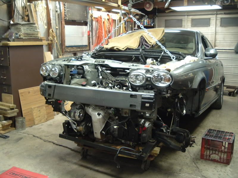
Aligned.
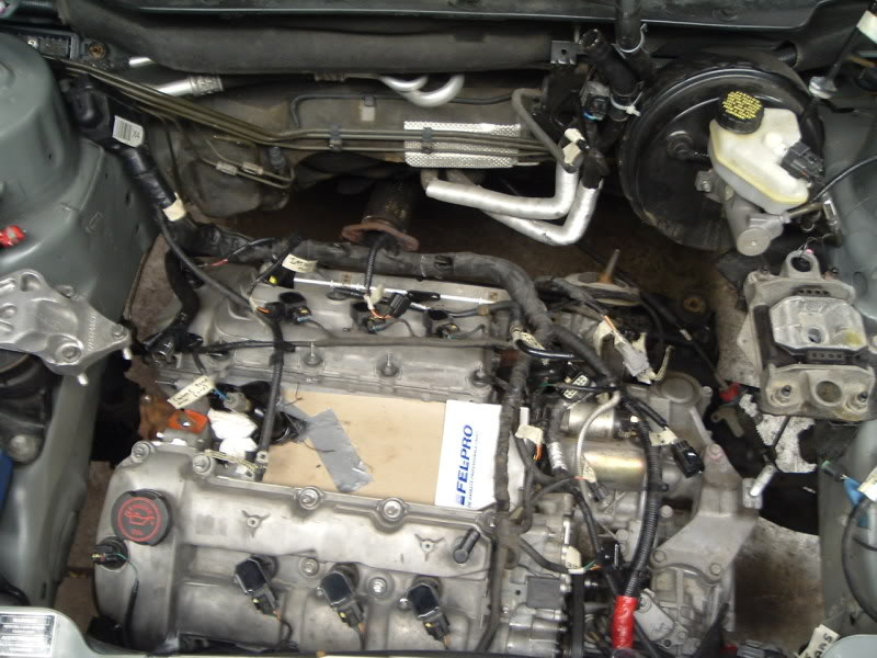
Raising the package into the engine bay.
Engine on the hoist, ready to be removed from the stand and reinstalled on the subframe.
Installed, and mated to bellhousing.
Ready to go back in.
A view that very, very few people will ever see of their X. This is looking up from the ground at the firewall with an empty engine bay.
Rear wheels still on the ground, front end up in the air.
Package going under.
Aligned.
Raising the package into the engine bay.
#18
04-05-2009, 12:09 AM
Now, here's where things go to crap. After those last couple of pictures, I charged on, and assembled everything else that needed to be done in order to start the car. After MONTHS of anticipation, thousands of dollars, and endless frustration, I turn the key.
It cranks.
And cranks.
And cranks.
It finally fires, runs for 5-6 seconds, and stalls out with a buck, and wouldn't restart. It cranked very roughly, burped out of the intake, and just didn't sound good. The timing was off. Apparently I had too much faith in the accuracy of the JTIS timing instructions, and the advice given on the 3 liter motor blog. They're wrong. WRONG. After all of this work, I'm screwed up by someone's else bs instructions. Whoever wrote the JTIS section on timing for the X-type should HANG.
As of now it's throwing tons of codes, Cruise Not Available, Gearbox Fault, DSC system fault, CEL, and both red and yellow lights.
The gearbox and DSC messages kind of throw me off.. Even with motor problems, I didn't expect those. I know there's really nothing wrong with the tranny as it was just replaced a year ago, and hasn't acted up at all.
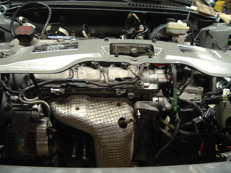
Long story short, here it is tonight. After removing the engine for the SECOND time, I'm going to tackle the timing tomorrow.
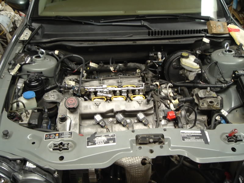
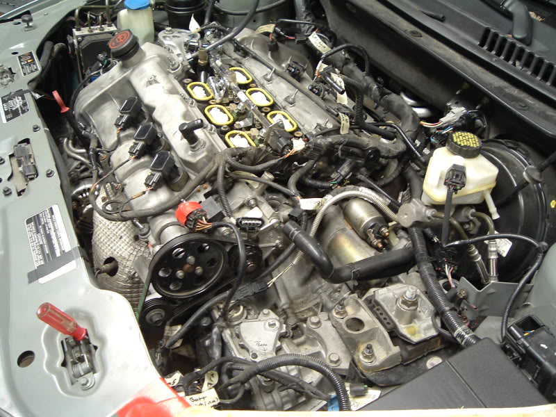
I pulled the valves covers, accessories, pullies, and front cover to get to what I needed to, without putting it back on the stand or removing the oil pan (just the front two pan bolts).
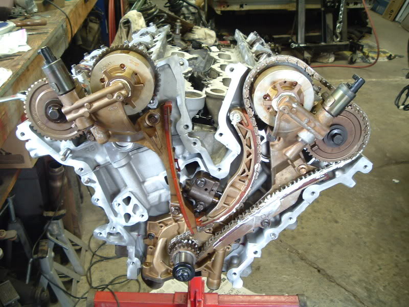
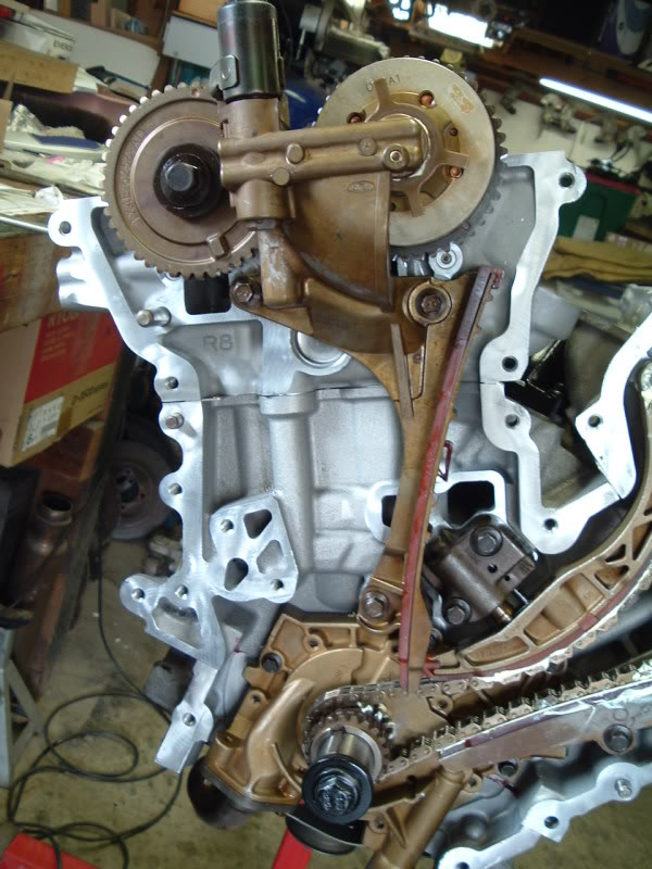
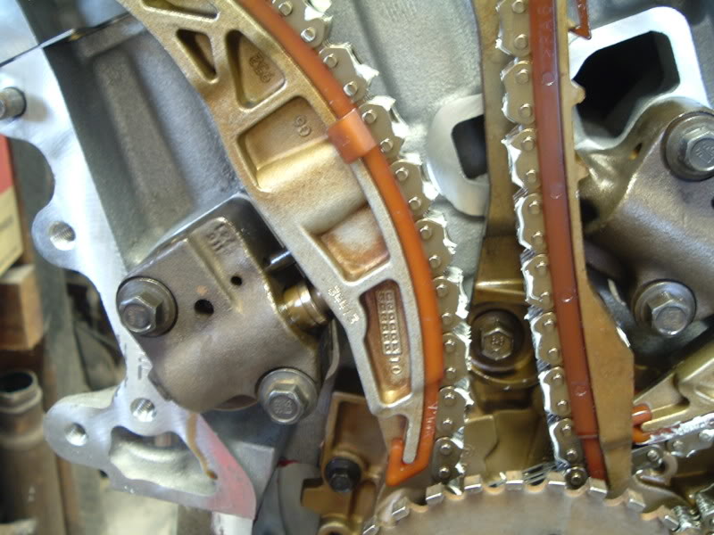
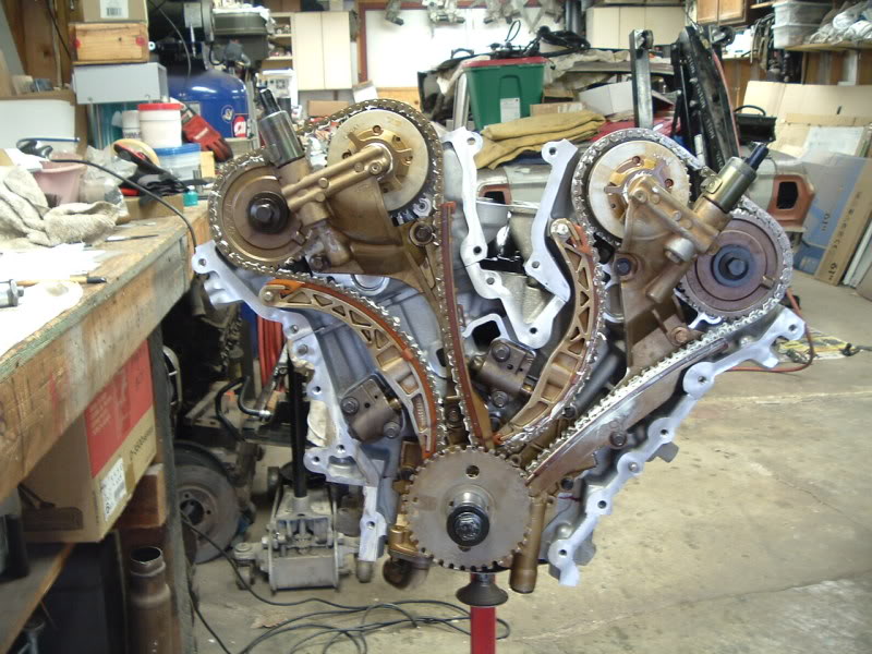
As it is now.. I know the rear bank is 180 out, so here's the front bank which I think may be alright (but I'm doubtful....James?)
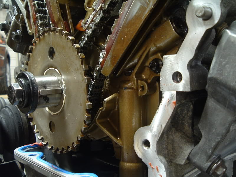
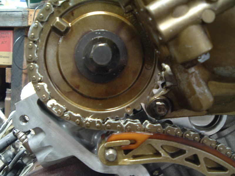
Crank keyway at 3 on the dot.
Front bank exhaust cam timing mark.

Front bank intake timing mark near the "top." My finger is touching the link that is centered over the timing mark.
Both front bank cams, exhaust dot visible, see finger for location of intake dot.
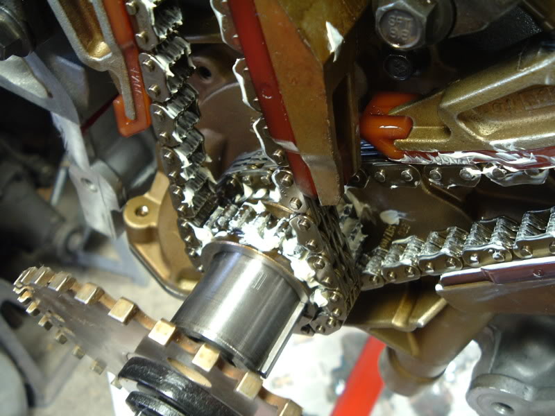
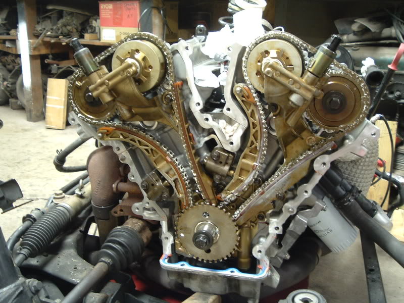
The link counts between marks is as follows:
Crank keyway (starting with the first link away from it) moving clockwise to the intake cam mark = 34 links
Continuing clockwise to the mark on the exhaust cam = 15 links
Moving further clockwise, back to the crank keyway = 19 links.
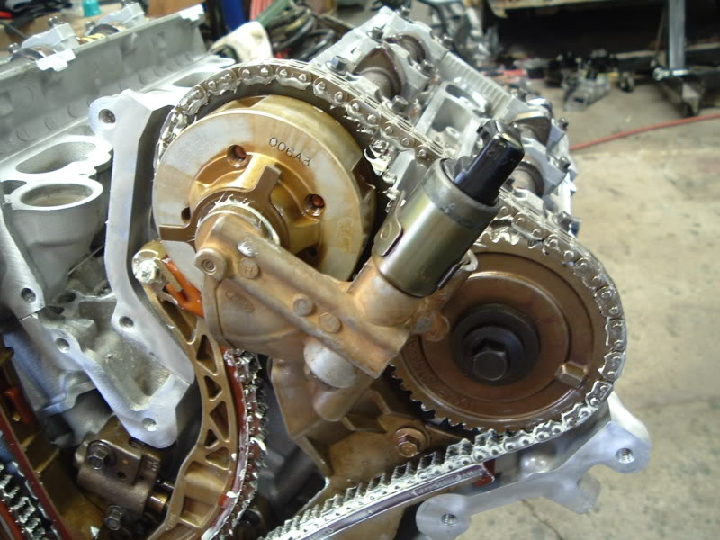
Moving to the REAR bank
Intake
Exhaust
Both.
More to come, including CORRECT timing of this motor.. soon.
It cranks.
And cranks.
And cranks.
It finally fires, runs for 5-6 seconds, and stalls out with a buck, and wouldn't restart. It cranked very roughly, burped out of the intake, and just didn't sound good. The timing was off. Apparently I had too much faith in the accuracy of the JTIS timing instructions, and the advice given on the 3 liter motor blog. They're wrong. WRONG. After all of this work, I'm screwed up by someone's else bs instructions. Whoever wrote the JTIS section on timing for the X-type should HANG.
As of now it's throwing tons of codes, Cruise Not Available, Gearbox Fault, DSC system fault, CEL, and both red and yellow lights.
The gearbox and DSC messages kind of throw me off.. Even with motor problems, I didn't expect those. I know there's really nothing wrong with the tranny as it was just replaced a year ago, and hasn't acted up at all.
Long story short, here it is tonight. After removing the engine for the SECOND time, I'm going to tackle the timing tomorrow.
I pulled the valves covers, accessories, pullies, and front cover to get to what I needed to, without putting it back on the stand or removing the oil pan (just the front two pan bolts).
As it is now.. I know the rear bank is 180 out, so here's the front bank which I think may be alright (but I'm doubtful....James?)
Crank keyway at 3 on the dot.
Front bank exhaust cam timing mark.
Front bank intake timing mark near the "top." My finger is touching the link that is centered over the timing mark.
Both front bank cams, exhaust dot visible, see finger for location of intake dot.
The link counts between marks is as follows:
Crank keyway (starting with the first link away from it) moving clockwise to the intake cam mark = 34 links
Continuing clockwise to the mark on the exhaust cam = 15 links
Moving further clockwise, back to the crank keyway = 19 links.
Moving to the REAR bank
Intake
Exhaust
Both.
More to come, including CORRECT timing of this motor.. soon.
Last edited by 310jag; 04-05-2009 at 12:12 AM.
#20
04-05-2009, 02:09 PM
Veteran Member
Join Date: Nov 2006
Location: Glasgow, Scotland UK
Posts: 47,304
Received 9,005 Likes
on
4,113 Posts