
3.0 engine rebuild and re-install FAQ

#22
 04-08-2009, 08:15 AM
I deviate from my orientation of the engine from looking at it as left and right from the back of the motor to looking at it from the front as you would have it on a stand while working on it as to cut down on the mental conversion it takes to get position. LOOKING HEAD ON, STRAIGHT AT FRONT OF ENGINE
Jag310 used the previous post #15 "Timing??? Say What????" to set timing on his engine.
I heard his kitty purring with extreme contentment last night. Way to go 310!!! Still wnat to sell it???? Engine with 0 miles. Should have some value.
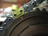
These marks are good and reliable. Make sure #2 and #5 are TDC when you have the Crank key at 3 o'clock. When I get mine assembled I will document the "counting" of the links, i.e. which link is 1 and which link is 33, 15 or 22 to help clear up the counting method.
What is important. Both the left side and the right side are identical positions, just different CAMs. The left exhaust 11 o'clock becomes the right intake at 11 o'clock. The left intake 4 o'clock becomes the right exhaust 4 o'clock. Using this method you can place BOTH chains on at the same time.
Jag310 used the previous post #15 "Timing??? Say What????" to set timing on his engine.
I heard his kitty purring with extreme contentment last night. Way to go 310!!! Still wnat to sell it???? Engine with 0 miles. Should have some value.
These marks are good and reliable. Make sure #2 and #5 are TDC when you have the Crank key at 3 o'clock. When I get mine assembled I will document the "counting" of the links, i.e. which link is 1 and which link is 33, 15 or 22 to help clear up the counting method.
What is important. Both the left side and the right side are identical positions, just different CAMs. The left exhaust 11 o'clock becomes the right intake at 11 o'clock. The left intake 4 o'clock becomes the right exhaust 4 o'clock. Using this method you can place BOTH chains on at the same time.
Last edited by jfenley; 04-08-2009 at 09:23 AM.
#23
05-04-2009, 06:06 PM
I finally have all the CORRECT parts to start my engine rebuild. If you followed the removal thread you can see by its date that my engine has been out for awhile. I opened it up to find out what happened. I found LOTS of gray oil and bits of metal in the oil sump/pan. I did not receive ANY idiot lights telling me something was wrong. So what was the damage? ALL my connecting rods were stiff, to the point I could put them at a 25 to 30 degree angle and the rod would stay in that position. I had a bearing in cylinder # 6 that had spun and welded itself together. I had glitter in the VVT oil screens. I had a damaged rod from #6 and the mains on the crank were were just a little rough. I did not have any �burn� marks anywhere. I tried to have a machine/engine builder shop take the engine and restore it to health again. After over a month, maybe six weeks, I was told they were not comfortable doing the rebuild. During that time they had hot tanked the parts and turned, balanced and straightened the crank, .010 on the mains and .020 on the rods. So it was up to me now to rebuild this machine. After reading the rebuild instructions many times I began to get a feel of what was to be considered �approach with caution� and what was �important�. Up to this point I have done a few engine jobs, replace timing chain in a Datsun 4 cyl truck, replaced rods and rings in a 3 cyl Geo Sprint and a complete rebuild of a Toyota 4 cyl truck which had a bent rod. All but one of these turned out fine, with some calamity along the way. The Toyota was rebuilt after about 1 year of sitting dismantled. I was not in a good place, my wife past shortly after I tore it down and I never got back to it. After I did, I made a mistake of not putting in a plug in the front main oil galley so I had no oil pressure. It was shooting out that hole into the front cover. After that repair, all was good for about 2 weeks and then I got I knock of a rod. I sold the thing as-is, in frustration. The new owner dropped the oil pan and discovered the rod bearing had become dislodged. He replaced the bearing and it is still running today. I say all this because I do not what anyone to think I am a highly skilled mechanic and have rebuilt several engines. My line of work is computer hardware and networking not mechanics.
#24
05-04-2009, 06:58 PM
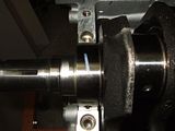
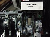
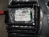
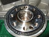
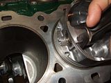
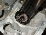
I began the rebuild with the crank. I carefully mic�d the crank and the old bearings, then the new bearings, that were supposed to be 25mm oversized mains and 50mm oversized rods. I then checked the math to see if the new bearings would fit correctly.
 Click on image for larger size
I then dry fitted the original bearings and used plasti-gauge to check original clearance ( + ) the amount that had been taken away from the crank. This was my only reference data since I had no specs to work with. After I had the results I could not get any �clear� answers as to the bearing clearance.
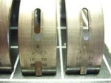
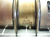
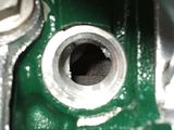
I decided that I had to trust my machinist on the crank and use the oversized bearing. But oversized from what? Bearing size #1, #2 or #3. My block was marked with �2� pointing at the three cyl to the left and right. There was also a Stamp on the back of the block that had 2S2222.
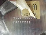
I learned that these are the codes for the bearing sizes. There was also supposed to be one on the back of the crank, it was not there anymore.
CRANKSHAFT CODE / BLOCK CODE
1. READ THE ELEVEN CHARACTER CODES ON THE CYLINDER BLOCK FACE
AND THE CRANKSHAFT FLANGE. THEY ARE ARRANGED AS FOLLOWS:
*####*####*. THE FIRST TWO NUMBERS AFTER THE FIRST ASTERISK
MAKE UP THE CODE FOR MAIN #1 AND THE NEXT TWO NUMBERS FOR
MAIN #2. THE FIRST TWO NUMBERS AFTER THE SECOND ASTERISK
MAKE UP THE CODE FOR MAIN #3 AND THE LAST TWO NUMBERS FOR
MAIN #4.
2. LOOK AT THE SELECT−FIT CHART BELOW AND FOR EACH MAIN, MATCH
THE BLOCK AND CRANKSHAFT CODE WITH ITS CORRESPONDING COLUMN
OR ROW. BY READING ACROSS THE CRANKSHAFT ROW AND DOWN THE
BLOCK COLUMN, SELECT THE PROPER GRADE BEARING FOR EACH MAIN.
(E.G. IF THE BLOCK CODE IS *0609*0711* AND THE CRANKSHAFT CODE
IS *8480*8082*, MAIN #1 SHOULD BE BUILT WITH GRADE 1 BEARINGS, AS
DETERMINED BY THE INTERSECTION OF THE 06 BLOCK COLUMN AND THE 84 CRANKSHAFT ROW. MAINS 2,3, AND 4 SHOULD ALL BE GRADE 2.)
SELECT−FIT MAIN BEARING GRADE CHART
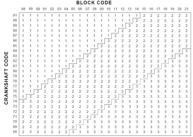
This chart is from the -543-FORD Assembly Chart 2001 for 3.0L Tau/Sab. (NOTE: not positive this is the correct chart. I think TAU is Tarus and SAB is Sable)
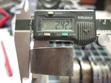
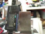
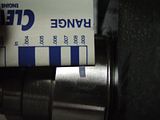
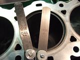
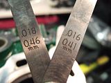
So now what? I looked at the old bearing and it�s thickness mic�d in at what the #2 size bearing mic�d. (Note: You need a dome mic to properly mic curved surface. I used both types and ended up with the same readings.) I had earlier purchased the Jaguar #2 bearing size. So it would appear that my engine had #2 bearing size, which mic�d at .09 and my 25mm oversize bearing mic�d .103. At this point I felt I could move ahead. Why the trouble? The bearings are �size to fit�. Translated in my mind as the mains could have a combination of bearing sizes, #1, #2 and #3. After feeling more confident that ALL my original bearings were #2 I felt the 25mm oversized bearings were indeed the correct main bearings so I proceeded to place on the bed/girdle and bolt it down with $400 worth of ALL NEW BOLTS that were required. I then installed my rear oil seal. I installed the new oil pump.
I will post more in the days to come, covering
"RODS, PISTONS & RINGS",
"HEADs, GASKETS & SEALS",
"TIMING",
and other parts of intrest.


 Click on image for larger size
I then dry fitted the original bearings and used plasti-gauge to check original clearance ( + ) the amount that had been taken away from the crank. This was my only reference data since I had no specs to work with. After I had the results I could not get any �clear� answers as to the bearing clearance.


I decided that I had to trust my machinist on the crank and use the oversized bearing. But oversized from what? Bearing size #1, #2 or #3. My block was marked with �2� pointing at the three cyl to the left and right. There was also a Stamp on the back of the block that had 2S2222.

I learned that these are the codes for the bearing sizes. There was also supposed to be one on the back of the crank, it was not there anymore.
CRANKSHAFT CODE / BLOCK CODE
1. READ THE ELEVEN CHARACTER CODES ON THE CYLINDER BLOCK FACE
AND THE CRANKSHAFT FLANGE. THEY ARE ARRANGED AS FOLLOWS:
*####*####*. THE FIRST TWO NUMBERS AFTER THE FIRST ASTERISK
MAKE UP THE CODE FOR MAIN #1 AND THE NEXT TWO NUMBERS FOR
MAIN #2. THE FIRST TWO NUMBERS AFTER THE SECOND ASTERISK
MAKE UP THE CODE FOR MAIN #3 AND THE LAST TWO NUMBERS FOR
MAIN #4.
2. LOOK AT THE SELECT−FIT CHART BELOW AND FOR EACH MAIN, MATCH
THE BLOCK AND CRANKSHAFT CODE WITH ITS CORRESPONDING COLUMN
OR ROW. BY READING ACROSS THE CRANKSHAFT ROW AND DOWN THE
BLOCK COLUMN, SELECT THE PROPER GRADE BEARING FOR EACH MAIN.
(E.G. IF THE BLOCK CODE IS *0609*0711* AND THE CRANKSHAFT CODE
IS *8480*8082*, MAIN #1 SHOULD BE BUILT WITH GRADE 1 BEARINGS, AS
DETERMINED BY THE INTERSECTION OF THE 06 BLOCK COLUMN AND THE 84 CRANKSHAFT ROW. MAINS 2,3, AND 4 SHOULD ALL BE GRADE 2.)
SELECT−FIT MAIN BEARING GRADE CHART
This chart is from the -543-FORD Assembly Chart 2001 for 3.0L Tau/Sab. (NOTE: not positive this is the correct chart. I think TAU is Tarus and SAB is Sable)
So now what? I looked at the old bearing and it�s thickness mic�d in at what the #2 size bearing mic�d. (Note: You need a dome mic to properly mic curved surface. I used both types and ended up with the same readings.) I had earlier purchased the Jaguar #2 bearing size. So it would appear that my engine had #2 bearing size, which mic�d at .09 and my 25mm oversize bearing mic�d .103. At this point I felt I could move ahead. Why the trouble? The bearings are �size to fit�. Translated in my mind as the mains could have a combination of bearing sizes, #1, #2 and #3. After feeling more confident that ALL my original bearings were #2 I felt the 25mm oversized bearings were indeed the correct main bearings so I proceeded to place on the bed/girdle and bolt it down with $400 worth of ALL NEW BOLTS that were required. I then installed my rear oil seal. I installed the new oil pump.


I will post more in the days to come, covering
"RODS, PISTONS & RINGS",
"HEADs, GASKETS & SEALS",
"TIMING",
and other parts of intrest.
Last edited by jfenley; 05-05-2009 at 09:51 AM.
#25
05-04-2009, 08:01 PM
Veteran Member
Man, later on as the car engine quit on me i was thinking of dropping a 350, v6, or v8 in and switching out the nessacsary components. But too bad i have no idea on the project and the requiremnets, i proabally will let a professional handle the task, let me how the "intense" project goes.
#26
05-05-2009, 08:47 AM
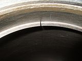
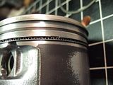
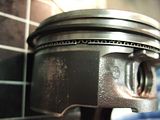
Now moving on after that I started to do the pistons, rod bearings and rings. I sent my pistons out and had new bushings pressed in and honed. I used Power Seal bushings. The machinist, now on my second shop, said the bushings had to have alot honed out of them as to fit. He also said that the old ones had seen catastrophic oil failure or the lack of lubrication all together. Now my pistons are ready to install, moving freely once again. I had decided to measure end-gap of the rings and install the pistons. I purchased Power Seal ring kit for $25 off eBay, normally $142. They were never used and complete. They were the same thickness as the original rings and the end-gap was correct.
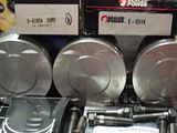
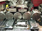
The problem was with the oil ring set. First the corrugated ring would NOT FIT. The wiper rings were the same thickness as originals. I decided to re-use the original corrugated oil ring and the new wiper rings. Feeling a little disappointed I continued to assemble the rings on the pistons and arrange the rings in their staggered positions.
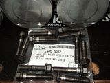
Once the rings were in place I installed the 50mm oversized Power Seal bearings. This is when the gremlins came in late that night and ate half my bearings. I looked for 1 � hrs and could not find the other packet that I had the night before. I loaded 3 pistons with bearings and proceeded to install them. I used my ring compression tool and collapsed the rings as much as I could. I used wood dowels that I threaded on one end, using a die, so I could screw into the rods and guide my rods on the crank.
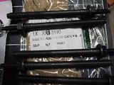
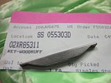
I pressed, tapped and noticed I could not get them to enter the cylinder. It appeared that the oil ring wipers were not compressing. I previously checked the end-gap and it fit within spec. I took a very close look. The wiper rings were free, they were the correct dia. verified by end-gap measurement, thickness was identical to old rings. So what was different? Internal diameter was not the same, by that I mean that the surface area was larger. Now I was going to have to order new rings and place an overnight on them. I tried to order IMC rings but was told the next day that they had no stock, but could substitute with the Power Seal rings. I ended up purchasing rings from Jaguar for $410 and then overnight delivery. I also ordered a new WoodRuff key since my first machinist kindly did not return my original.
The Power Seal ring kit is made for the Power Seal Pistons which comes in various sizes. Don�t make this mistake and order Power Seal , they DO NOT FIT. I spoke to Jag310 during his rebuild and this was his experience also, while he was on the phone I tested the rings on a piston for fit. I did not open them up and install them in their respective groves, I simply took them out and slid them, edge wise into their appropriate grove, even the oil ring and wipers fit that way. At the time I thought maybe mine were different or maybe mine were not the exact rings since I purchased an open box.
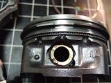
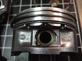
Moving on, once I had the new rings and another set of 50mm oversized rod bearings I removed the Power Seal rings and installed the new ones after verifying that they had the correct end gap. I also installed the final 3 bearings. Remembering how the Toyota bearing came out of its notch I made sure these were well seated. Now these rings went much better. I had no idea which way to put in the 2nd compression ring, it had a step in its profile. The Power Seal sheet said that the taper goes upward toward the top of the piston. Ford assembly manual had a sideways �z� with the taper toward the top.
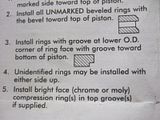
I installed with the flat toward the bottom and the step toward the top. After installing 5 of the 6 pistons I opened the last box. To my surprise there was a FORD wrapper in the package with the installation information. All the previous wrappers were simple brown paper, no instructions.
It turns out that the FLAT goes up with the step toward the bottom. Welcome to the school of hard knocks.
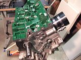
I installed #6 correctly and then bumped the other 5, one at a time, out far enough to get my hands on the 2nd ring and flip it over. Finish the block by installing the Water Pipe Inlet, the knock sensor and the blanking cover. New gaskets and o-rings of course. Feeling confident that I had completed step 2 of this task I moved to the Heads.


The problem was with the oil ring set. First the corrugated ring would NOT FIT. The wiper rings were the same thickness as originals. I decided to re-use the original corrugated oil ring and the new wiper rings. Feeling a little disappointed I continued to assemble the rings on the pistons and arrange the rings in their staggered positions.


Once the rings were in place I installed the 50mm oversized Power Seal bearings. This is when the gremlins came in late that night and ate half my bearings. I looked for 1 � hrs and could not find the other packet that I had the night before. I loaded 3 pistons with bearings and proceeded to install them. I used my ring compression tool and collapsed the rings as much as I could. I used wood dowels that I threaded on one end, using a die, so I could screw into the rods and guide my rods on the crank.

I pressed, tapped and noticed I could not get them to enter the cylinder. It appeared that the oil ring wipers were not compressing. I previously checked the end-gap and it fit within spec. I took a very close look. The wiper rings were free, they were the correct dia. verified by end-gap measurement, thickness was identical to old rings. So what was different? Internal diameter was not the same, by that I mean that the surface area was larger. Now I was going to have to order new rings and place an overnight on them. I tried to order IMC rings but was told the next day that they had no stock, but could substitute with the Power Seal rings. I ended up purchasing rings from Jaguar for $410 and then overnight delivery. I also ordered a new WoodRuff key since my first machinist kindly did not return my original.
The Power Seal ring kit is made for the Power Seal Pistons which comes in various sizes. Don�t make this mistake and order Power Seal , they DO NOT FIT. I spoke to Jag310 during his rebuild and this was his experience also, while he was on the phone I tested the rings on a piston for fit. I did not open them up and install them in their respective groves, I simply took them out and slid them, edge wise into their appropriate grove, even the oil ring and wipers fit that way. At the time I thought maybe mine were different or maybe mine were not the exact rings since I purchased an open box.
Moving on, once I had the new rings and another set of 50mm oversized rod bearings I removed the Power Seal rings and installed the new ones after verifying that they had the correct end gap. I also installed the final 3 bearings. Remembering how the Toyota bearing came out of its notch I made sure these were well seated. Now these rings went much better. I had no idea which way to put in the 2nd compression ring, it had a step in its profile. The Power Seal sheet said that the taper goes upward toward the top of the piston. Ford assembly manual had a sideways �z� with the taper toward the top.


I installed with the flat toward the bottom and the step toward the top. After installing 5 of the 6 pistons I opened the last box. To my surprise there was a FORD wrapper in the package with the installation information. All the previous wrappers were simple brown paper, no instructions.

It turns out that the FLAT goes up with the step toward the bottom. Welcome to the school of hard knocks.


I installed #6 correctly and then bumped the other 5, one at a time, out far enough to get my hands on the 2nd ring and flip it over. Finish the block by installing the Water Pipe Inlet, the knock sensor and the blanking cover. New gaskets and o-rings of course. Feeling confident that I had completed step 2 of this task I moved to the Heads.
Last edited by jfenley; 05-05-2009 at 11:27 AM.
#27
05-05-2009, 09:38 AM
While I waited on my Jaguar rings I tackled the heads. I took the heads to the same shop as the pistons and had the re-vat them and install new FelPro stem seals. I opted not to have the valves & seats touched. This may come back on me later. I had the head stripped down to nothing but the stem seals and valve guides.
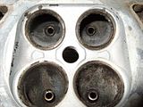
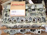
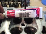
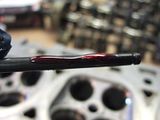
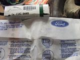
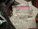
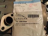
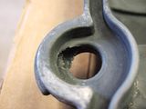
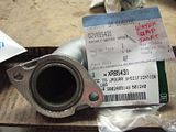
The stem seals gave me an issue removing and I was afraid to grab them with needle nose vice grips. I did not want to damage the valve guides. I carefully re-assembled them and prepped then for install. Head gaskets are also another place to go wrong. I ordered Jaguar gaskets twice. The first time I simply ordered online the head gaskets. The left was correct and the right was different.
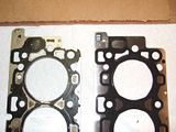
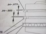
Ordered without VIN. Obvious difference, Left is Original
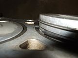
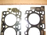
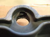
I ordered a second time over the phone using my VIN. The left was correct but the right was only extremely close, all but a small water port through hole. I decided to drill this hole through since it was already on the top side.
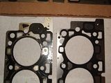
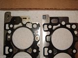
Ordered with VIN. Still not 100%. Original/New bottom, Original/New top. Notice the "hole" is in the New top layer in the last photo. This hole is the one I finished with a drill.
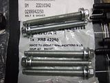
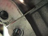
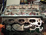
Now my heads and gaskets were ready. I install the Left head and torque it down. I lay the right gasket up on the block and my attention was taken to the large holes at the top of the head gasket and the inside edge of the block. Something is not right! Ah yes, the alignment guides! I looked around for the guides and pressed them into the block. Now the right head was much better, the gasket aligned up no problem and the head did not try to slip off the block. Torqued that head down and removed the left head and installed the alignment guides. Installed new bolts, lucky I ordered 4 sets!
I know I probably could have used the ones I just put in since they have not had any temp cycling but I chose not to chance anything especially with the low cost of the bolts from FelPro.


The stem seals gave me an issue removing and I was afraid to grab them with needle nose vice grips. I did not want to damage the valve guides. I carefully re-assembled them and prepped then for install. Head gaskets are also another place to go wrong. I ordered Jaguar gaskets twice. The first time I simply ordered online the head gaskets. The left was correct and the right was different.


Ordered without VIN. Obvious difference, Left is Original
I ordered a second time over the phone using my VIN. The left was correct but the right was only extremely close, all but a small water port through hole. I decided to drill this hole through since it was already on the top side.


Ordered with VIN. Still not 100%. Original/New bottom, Original/New top. Notice the "hole" is in the New top layer in the last photo. This hole is the one I finished with a drill.
Now my heads and gaskets were ready. I install the Left head and torque it down. I lay the right gasket up on the block and my attention was taken to the large holes at the top of the head gasket and the inside edge of the block. Something is not right! Ah yes, the alignment guides! I looked around for the guides and pressed them into the block. Now the right head was much better, the gasket aligned up no problem and the head did not try to slip off the block. Torqued that head down and removed the left head and installed the alignment guides. Installed new bolts, lucky I ordered 4 sets!

I know I probably could have used the ones I just put in since they have not had any temp cycling but I chose not to chance anything especially with the low cost of the bolts from FelPro.
#28
05-05-2009, 11:23 AM
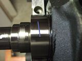
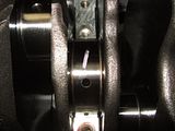
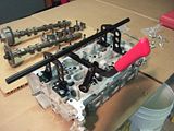
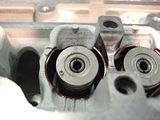
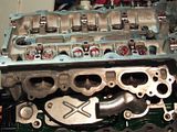
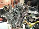
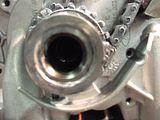
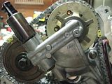
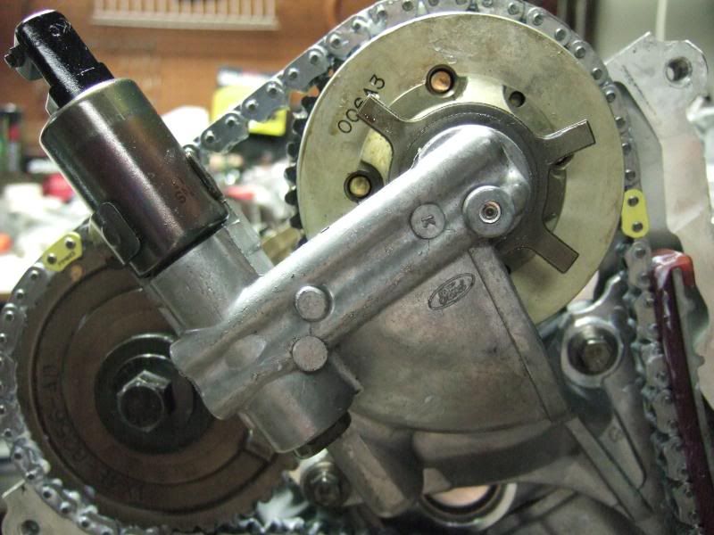
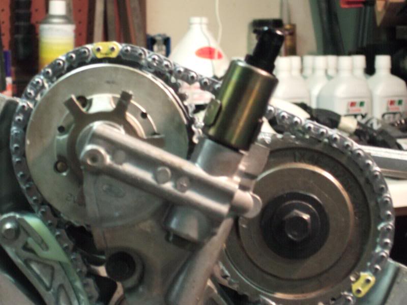
Charging ahead now more focused and refreshed. I moved to the timing chain, tensioners , guides and VVT assembly. I installed the new WoodRuff key and the timing chain gear, turned the crank until #2 piston on the crank and #5 piston on the crank were at TDC and the key is at 3 O�clock.
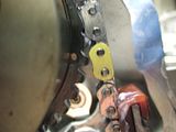
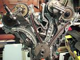
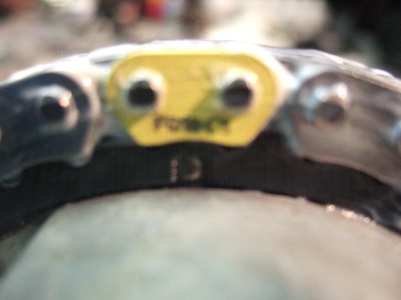
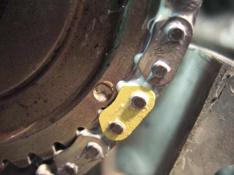
This is the pre-teardown position the engine was at before any timing was touched. I loosened the Intake Cam caps and used a 1� open end wrench to turn the cam mark to the 11 O�clock position. I loosened the caps on the Exhaust Cam and used a socket on the sprocket nut to turn it to the 5 O�clock position. I got the new chain, with 3 bright yellow links, and laid the yellow links on the cam marks and took out the slack.
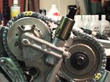


Note: the VVT assembly must be in place and you have to place the right hand, as you are facing the front of the engine on the stand, chain on first. On the VVT assembly be sure to replace the small o-ring that seals to the face of the block. I also installed two new seals on the neck that plugs into the Intake cam sprocket.
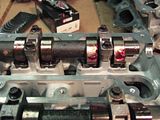
Install the tensioner guide rail and the tensioner itself. Make sure the chain is tight across the cam sprockets and tight from the exhaust cam sprocket to the gear on the crank. DO NOT REMOVE the pin on the tensioner yet. Now set up the cams the same way on the right side. Install the VVT guide rail. Exhaust cam mark at 11 O�clock and Intake at 5 O�clock. Lay the chain on the same way as the right side. This time make sure the chain is tight across the cam sprockets and the Intake sprocket to crank gear is tight. Install the Tensioner guide rail and then the tensioner.
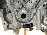
Torque the bolts to correct setting on the guide rails, VVT and also the Tensioners themselves. Now torque the cams down to proper specifications in proper sequence. Assuming you used CAM lube and Assembly lube, dry turn engine a few revolutions, I turned mine well over 15 revolutions until the yellow marks lined up again on the cams (it took forever), SLOWLY to check for binding or constriction. You should be able to turn crank easily. If you experience any binding or hard to turn spots something is wrong and you should investigate. If all is well pull the pin on your tensioners. There is one other item that you will have to install for timing to be complete. The CPK sensor pulse wheel. It is possible to install it 180 degrees out of timing and ruin your day. The JTIS has no documentation on this, that I found. There are two notches cut into the center of the pulse wheel that slide down the crank woodruff key, they are on opposite sides of the wheel, left to right. The proper placement is with teeth facing forward and the �GAP� in the teeth lined up with the crank woodruff key.
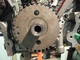
Timing is set. (This section was from my personal experience with my original timing and differs somewhat from the JTIS instructions. JTIS has the WoodRuff key set at 9 0�clock but mine was at 3 O�clock. Jag310 used the above procedure and his engine purred. I don�t think JTIS is wrong, but rather the procedure they describe is difficult to follow and understand for a novice like myself.)


This is the pre-teardown position the engine was at before any timing was touched. I loosened the Intake Cam caps and used a 1� open end wrench to turn the cam mark to the 11 O�clock position. I loosened the caps on the Exhaust Cam and used a socket on the sprocket nut to turn it to the 5 O�clock position. I got the new chain, with 3 bright yellow links, and laid the yellow links on the cam marks and took out the slack.


Note: the VVT assembly must be in place and you have to place the right hand, as you are facing the front of the engine on the stand, chain on first. On the VVT assembly be sure to replace the small o-ring that seals to the face of the block. I also installed two new seals on the neck that plugs into the Intake cam sprocket.


Install the tensioner guide rail and the tensioner itself. Make sure the chain is tight across the cam sprockets and tight from the exhaust cam sprocket to the gear on the crank. DO NOT REMOVE the pin on the tensioner yet. Now set up the cams the same way on the right side. Install the VVT guide rail. Exhaust cam mark at 11 O�clock and Intake at 5 O�clock. Lay the chain on the same way as the right side. This time make sure the chain is tight across the cam sprockets and the Intake sprocket to crank gear is tight. Install the Tensioner guide rail and then the tensioner.


Torque the bolts to correct setting on the guide rails, VVT and also the Tensioners themselves. Now torque the cams down to proper specifications in proper sequence. Assuming you used CAM lube and Assembly lube, dry turn engine a few revolutions, I turned mine well over 15 revolutions until the yellow marks lined up again on the cams (it took forever), SLOWLY to check for binding or constriction. You should be able to turn crank easily. If you experience any binding or hard to turn spots something is wrong and you should investigate. If all is well pull the pin on your tensioners. There is one other item that you will have to install for timing to be complete. The CPK sensor pulse wheel. It is possible to install it 180 degrees out of timing and ruin your day. The JTIS has no documentation on this, that I found. There are two notches cut into the center of the pulse wheel that slide down the crank woodruff key, they are on opposite sides of the wheel, left to right. The proper placement is with teeth facing forward and the �GAP� in the teeth lined up with the crank woodruff key.


Timing is set. (This section was from my personal experience with my original timing and differs somewhat from the JTIS instructions. JTIS has the WoodRuff key set at 9 0�clock but mine was at 3 O�clock. Jag310 used the above procedure and his engine purred. I don�t think JTIS is wrong, but rather the procedure they describe is difficult to follow and understand for a novice like myself.)
Last edited by jfenley; 05-05-2009 at 11:40 AM.
The following users liked this post:
TR64ever (06-22-2016)
#29
05-06-2009, 08:45 AM

great reporting..
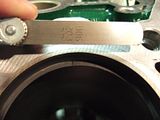
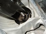
since i love to nit pick (hehe) the picture of measuring the main bearing shells, shows a digital vernier caliper - not a micrometer....
also the shells are curved, and the faces of the caliper are flat, so the measurement is for sure not accurate. The plastigauge should get everything right, but I dont like to see people miss-lead on some stuff..
thanks for all your work here,, keep it coming, I appreciate it.
#30
05-06-2009, 10:47 AM
Jimmy,
Yes, the image shows the digital verneir, only because I was getting the same readings with my dome mic. The point was not to mislead but to inform that there are varing tolerances that can be seen IF your bearings are mixed. The Verneir gave me a consistant reading over a larger surface area throughout my bearings, verifying that they were indeed identical to each other. It also allowed me to see that my original bearings were the #2 Jaguar bearing. Jaguar, as far as I could find, does not have "sizes" in amount "oversized". I also could not find any information on tolerances and cleareances for the mains, crank, or rods. I did use Plasti-guage and dry crush brearings, but this was only to see how close I was to the "original" set.
Yes, the image shows the digital verneir, only because I was getting the same readings with my dome mic. The point was not to mislead but to inform that there are varing tolerances that can be seen IF your bearings are mixed. The Verneir gave me a consistant reading over a larger surface area throughout my bearings, verifying that they were indeed identical to each other. It also allowed me to see that my original bearings were the #2 Jaguar bearing. Jaguar, as far as I could find, does not have "sizes" in amount "oversized". I also could not find any information on tolerances and cleareances for the mains, crank, or rods. I did use Plasti-guage and dry crush brearings, but this was only to see how close I was to the "original" set.
#31
05-22-2009, 09:27 AM
This is the section for some of the pieces that mount to the Block to finish your assembly.
Install the Oil Pan Baffle before the Pick-Up tube, should use new nuts.
Oil Pick-Up tube, Install new o-ring seal on the oil pick-up tube.
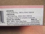
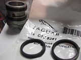
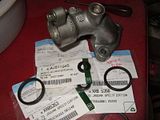
Valve Covers, new gaskets for the Valve Covers and new rubber. I made the MISTAKE of removing the VVT solenoid seal in the Valve Cover. Jaguar DOES NOT sell this part separately for the X-Type and the S-Type seal DOES NOT FIT. I had to order a new Valve Cover for the Left side. During disassembly I noticed that the right one had a damaged hole and was cracked horizontally in the boss. I had to also replace the right.
Two new valve covers. Just so you know, they come with the bolts and both inner and outer seals and of course the VVT solenoid seal.
PVC Valve, I picked up a new PVC valve. This is a TWIST on lock type PVC with an o-ring seal. There are two plastic spring �d-tents� that you must seat into the Valve cover. Twist PVC in until the d-tents lock into their respective indents. This is the locked position. While turning in mine, it felt as if it was turned as far as you could turn. I grabbed the old unit and made sure that they were identical. I then proceeded to turn it past where it felt it was stopped and sure enough it moved past that position and the d-tents dropped into the indents.
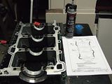
Front Cover, 4 new seals, the left, inner, right and the front main oil seal. Be sure to place a dab of gasket sealer over the union of the various block parts, ie the bed/girdle to block, the heads to block.
I even placed a dab at the top or the heads to make sure I made a good seal here also. I almost forgot about the INNER seal section. With things going together a bit more smoothly I became distracted and was looking father down the road than my current task. Don�t let this slip by your attention. Start with the inner seal area first.
Engine Mount, mine was rusty and was not easy to remove during tear down. I cleaned the back side and coated the contact points with anti-seize. On the outside a fresh coat of paint.
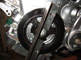
Pulleys, If you want you can get new bearings and have them pressed in to renew their longevity I also gave them a fresh coat of paint. The belt tensioner Pulley was removed and I used a fine wire wheel on a buffer to clean up and brighten the assembly. The pulley bearing is a good candidate for replacement.
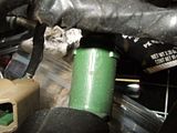
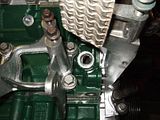
Water Pipes, the top of the block has a water pipe inlet with the water temp sensor on it. Be sure to replace the seals there including the water temp sensor seal.
This is the location I plan to place a �T� to install a gauge, so I may use pipe tape or pipe dope to make my seal. The Temp seal face presses firmly on a metal washer like material with a rubber mat attached.
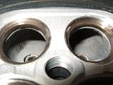
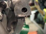
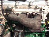
Fuel Injectors, Inspect ALL injectors for damage. Mine had cracks on the boss of the injector.
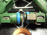
Although this is a minor issue solved with some black electrical tape, I chose to replace them all. The reason for replacement was the prevention of moisture entering the boss and causing the injector to become damaged more. I was told from a friend that these injectors must have seen some real heat to crack the boss, so be aware that electrical tape may not stay tight. You should also replace the O-ring seals.
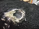
Wiring Harness, I had a crispy, crackling harness. I removed all the electrical tape from the harness and renewed it with a fresh wrap. I used a Scotch brand that was good up to 194�F temp. I also used the adhesive type muffler tape, with fiberglass, to wrap areas that were in or near the heat of the Exhaust.
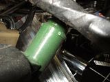
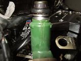
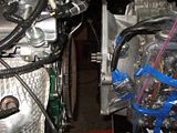
Gage add-ons, Oil Pressure, I located an oil galley below the Power Steering pump.
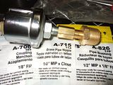
Due to the heat in this location I wrapped my sender in muffler tape as well as the wire. Water Temp, I was tempted to place a �T� on the factory location until I carefully examined the �tip� of the factory sending unit. It is mounted in the flow of the water. I figured if I moved it out of the flow I might throw some signal out of range or worse cause it to read cooler. I chose to have a bung welded onto the water outlet pipe that connects the block to the water pump. I had this one set in the flow also. Tranny Temp, I had a bung welded to the bottom right corner of the black pan mounted to the tranny. This will not necessarily give me a true reading but it will allow me to monitor a rise in temperature. Thoughts, I could have simply �spliced� into the electrical wiring of the harness at the Oil pressure sender, Water temp sender, and the Tranny temp sender but I know that the Vehicle Computer looks at small voltage differences to make it�s adjustments. Adding resistance and a voltage drop due to the �Extra� wire spliced into the sending units MIGHT throw the readings out of range. I chose to be safe. Believe it or not, you have an Oil Pressure sender, Oil Temp sender, Water Temp sender and a Transmission Temp sender already on that powertrain. It would have been nice if Jaguar/Ford would have cluttered up the Instrument Cluster with some �live� gages.
Install the Oil Pan Baffle before the Pick-Up tube, should use new nuts.
Oil Pick-Up tube, Install new o-ring seal on the oil pick-up tube.

Valve Covers, new gaskets for the Valve Covers and new rubber. I made the MISTAKE of removing the VVT solenoid seal in the Valve Cover. Jaguar DOES NOT sell this part separately for the X-Type and the S-Type seal DOES NOT FIT. I had to order a new Valve Cover for the Left side. During disassembly I noticed that the right one had a damaged hole and was cracked horizontally in the boss. I had to also replace the right.


Two new valve covers. Just so you know, they come with the bolts and both inner and outer seals and of course the VVT solenoid seal.
PVC Valve, I picked up a new PVC valve. This is a TWIST on lock type PVC with an o-ring seal. There are two plastic spring �d-tents� that you must seat into the Valve cover. Twist PVC in until the d-tents lock into their respective indents. This is the locked position. While turning in mine, it felt as if it was turned as far as you could turn. I grabbed the old unit and made sure that they were identical. I then proceeded to turn it past where it felt it was stopped and sure enough it moved past that position and the d-tents dropped into the indents.
Front Cover, 4 new seals, the left, inner, right and the front main oil seal. Be sure to place a dab of gasket sealer over the union of the various block parts, ie the bed/girdle to block, the heads to block.


I even placed a dab at the top or the heads to make sure I made a good seal here also. I almost forgot about the INNER seal section. With things going together a bit more smoothly I became distracted and was looking father down the road than my current task. Don�t let this slip by your attention. Start with the inner seal area first.
Engine Mount, mine was rusty and was not easy to remove during tear down. I cleaned the back side and coated the contact points with anti-seize. On the outside a fresh coat of paint.
Pulleys, If you want you can get new bearings and have them pressed in to renew their longevity I also gave them a fresh coat of paint. The belt tensioner Pulley was removed and I used a fine wire wheel on a buffer to clean up and brighten the assembly. The pulley bearing is a good candidate for replacement.
Water Pipes, the top of the block has a water pipe inlet with the water temp sensor on it. Be sure to replace the seals there including the water temp sensor seal.


This is the location I plan to place a �T� to install a gauge, so I may use pipe tape or pipe dope to make my seal. The Temp seal face presses firmly on a metal washer like material with a rubber mat attached.
Fuel Injectors, Inspect ALL injectors for damage. Mine had cracks on the boss of the injector.


Although this is a minor issue solved with some black electrical tape, I chose to replace them all. The reason for replacement was the prevention of moisture entering the boss and causing the injector to become damaged more. I was told from a friend that these injectors must have seen some real heat to crack the boss, so be aware that electrical tape may not stay tight. You should also replace the O-ring seals.
Wiring Harness, I had a crispy, crackling harness. I removed all the electrical tape from the harness and renewed it with a fresh wrap. I used a Scotch brand that was good up to 194�F temp. I also used the adhesive type muffler tape, with fiberglass, to wrap areas that were in or near the heat of the Exhaust.
Gage add-ons, Oil Pressure, I located an oil galley below the Power Steering pump.


Due to the heat in this location I wrapped my sender in muffler tape as well as the wire. Water Temp, I was tempted to place a �T� on the factory location until I carefully examined the �tip� of the factory sending unit. It is mounted in the flow of the water. I figured if I moved it out of the flow I might throw some signal out of range or worse cause it to read cooler. I chose to have a bung welded onto the water outlet pipe that connects the block to the water pump. I had this one set in the flow also. Tranny Temp, I had a bung welded to the bottom right corner of the black pan mounted to the tranny. This will not necessarily give me a true reading but it will allow me to monitor a rise in temperature. Thoughts, I could have simply �spliced� into the electrical wiring of the harness at the Oil pressure sender, Water temp sender, and the Tranny temp sender but I know that the Vehicle Computer looks at small voltage differences to make it�s adjustments. Adding resistance and a voltage drop due to the �Extra� wire spliced into the sending units MIGHT throw the readings out of range. I chose to be safe. Believe it or not, you have an Oil Pressure sender, Oil Temp sender, Water Temp sender and a Transmission Temp sender already on that powertrain. It would have been nice if Jaguar/Ford would have cluttered up the Instrument Cluster with some �live� gages.
#32
05-22-2009, 09:51 AM
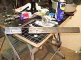
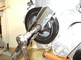
Custom Tool, I made this tool to hold the Crank Pully in place while torquing bolt. This is easy to build and takes very little skill to make. I used ground down Allen wrench shaft for pegs. The allen wrench in question was round except for about 1/2" from the ends.
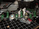
Exhaust, As for myself, I know that the engine bay is very hot and a lot of that heat is from those cats packed into the compartment. I decided to use Exhaust wrap on the headers, cats and pipes. I used 1� wide wrap on the headers and 2� on the pipes and cats. The trick I learned here was not to cut the wrap but to make a continuous wrap. First I wire brushed the headers and the rusted steel on the ends of the Cats. I used MEK to clean the metal, being very careful with the CATS as not to allow foreign chemicals and or material to enter the chamber. I then used 1500�F paint I picked up with the Exhaust wrap and painted the components. Be sure to mask over the Flanges and bung for the O2 sensor. (Another trick here is to leave the tape over the bung hole for the 02 sensor while you wrap the CAT. Later, after the water soaked wrap has dried and you need to cut the hole through the Fiber wrap you will be glad to have that tape in place. It will keep out the foreign material of the fibers from entering the CAT.)
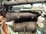
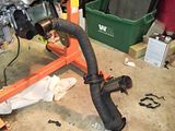
I had a bucket of water and spooled out 10 or 15 feet of wrap into the water. I then proceeded to wrap each component with a single length. This worked well for me. I tried the dry wrap/cut method and could never wrap it the same way after I soaked the wrap. I allowed the continuous wrap to dry and then using the High Temp paint, painted/sealed them. Overall I think it was a success. As for the �Flange� unions and pipe unions I used the adhesive muffler tape to cover these areas after Exhaust was assembled.
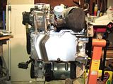
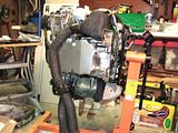
Marring Engine and Transmission, First I put 1 qt of fluid into the Torque converter. While that was settling I hoisted the Transmission onto a Table/Work bench that was about 30� high. I leveled the Transmission and gently inserted the Torque Converter after checking the alignment flats inside the Transmission. I pressed the Torque Converter into the Transmission and turned it but could not get it to completely drop in place. I tried a second turn and still no drop. Then, while I was wondering how to do this task, I placed my hand on the front of the Converter and clunk, it dropped into place. Now with the Engine on the hoist I lined up the Bell Housing to the Transmission alignment sleeves on the block.
I did not mention that the Fly Wheel was already on and torque to spec. It is very important that the engine be level on the hoist. It took several tries before I had the chains just right. Rolled the motor to the Transmission and installed the most of the bolts. There are a few bolts that go through brackets that were not installed yet. Once the Transmission is mounted add some chains to it and lift the whole powertrain as one unit. NOTE: My engine was complete with exhaust and accessories before I mounted to Transmission. My Transfer Case was not attached to my Transmission. This caused me to have to take off the rear CAT and the cross tube just to mount the Transfer Case. You should mount the Transfer Case to the Transmission BEFORE you marry the Engine and Transmission. My final assembly was to torque the 4 Torque converter bolts to the Flywheel, torque the Transmission bolts and install the Starter and torque to spec.
PLUMBING, I proceeded to install the water pipes and hoses and installed new Thermostat. Be sure to use fresh O-rings. This is as far as the assembly can go without putting the powertrain back into the car.
So what�s next? I will try something different. We have a three day weekend. I am going to try an OVERHEAD install of the power train. It looks like it is possible. If it works then getting engine in and out would not be MAJOR work on your back. I plan to mount and align my sub-frame first. Remove the hood and attempt to �Lower� powertrain onto their mounts. There are only 4 connections to the sub-frame. 1st is your Power Steering Pump line, 2nd is the Anti-roll Restrictor, 3rd and 4th are indirect and that is the half-shafts (front axels). My wheel hubs/shock towers are not mounted to the sub frame currently. I think it will not be too difficult to mount them after the sub-frame and Powertrain are installed. Look for the RE-INSTALL post in this thread next week.


Exhaust, As for myself, I know that the engine bay is very hot and a lot of that heat is from those cats packed into the compartment. I decided to use Exhaust wrap on the headers, cats and pipes. I used 1� wide wrap on the headers and 2� on the pipes and cats. The trick I learned here was not to cut the wrap but to make a continuous wrap. First I wire brushed the headers and the rusted steel on the ends of the Cats. I used MEK to clean the metal, being very careful with the CATS as not to allow foreign chemicals and or material to enter the chamber. I then used 1500�F paint I picked up with the Exhaust wrap and painted the components. Be sure to mask over the Flanges and bung for the O2 sensor. (Another trick here is to leave the tape over the bung hole for the 02 sensor while you wrap the CAT. Later, after the water soaked wrap has dried and you need to cut the hole through the Fiber wrap you will be glad to have that tape in place. It will keep out the foreign material of the fibers from entering the CAT.)


I had a bucket of water and spooled out 10 or 15 feet of wrap into the water. I then proceeded to wrap each component with a single length. This worked well for me. I tried the dry wrap/cut method and could never wrap it the same way after I soaked the wrap. I allowed the continuous wrap to dry and then using the High Temp paint, painted/sealed them. Overall I think it was a success. As for the �Flange� unions and pipe unions I used the adhesive muffler tape to cover these areas after Exhaust was assembled.
Marring Engine and Transmission, First I put 1 qt of fluid into the Torque converter. While that was settling I hoisted the Transmission onto a Table/Work bench that was about 30� high. I leveled the Transmission and gently inserted the Torque Converter after checking the alignment flats inside the Transmission. I pressed the Torque Converter into the Transmission and turned it but could not get it to completely drop in place. I tried a second turn and still no drop. Then, while I was wondering how to do this task, I placed my hand on the front of the Converter and clunk, it dropped into place. Now with the Engine on the hoist I lined up the Bell Housing to the Transmission alignment sleeves on the block.


I did not mention that the Fly Wheel was already on and torque to spec. It is very important that the engine be level on the hoist. It took several tries before I had the chains just right. Rolled the motor to the Transmission and installed the most of the bolts. There are a few bolts that go through brackets that were not installed yet. Once the Transmission is mounted add some chains to it and lift the whole powertrain as one unit. NOTE: My engine was complete with exhaust and accessories before I mounted to Transmission. My Transfer Case was not attached to my Transmission. This caused me to have to take off the rear CAT and the cross tube just to mount the Transfer Case. You should mount the Transfer Case to the Transmission BEFORE you marry the Engine and Transmission. My final assembly was to torque the 4 Torque converter bolts to the Flywheel, torque the Transmission bolts and install the Starter and torque to spec.
PLUMBING, I proceeded to install the water pipes and hoses and installed new Thermostat. Be sure to use fresh O-rings. This is as far as the assembly can go without putting the powertrain back into the car.
So what�s next? I will try something different. We have a three day weekend. I am going to try an OVERHEAD install of the power train. It looks like it is possible. If it works then getting engine in and out would not be MAJOR work on your back. I plan to mount and align my sub-frame first. Remove the hood and attempt to �Lower� powertrain onto their mounts. There are only 4 connections to the sub-frame. 1st is your Power Steering Pump line, 2nd is the Anti-roll Restrictor, 3rd and 4th are indirect and that is the half-shafts (front axels). My wheel hubs/shock towers are not mounted to the sub frame currently. I think it will not be too difficult to mount them after the sub-frame and Powertrain are installed. Look for the RE-INSTALL post in this thread next week.
The following users liked this post:
TR64ever (06-22-2016)
#33
05-22-2009, 11:08 AM
Veteran Member
Join Date: Nov 2006
Location: Glasgow, Scotland UK
Posts: 47,303
Received 9,005 Likes
on
4,113 Posts

James.....your posts are just awesome

so detailed and informative as are 310's......a real credit and help to this site as well as others I'm sure......keep it comming big guy
Your info on the engine / electricals / links / parts etc etc etc were all posted by on your behalf and have been made FAQ........Once again, thanks on behalf of all the members

#35
05-22-2009, 04:08 PM
RacerX,
I would LOVE to get rid of the stock headers and cats. The problems I am sure that would arise are the O2 sensor readings to the ECU. This would require an ECU custom program. I live in FORD and CHEVY TRUCK town USA, Oklahoma. I haven't found anyone around that has the knowledge and experience to do the job required. If I'm not mistaken, I believe you can out-fit Mazda RX-7 headers to the manifold and then have a muffler shop bend/weld the rest. I am un-aware of any off-the-shelf solutions. I've seen some of your posts and have admired what you have done to your cat. Correct me if I'm wrong but I think I remember you had re-done your exhaust and re-programmed your ECU. I hold back on the exhaust because another $2k is not what I want to put into this cat right now.
If you know of an off-the-shelf exhaust replacement I would be grateful to know. Also if you know who can re-program the ECU this info would also be good to have.
I have purchased a couple of items that might allow me to flash my ROM. I purchased the AutoEnguinity code reader for its interface to the PC and I purchased a Jag programming CD that requires a red or blue interface to the ACL. I am hoping to be able to use the AutoEnguinity interface to the ACL and maybe the Jag software will see the interface. If not I have a great diagnostic tool/data logger.
You guys are GREAT!!
#36
05-22-2009, 10:00 PM
#38
05-23-2009, 10:54 AM

When you timed the engine, you bought 2 new timing chains with the marks on them. Now my question is; have you counted how many links are there on a chain and how many links are they apart? If you could help me on this, I will not have to go spend money to buy new chains. Any help will be appreciated on this. I am planning on painting the links that you may point out and get the timing right hopefully. becuase I really dont want to fail this second time around.
Last edited by southwest; 05-23-2009 at 11:15 AM.
#39
05-25-2009, 05:13 PM
Southwest,
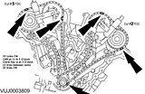
Fired mine back up today. Sounds healthy and strong. Timming with JITS was too difficult for mr to follow. This is what I reccommend.

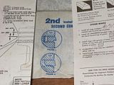
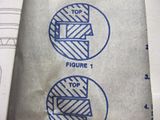
This image translates to:
Left Side
Right Side


THIS IS VERY IMPORTANT.


Try this post for more info https://www.jaguarforums.com/forum/s...0&postcount=15
Also https://www.jaguarforums.com/forum/s...7&postcount=28
Hope this helps.
Fired mine back up today. Sounds healthy and strong. Timming with JITS was too difficult for mr to follow. This is what I reccommend.
This image translates to:
Left Side
Right Side
THIS IS VERY IMPORTANT.
Try this post for more info https://www.jaguarforums.com/forum/s...0&postcount=15
Also https://www.jaguarforums.com/forum/s...7&postcount=28
Hope this helps.
Last edited by jfenley; 05-25-2009 at 05:21 PM.
#40
05-26-2009, 05:12 PM
Thanks for the help Jfenley. My problem from begining was , not being able to start the car. I thought of couple of possibilities, either head gasket wasnt torqued right and second was incorrect timing. now with the pictures you posted I ve did the timing for 4 times on both heads and my compression is still 90psi in 4 cylinders, one cylinder puts out about 120psi and last one is 160psi. so right now, I am planning of removing the heads one more time and get new gaskets and install them with new bolts and torque them one more time.