
Adding a transfer box low drain point
#1
 11-02-2013, 06:12 PM

As asked in another thread, this is an account of how I added an additional drain point to my transfer gearbox plus how I refill it. But first a disclaimer! What follows is an account of what I have done to my own car to solve my own problems. What I have done is unlikely to be approved by Jaguar. Anyone who copies any of my actions or utilises any of the data does so entirely at their own risk and I cannot accept any responsibility for any problems or failures in any car arising from anyone copying my actions, or trying to do so.
First move was to jack the car up and put the front offside jacking point on an axle stand at a height of 16 inches. (This was done in the days before the idea of raising one side to empty and one to fill had become generally known!) The angle this puts the car at assists in effective draining of the oil and is high enough to get at everything necessary.
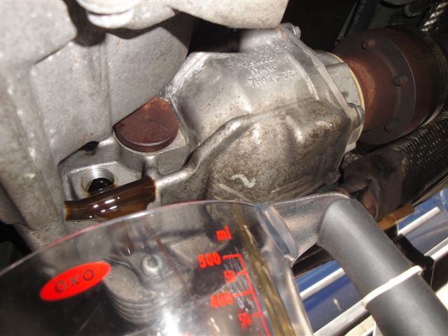
Now here's the first photo:

It shows my home made non return valve fitted instead of the original drain plug in place with its end plug fitted, ie my normal running configuration for the last two years. I'll come back to this valve later on, but I custom made it to suit the limited space available with an auto box.
The second photo shows the non return valve removed and the one year old, chocalate coloured 6000 mile oil draining. When all but the last few drips were collected, any remaining oil was left at the level of the bottom of drain orifice. I got about 200 mls out from here.
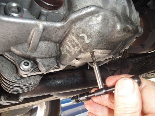
Now not many might wish to make the next move! I considered removing the pinion housing at the back of the 'box to enable the remainder of the oil to drain out, as is recommended in JTIS, but as this requires removal of the rear drive shaft and of course disturbing the transfer box pinion in its mesh with the countershaft, I felt this might create as many problems as it solved. So I spent a lot of time studying the 'box and checking its dimensions against published diagrams of its contents, finally deciding that there was a suitable position for a new drain point and that would be the most pragmatic answer. Before starting, I filed a flat surface (Not easy lying on your back!) that later would provide the land on which the new drain plug would seat and this photo shows the pilot hole of 3mm dia being drilled on the line of the output shaft, 47 mm away from the rear joint where the pinion housing attaches to the 'box. That exact position is important to avoid trying to drill into any of the box internals!

I accepted the risk of swarf ingress, judging that the oil draining as the drill broke through would flush the last bits straight out and noting that as the hole is above the drill, the vast majority falls away before breaking through. I still feel it was a worthwhile risk for me and, of course, no-one else is obliged to do it anyway!! Disclaimer still stands! As the drill broke through, I had the jug at the ready to collect the as yet unknown quantity of oil remaining below the level of the main drain plug.

When fully drained, measurements showed that the wall thickness of the 'box at this point was 7 mm and the pinion shaft was 27 mm from the outer surface, ie 20 mm clear of the inside surface. That's certainly not enough wall thickness to fit a standard 1/2 inch BSP/NPT, but does give sufficient meat for a decent length of a small diameter thread and plenty of room to allow the hole to be tapped right through. Some nervous tension was dissipating at this point!! After opening out the hole to 5 mm, this is the hole being tapped to a 6M x 1 thread. (I’d put the original plug back in temporarily, just to stop the inevitable dripping.)
I used plenty of grease on the tap to hold the swarf during this phase and removed the tap a couple of times to clean it during the process to limit transferring the swarf right through the hole. The alloy material tapped really smoothly and a good quality thread resulted. Nevertheless, if I hadn't tapped a good few holes in all sorts of materials before, I wouldn't have wanted this one to be my first!! There was only one shot at it unless I went up a size to try again!!
That completes the work necessary on the transfer box and now it's time to consider how to get some new oil back in and keep it there. This photo shows the constituent parts of the non return fill valve that I made a couple of years ago.

The body was turned up on a small lathe out of a scrap piece of mild steel bar, the valve seat was made of brass for no particular reason that I recall and is a tight tap-in fit to the body so it can be disassembled if required, the valve pintle utilised a modified chromed dome nut on a steel stem. The three flats on it just let it slide more easily in the body. The spring, from my come-in-handy box, very lightly presses the valve closed so it can be easily opened by the oil being pushed in. It doesn't have to be 100% tight in the non return operation. Just enough to stop the oil pouring out before the end plug is inserted.
The next photo shows the end plug, for positive sealing of the whole assembly on completion of an oil change that was made from an old sump plug, fitted with a bonded seal as shown and the filling connection, used temporarily instead of the end plug, when filling up.

This photo shows the non-return valve reassembled with PTFE tape added as a good, clean, effective sealing material and I have incorporated a 3 mm dia x 3mm cylindrical Neodymium magnet - very small but very strong for its size - in the end of the pintle. Also shown is the new M6 drain plug for the new drain point. It's a standard M6 hex head screw with a suitably dimensioned mild steel collar soft soldered to the back of the screw head to take a small O ring to provide the positive seal. It too has another of the magnets fitted in the end and peened over.
Just in case anyone asks, I'm sorry but I'm not in a postion to undertake making any of these valves or fittings for the aftermarket!

This photo shows the pressure filling system I now use as I need pressure to get past the non return valve. Those with manual boxes, able to fit an On/Off valve won't need this! Originally I just connected the oil bottle spout to the filling connection with a plastic tube and squeezed the bottle, having put only the requisite amount of oil in the bottle, but it was irritating and messy having to stop and undo the connection frequently to allow the bottle to re inflate! Jaguars deserve sophistication so I utilised a domestic detergent container (Did I say sophisticated!) with a connection point fitted through the cap and a non return valve through the bottom to allow connection to an electric tyre pump. With this lot connected up and the requisite amount of Castrol SAF - XJ (Now superseded by Castrol Syntrax LS 75W 140) in the bottle, a series of short runs of the pump (to avoid an exploding oil bomb!!) gets the oil in easily and quickly.

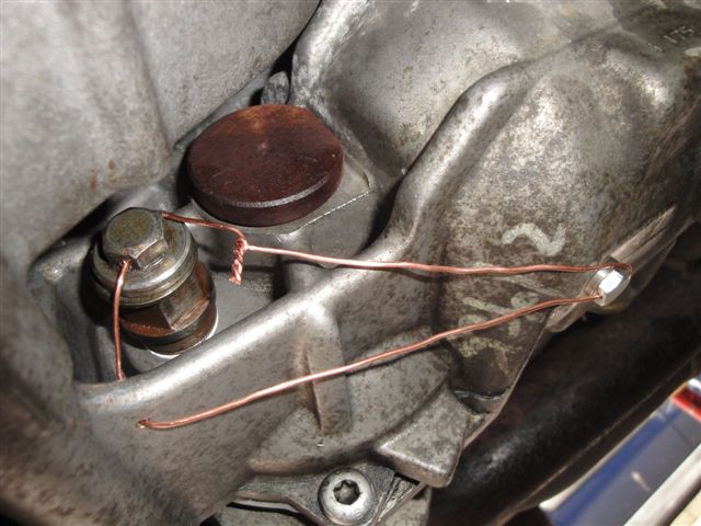
With the oil safely in and the end plug fitted, I've wired the two plugs and the casing together to make sure it stays there!
Job done and a definite step forward in improving both reliability and longevity of the notorious Transfer Box!!
Now, of course, the other thing everyone will want to know is how much oil was left in the box after the maximum drainage from the standard drain point had been achieved! Well, the answer is a staggering 250mls!! I repeat, 250mls. Which is probably why in JTIS, Jaguar state that to drain the box, the output pinion housing should be removed. Well, IMHO, I still think its removal is as likely to cause other problems when removing them for access. I'm happy with my alternative solution but leave it up to others as to how they address the situation.
Jaguar also state that the initial fill is 600 mls, but that refills should be 550mls to allow for imperfect drainage and that's when the pinion housing has been removed. I now drain through the new drain point and fill with 550 mls. If draining through the original point, then the residue of 250 mls means that only 300 mls need be added. With regular changes, this almost 50% change would probably satisfy many users and at least ensure that the correct level can be maintained.
First move was to jack the car up and put the front offside jacking point on an axle stand at a height of 16 inches. (This was done in the days before the idea of raising one side to empty and one to fill had become generally known!) The angle this puts the car at assists in effective draining of the oil and is high enough to get at everything necessary.
Now here's the first photo:
It shows my home made non return valve fitted instead of the original drain plug in place with its end plug fitted, ie my normal running configuration for the last two years. I'll come back to this valve later on, but I custom made it to suit the limited space available with an auto box.
The second photo shows the non return valve removed and the one year old, chocalate coloured 6000 mile oil draining. When all but the last few drips were collected, any remaining oil was left at the level of the bottom of drain orifice. I got about 200 mls out from here.
Now not many might wish to make the next move! I considered removing the pinion housing at the back of the 'box to enable the remainder of the oil to drain out, as is recommended in JTIS, but as this requires removal of the rear drive shaft and of course disturbing the transfer box pinion in its mesh with the countershaft, I felt this might create as many problems as it solved. So I spent a lot of time studying the 'box and checking its dimensions against published diagrams of its contents, finally deciding that there was a suitable position for a new drain point and that would be the most pragmatic answer. Before starting, I filed a flat surface (Not easy lying on your back!) that later would provide the land on which the new drain plug would seat and this photo shows the pilot hole of 3mm dia being drilled on the line of the output shaft, 47 mm away from the rear joint where the pinion housing attaches to the 'box. That exact position is important to avoid trying to drill into any of the box internals!
I accepted the risk of swarf ingress, judging that the oil draining as the drill broke through would flush the last bits straight out and noting that as the hole is above the drill, the vast majority falls away before breaking through. I still feel it was a worthwhile risk for me and, of course, no-one else is obliged to do it anyway!! Disclaimer still stands! As the drill broke through, I had the jug at the ready to collect the as yet unknown quantity of oil remaining below the level of the main drain plug.
When fully drained, measurements showed that the wall thickness of the 'box at this point was 7 mm and the pinion shaft was 27 mm from the outer surface, ie 20 mm clear of the inside surface. That's certainly not enough wall thickness to fit a standard 1/2 inch BSP/NPT, but does give sufficient meat for a decent length of a small diameter thread and plenty of room to allow the hole to be tapped right through. Some nervous tension was dissipating at this point!! After opening out the hole to 5 mm, this is the hole being tapped to a 6M x 1 thread. (I’d put the original plug back in temporarily, just to stop the inevitable dripping.)
I used plenty of grease on the tap to hold the swarf during this phase and removed the tap a couple of times to clean it during the process to limit transferring the swarf right through the hole. The alloy material tapped really smoothly and a good quality thread resulted. Nevertheless, if I hadn't tapped a good few holes in all sorts of materials before, I wouldn't have wanted this one to be my first!! There was only one shot at it unless I went up a size to try again!!
That completes the work necessary on the transfer box and now it's time to consider how to get some new oil back in and keep it there. This photo shows the constituent parts of the non return fill valve that I made a couple of years ago.
The body was turned up on a small lathe out of a scrap piece of mild steel bar, the valve seat was made of brass for no particular reason that I recall and is a tight tap-in fit to the body so it can be disassembled if required, the valve pintle utilised a modified chromed dome nut on a steel stem. The three flats on it just let it slide more easily in the body. The spring, from my come-in-handy box, very lightly presses the valve closed so it can be easily opened by the oil being pushed in. It doesn't have to be 100% tight in the non return operation. Just enough to stop the oil pouring out before the end plug is inserted.
The next photo shows the end plug, for positive sealing of the whole assembly on completion of an oil change that was made from an old sump plug, fitted with a bonded seal as shown and the filling connection, used temporarily instead of the end plug, when filling up.
This photo shows the non-return valve reassembled with PTFE tape added as a good, clean, effective sealing material and I have incorporated a 3 mm dia x 3mm cylindrical Neodymium magnet - very small but very strong for its size - in the end of the pintle. Also shown is the new M6 drain plug for the new drain point. It's a standard M6 hex head screw with a suitably dimensioned mild steel collar soft soldered to the back of the screw head to take a small O ring to provide the positive seal. It too has another of the magnets fitted in the end and peened over.
Just in case anyone asks, I'm sorry but I'm not in a postion to undertake making any of these valves or fittings for the aftermarket!
This photo shows the pressure filling system I now use as I need pressure to get past the non return valve. Those with manual boxes, able to fit an On/Off valve won't need this! Originally I just connected the oil bottle spout to the filling connection with a plastic tube and squeezed the bottle, having put only the requisite amount of oil in the bottle, but it was irritating and messy having to stop and undo the connection frequently to allow the bottle to re inflate! Jaguars deserve sophistication so I utilised a domestic detergent container (Did I say sophisticated!) with a connection point fitted through the cap and a non return valve through the bottom to allow connection to an electric tyre pump. With this lot connected up and the requisite amount of Castrol SAF - XJ (Now superseded by Castrol Syntrax LS 75W 140) in the bottle, a series of short runs of the pump (to avoid an exploding oil bomb!!) gets the oil in easily and quickly.
With the oil safely in and the end plug fitted, I've wired the two plugs and the casing together to make sure it stays there!
Job done and a definite step forward in improving both reliability and longevity of the notorious Transfer Box!!
Now, of course, the other thing everyone will want to know is how much oil was left in the box after the maximum drainage from the standard drain point had been achieved! Well, the answer is a staggering 250mls!! I repeat, 250mls. Which is probably why in JTIS, Jaguar state that to drain the box, the output pinion housing should be removed. Well, IMHO, I still think its removal is as likely to cause other problems when removing them for access. I'm happy with my alternative solution but leave it up to others as to how they address the situation.
Jaguar also state that the initial fill is 600 mls, but that refills should be 550mls to allow for imperfect drainage and that's when the pinion housing has been removed. I now drain through the new drain point and fill with 550 mls. If draining through the original point, then the residue of 250 mls means that only 300 mls need be added. With regular changes, this almost 50% change would probably satisfy many users and at least ensure that the correct level can be maintained.
#2
11-02-2013, 08:48 PM

#3
11-02-2013, 09:54 PM
Veteran Member
Join Date: Nov 2006
Location: Glasgow, Scotland UK
Posts: 47,303
Received 9,005 Likes
on
4,113 Posts
As asked in another thread, this is an account of how I added an additional drain point to my transfer gearbox plus how I refill it. But first a disclaimer! What follows is an account of what I have done to my own car to solve my own problems. What I have done is unlikely to be approved by Jaguar. Anyone who copies any of my actions or utilises any of the data does so entirely at their own risk and I cannot accept any responsibility for any problems or failures in any car arising from anyone copying my actions, or trying to do so.............
I'm going to edit the post to include the pics as larger and within the body for you.
I think this should be added as a "HOW TO" for those with issues relating that may want to attempt this.
Wouldn't surprise me if you got hounded for a DIY kit c/w write up instructions to sell on.
Excellent
The following users liked this post:
astromorg (11-03-2013)
#4
11-03-2013, 06:37 AM
I had considered doing much the same thing when my transfer case "prop shaft" bearings were removed.
I did not do it, thinking that I would eventually sell the car. I was also a bit concerned about cracking. As I had heard about some transfer case cracks.
I guess it's time to do it...
Thanks for the writeup!
I did not do it, thinking that I would eventually sell the car. I was also a bit concerned about cracking. As I had heard about some transfer case cracks.
I guess it's time to do it...
Thanks for the writeup!

#6
11-03-2013, 07:37 AM

I have done this and it is the only way to properly drain the TC. Good work Astromorg. I believe I was the earliest poster on the side drain and refill method and I had used it myself, but that method leaves 300 ml of the oil and sludge in the TC. Ford (Vistion) lied when they said the plug on the side is the drain, it's really not.
#7
11-03-2013, 08:39 AM
Well, the new plug is about the lowest point of the transmission - but it only adds 1/4 inch to what it was before! Furthermore, if you start catching the bottom of the transmission, you will by then have already removed the air cooler scoop for the transfer box and be about to do terminal damage to your exhaust system that is the lowest point of all!
Trending Topics
#10
09-30-2015, 02:10 PM
Senior Member
Very Good Work
I have a side question. As I looked at you photos I noticed a marking on your case. (436/2) My case is marked in the same spot with different numbers but in the same layout.
When I first saw mine I thunk it was a date the oil was changed, but it did not fit a date. Then I was thunk it must be a salvage yard marking, telling me my TC was replaced. I was very happy to see your marking as it must not be a salvage yard mark.
But what does it mean?
#11
09-30-2015, 04:10 PM
Sorry, I have no idea! But it's definitely been there since the car was new, when I bought it!
#12
09-30-2015, 08:07 PM
Veteran Member
I have done the same thing, but drilled a fill hole on top also. I didn't put it up, because I was afraid of being attacked for a little ingenuity. The whole idea of tipping the car almost over, to get a partial drain, and fill sounded like it bordered on insanity to me, and most folks here were doing it.......Thanks for coming out of the closet, making it easier for the rest of us thinking human beings. You should hear how I do a complete transmission flush on my XK8 trans. Why change 3 liters, when you can change all twelve. I flushed this trans close to the same way, with an electric pump.......Be cool....Mike
Last edited by mrplow58; 09-30-2015 at 08:14 PM.
The following users liked this post:
Jag4 (09-28-2016)
#14
02-07-2019, 08:31 PM


Veteran Member
#15
10-16-2019, 11:30 AM

Junior Member
Hi Guys, i met Astromorg on the UK Forums and he encouraged me to share my experience here too.
I did this mod a little over a week ago along with the TSB XT 308-01 for Output Seal Oil Leakage from the Transfer box.
Super nerve-wracking initially when you break through the casting but i can recommend it.
With the right amount of oil in, my X-Type feels noticeably smoother driving, day to day, i also had an unsettling 'road noise' that i put down to either diff or t/fer box (probably t/fer box given the pityfull amount of goo that came out after drilling).On a similar vein, whilst i had the tools out i also did a very similar mod to the Diff i can pm over pics if anyone has any interest. I may put a guide together at somepoint for that one, as not to hijack this thread.
if your not scared of a little modifcation, know how to handle a file, drill, M6x1 tap and have enough nouse not to strip a thread in cast aluminium then i urge you to do it. the piece of mind alone is worth every second of worry.
The following users liked this post:
astromorg (10-16-2019)
#16
11-30-2020, 02:44 PM
For those of us not as talented as Astromorg (Thank you BTW!) with turning small metal parts, this quick disconnect oil valve may do the job of draining and filling if it were tapped into the lowest point. It will protrude almost 7/8" with its cap on though, it's permanently in place. https://www.stahlbus-us.com/oil-drai...acing-cap.html
http://www.stahlbus.com/info/images/...glisch_web.pdf
For those with the room (don't recall if that's me, new X-type just 2 days ago) it may fit with an adapter in the original plug hole (The valve unit is UNF in varying sizes) and then just tap the lowest point and plug as above.
I think I'm going to give it a go. I'll post some pics if goes well and if it doesn't, well, you'll hear the scream.
Edit to add: I just emailed Stahlbus, they have a 1/2 NPT valve--no adapters needed.
Last edited by Anglofool; 11-30-2020 at 03:42 PM.
#17
12-01-2020, 01:42 PM

Thread
Thread Starter
Forum
Replies
Last Post
ancientsanskrit
X-Type ( X400 )
110
06-15-2019 12:46 PM
Dell Gailey
X-Type ( X400 )
3
04-29-2017 09:47 PM
Currently Active Users Viewing This Thread: 1 (0 members and 1 guests)