Which pot for manual headlamp leveling ?
#1
 05-22-2014, 09:23 AM

This thread is about
- Installing manual headlamp leveling in early X350s with automatic headlamp leveling and steel spring suspension conversion to get the german TÜV vehicle inspection sticker (UK?)
- Avoiding error messages after steel spring suspension conversion leaving the ASM connected
- Creating two headlamp leveling PWM signals for low beam and high beam
_________________________________________
Hi,
sooner or later the air suspension of my X350 will fight me down.
Unfortunately the german TÜV will not allow a conversion to steel springs without manual headlamp leveling. (That is not a joke)
Everything else to do is described by 34by151 here and below.
From VIN G39155 on, automatic headlamp leveling was omitted because the air suspension holds the chassis even anyway.
As my VIN is lower than G39155, headlamp leveling is included but without any manual control.
The headlamp leveling unit is controlled by the air suspension module through a single wire. Highly simplified it looks like:

The headlamp leveling units receive the signal:

If any of the knowledge holders of this wonderful forum has already experience with the usual single wire controlling (input/output triangles) or even has addressed the headlamp leveling units I would warmly appreciate his response!
I wonder what kind of potentiometer could be installed between CR89-3 of the ASM and ECS15 before the headlamp leveling units to lower the headlights ? (I hope lowering the voltage will result in lowering the headlamps)
Thanks
- Installing manual headlamp leveling in early X350s with automatic headlamp leveling and steel spring suspension conversion to get the german TÜV vehicle inspection sticker (UK?)
- Avoiding error messages after steel spring suspension conversion leaving the ASM connected
- Creating two headlamp leveling PWM signals for low beam and high beam
_________________________________________
Hi,
sooner or later the air suspension of my X350 will fight me down.
Unfortunately the german TÜV will not allow a conversion to steel springs without manual headlamp leveling. (That is not a joke)
Everything else to do is described by 34by151 here and below.
From VIN G39155 on, automatic headlamp leveling was omitted because the air suspension holds the chassis even anyway.
As my VIN is lower than G39155, headlamp leveling is included but without any manual control.
The headlamp leveling unit is controlled by the air suspension module through a single wire. Highly simplified it looks like:
The headlamp leveling units receive the signal:
If any of the knowledge holders of this wonderful forum has already experience with the usual single wire controlling (input/output triangles) or even has addressed the headlamp leveling units I would warmly appreciate his response!
I wonder what kind of potentiometer could be installed between CR89-3 of the ASM and ECS15 before the headlamp leveling units to lower the headlights ? (I hope lowering the voltage will result in lowering the headlamps)
Thanks
Last edited by LeoJagger; 05-28-2014 at 09:29 AM.
#2
05-22-2014, 03:57 PM

I suspect the signal is a PWM signal but you would nedd to put a cro on the line to work it out
MY XJR is vin G12xxx and does not have the leveling so that cant be correct
Headlamps do change height but this is to reaim the high/low beam as the hid lamps stay on for high beam
At the very least you could just unplug the servo motor inside the lamps but the beam reposition will not work
To get that working again you would need to measure the signal with a cro and replicate them. That should not be that hard to do
Cheers
34by151
#3
05-22-2014, 04:03 PM
Correction, the signal is PWM
To replicate all you need is a 555 timer
Google 555 timer
Cut the link from the air suspension and connect to the 555
Setup the 555 for 5v PWM output
Use 2 trimpots (switched) to vary the PWM signal to change the lamp height
Use the switch to change high/log beam position
Once you have it all setup replace the switch with a relay connected to the high beam to trigger an automatic change of PWM signal
If that does not make sense let me know and Ill give you more detail info on the 555 and connection
The 555 will cost you a few cents ant a electronics shop
Cheers
34by151
The following users liked this post:
LeoJagger (05-23-2014)
#4
05-23-2014, 06:50 AM
Hi 34by151,
having seen some of the circuit layouts of the 555, no doubt that design and buildup of a 555 controller is far to difficult for me, hence I would prefer to use a ready made module.
Would it be possible as well to use this or any other PWM controller ?
You told me to setup the 555 for 5v PWM output, does that mean that max output should be 41,67% of 12V input ?
To adjust that, may I use an analog measuring instrument ?

This controller is intended for small motors and LEDs.
Even the pot is included for 10.49$.
Its eBay item number is 290975934125.
Please use this direct Link.
Features :
(1) Working voltage: DC12V-DC32V
(2) Control power: 0.01-480W
(3) Quiescent Current: 0.02A (standby mode),
(4) PWM pulse width modulation range: 10%-95%;
(5) board size: 55mmX60mm
(6) PWM frequency: 13khz;
(7) High quality 50V1000uF electrolytic capacitors and electrolytic capacitors 50V330uF
If that one does not fit could you tell me why or recommend an alternative ?
Thanks
having seen some of the circuit layouts of the 555, no doubt that design and buildup of a 555 controller is far to difficult for me, hence I would prefer to use a ready made module.
Would it be possible as well to use this or any other PWM controller ?
You told me to setup the 555 for 5v PWM output, does that mean that max output should be 41,67% of 12V input ?
To adjust that, may I use an analog measuring instrument ?
This controller is intended for small motors and LEDs.
Even the pot is included for 10.49$.
Its eBay item number is 290975934125.
Please use this direct Link.
Features :
(1) Working voltage: DC12V-DC32V
(2) Control power: 0.01-480W
(3) Quiescent Current: 0.02A (standby mode),
(4) PWM pulse width modulation range: 10%-95%;
(5) board size: 55mmX60mm
(6) PWM frequency: 13khz;
(7) High quality 50V1000uF electrolytic capacitors and electrolytic capacitors 50V330uF
If that one does not fit could you tell me why or recommend an alternative ?
Thanks
#5
05-23-2014, 10:48 AM
For a module look for 555 servo
The frequency does not matter
When you connect the signal the lamps will move to the position of the signal
You can just turn the pot to position the lamp
So if you have 2 modules and feed both outputs to the headlamps via a relay
Trigger the relay from the high beam
Now you have one module sending a signal for high beam and the other for low beam
Adjust the high beam module then do the same for low beam
Here is what you need
2 X Servo Tester FOR ESC AND Servo RC | eBay
Remember also power the unit from 5V not 12V
If you need a 5V supply use a usb charger this is just a 5v power supply, cut off the usb plug and connect to the bat input of the servo tester
Cheers
34by151
Last edited by 34by151; 05-23-2014 at 10:50 AM.
#6
05-26-2014, 05:20 AM
Hi 34by151,
please check if I got all that right.
This is the Servo Tester that should fit:

There are cheaper ones, but this one has got a nice knob and starts up in manual mode, which is convenient for dashboard integration.
Let us hope that the german TÜV accepts the knob.
Here is an Auto charger unit, it is a DC-DC step down converter from 12V to 5V without connector jacks.

Please search for actual items with common ground, for example eBay item 181379138632:
There are modules without case as well, that obviously provide common ground:

Features: Brand new and high quality.
This HRD converter is a voltage switching regulator providing capable of driving a 3A load with good performance and economic DCDC convertor.
It is using HRD module with minimum components to provide fixture DC output 5V.
2x capacitors 220uF 63v & 470uF 25v to provide guard noise filter at input and output and power indicator LED.
It can be become adjustable converter if add a variable resistor.
Input voltage: Wide range of input 12-50v.
Output Voltage: 5V.
Output current: Rated current 3A.
Conversion efficiency: Up to 80%.
Input Capacitance : 50v330uf.
Output Capacitance: 16v1000uf.
Operating temperature: Industrial grade (-40 ? to +85 ?).
Full load temperature rise: 40 ?.
Connection mode: Jack with screw fix.
Specifications:
Original box: no
Color:As shown in the picture
Item size: 53 x 47 x 29mm
Net weight: 46g
Package weight: 55g
_______________________________
As to be seen in the video, it is sufficient to connect the 3 Pins of CH1 to get the servo tester to work.
The upmost pin has to be connected to ECS15, so that the outcoming yellow cable CR89-3 of the air suspension module behind the backseat is left without connection.

The middle Pin of CH1 has to be connected to +5V output of the Auto charger unit.
The lowest Pin of CH1 has to be connected to -5V output of the Auto charger unit, which has to be connected to ground (chassis) as well.
I hope it will not cause any problem to connect -5V output of the charger unit to ground, because the -12V input of the charger unit will be connected to ground too.
The +12V input of the charger unit has to be connected to Ignition or SSP (Switched System Power), for instance to the connector CR-88-2 of the ASM, which is connected to CR81-2 of the rear power distribution fuse box (98).
As this connection contains a fuse (F12) of 10A and the charger unit produces just 15W or 25W max output, a cable fuse of 1A or 2A should be used here.
The ASM CR-88-2 must stay connected to CR81-2 of the rear power distribution fuse box (98), otherwise the ASM will not start up.
To emulate electric resistance values at the four or five sensor inputs, 8 to 10 resistors are needed.
The method to determine the their values is explained here and below by 34by151.
This procedure has to be performed BEFORE the conversion, particularly BEFORE the removal of the height sensors.
Remember the car has to be parked on a flat surface before you start with that.
All resistors might have different values.
Two of them are needed to emulate the pressure sensor of the Air Suspension Valve Block:

They have to be fixed between the ASM connectors CR90-13 and CR90-14 and between CR90-14 and CR90-15.
The remaining resistors are used to emulate the height sensors.

They have to be fixed between these ASM connectors:
LF CR90-1 - CR90-2
LF CR90-2 - CR90-3
RF CR90-4 - CR90-5
RF CR90-5 - CR90-6
Both RF resistors are needed only in X350s built before Dec. 2003.
RR CR90-7 - CR90-8
RR CR90-8 - CR90-9
LR CR90-10 - CR90-11
LR CR90-11 - CR90-12
I would appreciate if you could check all that.
With compliments to the Arnott engineers.
I wonder if they could provide a ready made CR90 connector for the ASM?
Thanks
please check if I got all that right.
This is the Servo Tester that should fit:
There are cheaper ones, but this one has got a nice knob and starts up in manual mode, which is convenient for dashboard integration.
Let us hope that the german TÜV accepts the knob.
Here is an Auto charger unit, it is a DC-DC step down converter from 12V to 5V without connector jacks.
Please search for actual items with common ground, for example eBay item 181379138632:
- The DC Converter used in automotive, posts and telecommunications, communications, electricity, coal, aerospace, defense, surveillance systems, railway signals, medical equipment, instruments and meters, LED displays, cable TV,GPS,MP3, MP4 and other fields.
- Fully protection: over/under voltage input, overload, overheat and short circuit
- This module have been used in many fields, such as: Industrial Control System, Power system, Apparatus and Instrument, Medical facilities,
- Rail-transit system, Telecommunication Equipment, Security and Protection Equipment, Military Industrial System etc.
- Input voltage: DC 12V/24V (Vin range: DC 9~35V)
- Output voltage: DC 5V
- Output current: Max: 5A
- Output Power :25Watt
- Efficiency: up to 90%
- Wire lenght: 150mm
- Potting: Epoxy Sealed
- Dimension: 46 x 35 x 16 (mm)
- Weight: 80g
There are modules without case as well, that obviously provide common ground:
Features: Brand new and high quality.
This HRD converter is a voltage switching regulator providing capable of driving a 3A load with good performance and economic DCDC convertor.
It is using HRD module with minimum components to provide fixture DC output 5V.
2x capacitors 220uF 63v & 470uF 25v to provide guard noise filter at input and output and power indicator LED.
It can be become adjustable converter if add a variable resistor.
Input voltage: Wide range of input 12-50v.
Output Voltage: 5V.
Output current: Rated current 3A.
Conversion efficiency: Up to 80%.
Input Capacitance : 50v330uf.
Output Capacitance: 16v1000uf.
Operating temperature: Industrial grade (-40 ? to +85 ?).
Full load temperature rise: 40 ?.
Connection mode: Jack with screw fix.
Specifications:
Original box: no
Color:As shown in the picture
Item size: 53 x 47 x 29mm
Net weight: 46g
Package weight: 55g
_______________________________
As to be seen in the video, it is sufficient to connect the 3 Pins of CH1 to get the servo tester to work.
The upmost pin has to be connected to ECS15, so that the outcoming yellow cable CR89-3 of the air suspension module behind the backseat is left without connection.
The middle Pin of CH1 has to be connected to +5V output of the Auto charger unit.
The lowest Pin of CH1 has to be connected to -5V output of the Auto charger unit, which has to be connected to ground (chassis) as well.
I hope it will not cause any problem to connect -5V output of the charger unit to ground, because the -12V input of the charger unit will be connected to ground too.
The +12V input of the charger unit has to be connected to Ignition or SSP (Switched System Power), for instance to the connector CR-88-2 of the ASM, which is connected to CR81-2 of the rear power distribution fuse box (98).
As this connection contains a fuse (F12) of 10A and the charger unit produces just 15W or 25W max output, a cable fuse of 1A or 2A should be used here.
The ASM CR-88-2 must stay connected to CR81-2 of the rear power distribution fuse box (98), otherwise the ASM will not start up.
To emulate electric resistance values at the four or five sensor inputs, 8 to 10 resistors are needed.
The method to determine the their values is explained here and below by 34by151.
This procedure has to be performed BEFORE the conversion, particularly BEFORE the removal of the height sensors.
Remember the car has to be parked on a flat surface before you start with that.
All resistors might have different values.
Two of them are needed to emulate the pressure sensor of the Air Suspension Valve Block:
They have to be fixed between the ASM connectors CR90-13 and CR90-14 and between CR90-14 and CR90-15.
The remaining resistors are used to emulate the height sensors.
They have to be fixed between these ASM connectors:
LF CR90-1 - CR90-2
LF CR90-2 - CR90-3
RF CR90-4 - CR90-5
RF CR90-5 - CR90-6
Both RF resistors are needed only in X350s built before Dec. 2003.
RR CR90-7 - CR90-8
RR CR90-8 - CR90-9
LR CR90-10 - CR90-11
LR CR90-11 - CR90-12
I would appreciate if you could check all that.
With compliments to the Arnott engineers.
I wonder if they could provide a ready made CR90 connector for the ASM?
Thanks
Last edited by LeoJagger; 06-02-2014 at 01:53 AM.
#7
05-26-2014, 06:37 AM
Spot on the first servo tester is perfect
Lets deal with the headlamp leveler first
If you look at the circuit diagram you will see the headlamp is actually a stepper motor and a controller. The rotation of the motor being controlled by a PWM pwm signal
So what is the difference between a stepper motor and servo motor, not much. A servo is just a stepper with position feedback
Ill explain that in term of the headlamp
The PWM signal is fed to the Headlamp Level Module
This decoded the percentage the sign is on or off and applies power to the motor to turn to the position. Lets say 0% is all the way down and 100% is all the way up
There is no feedback in this (stepper design) so the actual position is never known and my be off over time
In servo like in a radio control one you also have a pot or variable resistor on the shaft that turns with the motor shaft. This provides a feedback. So rather than just "steeping" forward or back it moved in a direction till the resistor feedback equals the "commanded" position as dictated by the PWM signal
The point being either way the PWM signal is the same
So all you need to do is cut the line going to the headlamp and feed in your own pwm signal. The logical place is at the ASM as the signal then goes to both headlamps but the easiest will probably be at EC1-9 or ECS15 (see the diagram in your first post)
To get the 5v just get a 7805 voltage regulator

Connect as in the pic the output is 5V
So input is +12, output is +5 and ground is well ground
Now you also need to have hi beam and low beam alignment
So you need 2 PWM signals or 2 of this modules
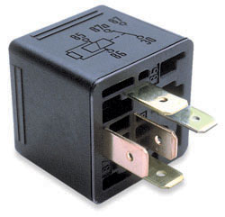
You need a DPST relay like this

Connect
Pin 85 to ground
Pin 86 to the high beam (EC6-7)
Pin 30 to PWM signal wire going to the headlamps
Pin 87A to the first servo tester output
Pin 87 to the second servo tester output
The fist servo test will give you the low beam position and the second the high beam position
You can just turn the pot to adjust the height on low beam then switch to high beam and do the same
Once your done put a dob of sealant on the knob to stop it moving
Cheers
34by151
Lets deal with the headlamp leveler first
If you look at the circuit diagram you will see the headlamp is actually a stepper motor and a controller. The rotation of the motor being controlled by a PWM pwm signal
So what is the difference between a stepper motor and servo motor, not much. A servo is just a stepper with position feedback
Ill explain that in term of the headlamp
The PWM signal is fed to the Headlamp Level Module
This decoded the percentage the sign is on or off and applies power to the motor to turn to the position. Lets say 0% is all the way down and 100% is all the way up
There is no feedback in this (stepper design) so the actual position is never known and my be off over time
In servo like in a radio control one you also have a pot or variable resistor on the shaft that turns with the motor shaft. This provides a feedback. So rather than just "steeping" forward or back it moved in a direction till the resistor feedback equals the "commanded" position as dictated by the PWM signal
The point being either way the PWM signal is the same
So all you need to do is cut the line going to the headlamp and feed in your own pwm signal. The logical place is at the ASM as the signal then goes to both headlamps but the easiest will probably be at EC1-9 or ECS15 (see the diagram in your first post)
To get the 5v just get a 7805 voltage regulator
Connect as in the pic the output is 5V
So input is +12, output is +5 and ground is well ground
Now you also need to have hi beam and low beam alignment
So you need 2 PWM signals or 2 of this modules
You need a DPST relay like this
Connect
Pin 85 to ground
Pin 86 to the high beam (EC6-7)
Pin 30 to PWM signal wire going to the headlamps
Pin 87A to the first servo tester output
Pin 87 to the second servo tester output
The fist servo test will give you the low beam position and the second the high beam position
You can just turn the pot to adjust the height on low beam then switch to high beam and do the same
Once your done put a dob of sealant on the knob to stop it moving
Cheers
34by151
Trending Topics
#8
05-26-2014, 07:15 AM
Ok so lets deal with the ASM now and how it manages the airbag and the vehicle height
You may need to go back and reread what I just wrote about steppers and servos
Put simply the air suspension is just 4 servo's!!!
If you think of one wheel the motor is the air bag and the position feedback is the height sensor
So the ASM is really just a 4 channel servo controller
The airbag itself has no feedback so with it is not that reverent when disconnected. No the ASM may be smart enough to measure the resistance of the solenoid and generate a fault with a disconnected solenoid. If it does you just need to measure the resistance of the solenoid and put a resistor in place of each one. Remember here we are talking about the solenoid not the airbag. You can leave the solenoids connected
the height sensors are the relevant parts you need to emulate. here you need to know 2 things so lets use the LH front sensor to work this out
1. Measure the resistance on Pins EC45-5 and EC45-1. This is the value of the pot you need
2. The Resistance between Pins EC24-5 and EC45-4 this represents the height of the wheel
So next you need to do some more reading. Read Cambo's thread on how to lower the XJ
This is where the ASM is programmed for the "Normal Ride Height"
In other words the ASM commands the the solenoids to add or subtract air till the feedback from the height sensor matches the value stored in the ASM for that wheel
So how this applies to you
You need to fool the ASM to thinking it is at the programmed ride height for each wheel. Lets asume you have connected the pot in place of the LH front height sensor. Using SDD turn the pot till you get the SDD reading the normal height value. Now the ASM thinks it always at the programmed height.
Now all you need to do is repeat for the other 3 wheel sensors
There is another feedback in the ASM for the compressor
This is the pressure sensor. Again we emulate it in the same way
Measure the resistance of pins CR92-1 and CR92-3, this is the value of the pot you need. Connect a pot to with the outer pins to CR92-1 and CR92-3, connect the center pin on the pot to CR92-2
No turning the pot will tell the ASM is the pressure is low or high
To work this out we need a pair of multimeters or a pir of globes on the air compressor plug.
Connect a connect a globe or multimeter to pins EC62-1 and EC62-2 (the vent solenoid) and to pin EC60-2 and ground (compressor)
Turn on the ignition. and turn the pot till neither have power.
IE if the ASM think the pressure is high it will activate the vent and if it is low it will activate the compressor. If neither is on it just right
Do you see a repeating theme here goldy locks!!!
You don't need to worry about the Damper actuator, its an output anyway that controls the shock stiffness. The ASM does not care if its disconnected.
As for the rest of the CAR's modes all it cares about is the ASM is talking on the bus and not sending out faults to the instrument cluster.
So now we have fooled the Height sensors and the Air pressure sensor the ASM just needs to have the accelerometers sill connected to not send out errors.
If you want I can explain what these do but you don't need that to eliminate the error on your coil conversion
Cheers
34by151
#9
05-28-2014, 01:13 AM
______________________
-5 and -1 on each wheel sensor is the pot value
-4 is the output which is proportional fom 0 to max
The wheel sensors are on EC45, EC18, CV3 & CV4 so EC24 was typo, sorry.
A battery disconnect should (but not sure) reset the suspension alert but it will not change the programming.
Most alerts are timed or require 2 or more drive cycles to come up on the dashboard.
At the end of the day the "normal" height for each wheel is stored in the ASM.
You can change this value in SDD.
So the ASM is going to attempt to raise or lower the airbag to get the stored value to equal the value from the wheel sensor. If you dont have that or compressor pressure you will get an alert.
Fake those 2 and no alerts!

Thread
Thread Starter
Forum
Replies
Last Post
aholbro1
XJ XJ6 / XJR6 ( X300 )
17
08-05-2021 05:02 AM
rentzoo
S-Type / S type R Supercharged V8 ( X200 )
11
11-10-2015 04:56 PM
Currently Active Users Viewing This Thread: 1 (0 members and 1 guests)