When you click on links to various merchants on this site and make a purchase, this can result in this site earning a commission. Affiliate programs and affiliations include, but are not limited to, the eBay Partner Network.
I have just put the XJR engine into the engine bay for hopefully the last time. The gearbox is currently being held up by some wooden blocks for now. I am looking into the electronics first. Currently I can get the ECU to talk to the ODB2 interface so I am working through the various problems I come across. The through bulkhead plug/socket gave me a few issues but I have resolved those now. I connected up the XJR display to see what else was going on. The digital display shows the mileage (which is why I need the display working) but also flashed up AIRBAG and FLUID. I grounded the appropriate brake fluid wire and the FLUID message stopped. I now need to work out how to stop the AIRBAG signal. Grounding the appropriate wire does not seem to work. I think I may have damaged one of the chips (HC151) on the display board so I have ordered a new one.
Been doing a little work to the car. I worked out the correct signals required to get rid of the airbag fault. Still not decided if I will use the Airbag module and some resistors or just generate the signal using something else. I am still getting error P1621 which is imobiliser error. I have checked through power, ground connections and various other signals between the modules but it still will not engage the starter. I am looking at the original key switch assembly at the moment. You have to use relays to change the +B signals from the key positions on the Series 2 to switching to ground for the various control modules. I need to introduce a slight delay in the relays to keep them engaged because the key switch looses connection for a split second between positions. This will cause the relays to click and the modules to reset so could be the cause of multiple issues.
The easy way is to change the ECU! Andy Stoddart ( XJR Engineer) on here can do that, or buy a North American spec ECU, those don't have the imoblizer. You could use the Series II starting circuit. Makes life easier!
Dodgey, The circuit that you are chasing down works kind of like this, the key/ exciter/ring sends a signal to the body processer module which sends a signal to the ECM which sends a signal back to the BPM to operate the starter. The ignition switch plays into this by providing various grounds at various sequences to match what the BPM and the
ECM want to see. Would you like a factory schematic of the starting system?
Larry Louton send mailing address.
Thanks for the offer of some extra info. I do have copies of the X300 electrical guide but if there is more detail available then please forward to me. There are a lot of documents here on the forum too. As I started with a complete XJR I do have the various Modules etc. In my setup, the ignition ring sensor is connected to the Exciter box and subsequently to the Security & control module. The actual XJR key was sitting inside the ring sensor during my tests. I did notice that there is a "key in" signal which should be grounded so I tried that during the last tests.
I could of course do something like, "Use the S2 key switch for the S2 electrics and place the XJR key assembly somewhere in the car to act as the engine stop/start system" but I would rather not.
My next step is to connect up lots of LED's to monitor the status of all of the various signals that I think are related to the issue and debug from there.
Jagboi64: Yes the North American ECU or XJR engineers reprogram are both good options along with a stand alone programmable ECU. The challenge here is that it should work with the set up I have. I need to spend some time trying to resolve it prior to taking a second option. I convinced myself it would work and that I could do it so I will have to give it a little more effort for now. It would also take a lot of work to undo all that I have installed into the car already.
I know what you mean about the loom! That's about the stage I am at with my project, just have the wires that run through the front wings to strip out. I'm just glad mine doesn't have the imobiliser, makes the wiring a bit simpler and one less module I need. I'm just putting in the ECU and TCM in my Daimler.
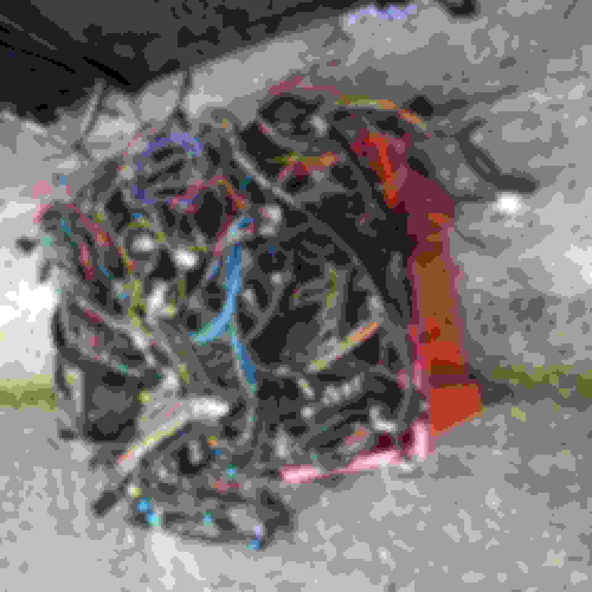
To be fair the picture above is all of the loom from an XJR. I am using the ECU, Transmission ECU, Body & control module, the instrument display PCB and the Security module. It looks like the image below at the moment. A lot of tidying up once it is working.
current state! the wires going to the left out of the door are not used so will be removed when it finally works.
I'll be curious about what you do with the speedometer and tach. Are you using the XJ Series II instruments, or adapting the X300 display somehow? Do you plan to keep the trip computer? I want to do that, but not sure how I'll make it work, or where I will mount the computer.
The plan, which will no doubt change, is as follows:
I already have the milometer display up and running. For the speedo, the feed will have to come from the output speed signal from the gearbox. It is approximately 15 x too fast. You can divide by 16 really easily with a single chip so thats the starting point. That will feed the original PCB that is behind instrument assembly. Once I have that signal sorted it is just a matter of driving the gauge itself. Hopefully I can then add a little bit of trim to the circuit to make up for the difference between 15x and 16x at the actual gauge. The gauges in the XJR are all just small "motor looking devices" driven via 3 wires each. I have tried a quick test fit into a spare S2 gauge and it does fit quite well. I do need a little more fettling to get it to fit better but the picture below shows how it can fit inside the original assembly.
You then need to sort out the odometer part of the original S2 gauge as you cant use the mechanical one. I took a photo of the dial with the odometer in place. I then printed it out and stuck it in place behind the display. With the glass lens in front you could not tell the difference. I do have the XJR digital odometer display working and it is easy to remove from the XJR display as a single unit. That means I can mount it somewhere in/around the dash but the location is yet to be decided. The original S2 dash needs refurbishing as it is badly cracked and faded in places. I have a spare so I might try inserting the digital display somewhere discretely into the wood dash itself.
There was a previous post that mentions the S3 gauges are electronic rather than manual so that might be an easier way to get the speedo working. I might try that out if I can find one in the garage. I plan to use a mixture of the original S2 gauges and the XJR ones but it will be a much tighter fit to get the XJR gauges into the smaller S2 gauge cases. It might be better to try to drive the old gauges from the XJR display PCB instead.
What I was planning to do for odometer on mine was use the SIII speedometer I already have, and drive it through the output shaft speed sensor of the transmission. As you pointed out, that's too fast, but there is an adapter box for that purpose: Universal Speedometer Signal Interface
The transmission shaft puts out 115,000 pulses per mile, while a Series III speedometer (and trip computer for that matter) wants to see 8,000. Interestingly, on the XJR where the speed signal is generated by the ABS system, the input to the speedometer is 7200 pulses per mile.
If I use the XJR trip computer, I might have to use 2 of the Dakota Digital boxes, one for the speedometer, and one for the trip computer.
According to the electronic guide for the XJR the trip computer is part of the Instrument display board. It has the speed signal input from the ABS module (FC9-15) and there are three switches for the trip settings plus a reset button. There is just one "speed" signal require to drive the trip computer. I would expect you could send the same speed signal to the speedometer as well.
I did not drive the XJR I started with so I am assuming the trip "details" appear in the small digital odometer inside the instrument display? I did wonder if I should just add the switches somewhere to enable that feature too.
As I mentioned the signal is ~16 times too fast. The numbers you gave (115,000/7200) are 15.972 times too fast. If we divide by 16 we will be pretty close. How do you do that? See the digital divider section in wikipedia
quote/
For power-of-2 integer division, a simple binary counter can be used, clocked by the input signal. The least-significant output bit alternates at 1/2 the rate of the input clock, the next bit at 1/4 the rate, the third bit at 1/8 the rate, etc. An arrangement of flipflops is a classic method for integer-n division. The easiest configuration is a series where each flip-flop is a divide-by-2. For a series of three of these, such system would be a divide-by-8. By adding additional logic gates to the chain of flip flops, other division ratios can be obtained.
/quote
E.g. add another logic gate and you divide by 16. If you do have some electronic skills then I found a really clear example for a divide by two circuit here (It has extra component to generate the input and LEDs etc so it is simpler than it looks) I have yet to do this as I need to get the engine running first. Then I will be able to see the signal generated by the transmission and test it out.
Back to diagnosing the immobliser issue for now...
I did not drive the XJR I started with so I am assuming the trip "details" appear in the small digital odometer inside the instrument display?
Yes, the trip computer display is in the odometer space. Pressing the end of the turn signal stalk cycles through the information.
I liked the Dakota Digital box because it is adjustable. You can drive on a level road on cruise control with a separate GPS device displaying true road speed and press the up or down buttons on the Dakota Digital box to bring the speedometer needle to match the true road speed. It's easy to compensate for different tire sizes or rear axle ratios that way.
I'm thinking of doing something similar
I have 3 MK2 shells in various stages of disassembly and rust (purchased that way)
and I have found a '96 xj with lower mileage with a bad impact the back end.
Hoping that starting with a running car means I dont have the same issues you're dealing with.
Hoping that starting with a running car means I don't have the same issues you're dealing with.
Mark 2's are more difficult just because the space in the engine bay is so tight. Make sure you have a copy of the XJ6 Electrical Manual and understand it well. You'll have to fake some of the ECU inputs for things like traction control and ABS to make the ECU think they are there, but turned off.
As far as using the GPS for speed all you need is a GPS unit, even a hand held. I use one to calibrate my speedo in an older car. As to how you drive the instrument? Well...i'm not even sure the rally guys do that. That would be cool though.
Well... I guess I wasn't much help. But it sure sounds like fun.
It's an interesting idea to use a GPS to drive the speedo and doable. In fact if the instruments are electronic then a small computer board like a Raspberry PI with an IP board could do it. It would read the GPS signal and determine speed and output the appropriate voltage or pulse rate or whatever. Computers are very good at converting from one unit of measurement to another.
If this sort of thing is interesting to people then I would be interested in developing this idea.
I now get the Body Processor and the Security Module to agree and it turns the engine over from the key. No shortcuts, no cheating, the security imobiliser is in the circuit and drives the original XJR starter relay which engages the starter motor and then turn the engine over. I have yet to check if the fuel inhibit is ok but it should be considering all the checks in place to stop you even turning the engine over.
A long, long way to go yet but very, very happy right now!
The last missing signal was actually a switch position 2 ground signal to the body processor. It is in the circuit diagram for the lighting, I assume it was for changing the lights between sidelights and headlights when ignition was on. I was basically going through every circuit diagram and checking which signals could possibly be required to start the car and came across this one. Figure 9.10 BCM connector FC pin 31. It is switched to ground when the key is in position 2 (8 II). I used the same signal from a relay that uses the original S2 ignition switch position 2 +B signal. It switches to ground driven by the ignition switch. I send that ground signal to the two fuse box relays & few other places. I don't know why it is needed but at the moment I don't care either!
switched ground signal required at FC2-31
Have a great weekend, I am ;-)
Dodgy.
Last edited by dodgy; 09-11-2016 at 06:13 AM.
Reason: Picture would not load
I ended up using two Dakota digital units to operate the original tach and speedo head for my Series three. little head scratching went on about the speedo interface adjustment for speedo accuracy but the tach dropped right in and worked with no adjustment whatsoever.
Larry Louton
I have done a slightly similar conversion to a 1985 XJS that had a 3.6L AJ6 motor in it with the old style P series EFI and the 5 speed Getrag manual gearbox. When I first got the car it did not run at all on the original P-series injection. So I scrounged all of the EFI parts from the 1988 - 1989 XJ6 cars at various local junkyards and converted the car to use the newer engine management from those early XJ40 cars with the original 3.6L AJ6 engine. This worked fine for a couple of years but then the original 3.6L engine got so worn out that one day it refused to start. Turns out most of the rings and pistons had serious damage and the compression in the motor dropped so low that the engine would no longer start.
At that time I had a spare low mileage 4.0L AJ16 motor lying about so I decided to slot that into the car. I did this back in 2012 so I recall swapping over the 3.6L motor mounts and obviously bolting up the manual flywheel. I used the 3.6L crank pulley with the trigger wheel pattern for the 3.6L ignition system. I stuck with the whole intake manifold setup from the 3.6L as well. I also recall swapping over the power steering pump assembly from the engine 3.6L as well so I could stick with the same power steering hose setup from the XJS. The only other major thing I recall was having to redrill some holes on the exhaust side of the AJ16 cylinder head to match the holes in the 3.6L exhaust manifolds. The blank bosses were still in the AJ16 to match up with the 3.6L exhaust manifolds so that was not that big of an issue.
So now I have a 1985 XJS with the 4.0L AJ16 motor in it. Andy tells me my ignition timing is probably quite retarded though so I am contemplating switching the whole thing to a megasquirt systems so I would have programmable control over the ignition timing map. Since I have prior experience with using a Meagsquirt system on my 1974 Jensen Healey, this seems like a possible solution.

 06-28-2016, 04:22 PM