1992 Jaguar XJ6 not getting fuel to engine
#1
 01-28-2009, 11:09 AM


Good morning. This is my first post as I just registered bout 2 minutes ago. I purchased a 1992 XJ6 Sovereign with 95K original miles on Monday from an elderly gentleman who took real good care of it both cosmetically and mechanically.
Here's the problem; The car was running fine with no indicatin that there wee any issues. He parked it one day and when he went out the next day it wouldn't start.
He was told it was the fuel pump. So he had a mobile mechanic install a brand new fuel pump that he purchased from a dealer. Still the car wouldn't start.
Well after it has been sitting for many months he decided just to sell it and I bought it and had it towed to my house.
I can hear the fuel pump kick on and run when I turn the ignition. But if you disconnect the fuel hose in the engine bay from the fuel rail it is bone dry and no fuel is getting from the tank through the fuel lines to the engine.
Here's what I've done so far;
1. Replaced every fuse in the car
2. Made sure the inertia switch was not tripped. This is the switch on the driver side kick panel close to the firewall in the passenger
compartment.
3. Added gas to the gas tank
4. Installed new battery
I've read it could be the ignition switch, distributor, solenoid, but all of these appear to be working properly.
What I haven't done is disconnect the fuel line where it comes out of the tank or fuel pump to see if it's actually pushing fuel. I think I need to do this and then depending on results move to the next connection (fuel filter) and see if I have fuel going in and coming out of the filter and then depending on results keeping moving forward until I find the problem.
My question is; Am I going about this the right way or is there something I've said that makes one of my fellow enthusiast go; "Oh that's a classic symptom of XXXXX problem"
Are there any other switches that may have tripped on gone bad that my symptoms indicate I should check or replace?
Thanks in advance for your help!
Jeff
The following users liked this post:
Rex L Harrisen (04-30-2015)
#2
01-28-2009, 11:23 AM

Join Date: Mar 2008
Location: Powell, Ohio U.S.A. 43065
Posts: 2,521
Likes: 0
Received 70 Likes
on
56 Posts
Greetings,
You are on the right path. Since you can hear the pump running, either the pump is defective or improperly installed in its module, or the fuel line is blocked between the fuel tank outlet and the fuel rail in the engine bay. Disconnecting the inlet pipe at the fuel filter is the next place to look.
You are on the right path. Since you can hear the pump running, either the pump is defective or improperly installed in its module, or the fuel line is blocked between the fuel tank outlet and the fuel rail in the engine bay. Disconnecting the inlet pipe at the fuel filter is the next place to look.
#3
01-28-2009, 11:27 AM
Thanks for the quick response. I have 2 followup questions.
1. Is there a guide for properly installing the fuel pump online somewhere?
2. Can you recommend a repair or shop manual to get for this car?
I usually try to do all of my own work if at all possible and I know having the right manual is always a huge plus.
Thanks
1. Is there a guide for properly installing the fuel pump online somewhere?
2. Can you recommend a repair or shop manual to get for this car?
I usually try to do all of my own work if at all possible and I know having the right manual is always a huge plus.
Thanks
#4
01-28-2009, 11:42 AM
Senior Member
I know haynes makes an xj40 manual, but also, there is a relay that controls the ignition coil, fuel pump, and injectors, and while power may be getting to your pump, it's not allowing it to realize that it needs to get fuel moving. the stock one is white, I can't remember where it is, but it controls a very large chunk of components ignition wise minus the starter. When that relay goes bad, it'll crank and crank all day long to no avail. I'd try to identify which relay it is, and switch around a few and see if that doesn't make it come alive. Most of the time it's just a cold break inside that particular relay. If you can't identify it, just shoot from the hip and switch a bunch of them with the same wiring diagrams written on the side.
cheers,
pancho
cheers,
pancho
The following users liked this post:
Rex L Harrisen (04-30-2015)
#5
01-28-2009, 11:50 AM
Join Date: Mar 2008
Location: Powell, Ohio U.S.A. 43065
Posts: 2,521
Likes: 0
Received 70 Likes
on
56 Posts
The paper manual set from Jaguar for your XJ6 was an expensive five volume set of notebooks. All of this information is obtainable on CD, if you browse eBay you will find one. Haynes publishes a manual that will help with many minor repair and maintenance items. I think I have a used one if you are interested.
I'm not certain of where to direct you for specific fuel pump module assembly instructions. Perhaps hold off until you are sure this is necessary: in that event, you will have to remove the tank to pull out the module, and I could probably talk you through it from there if all else fails.
When the ignition is turned on, power through the fuel pump relay makes the pump run for about two seconds. That indication means the inertia (cutoff) switch and pump relay are working. Cranking the engine will allow the pump to resume running. A normal pump does not move a tremendous amount of fuel, but you should still get a decent stream of maybe 4-6 oz. of fuel in the two seconds.
The following users liked this post:
Rex L Harrisen (04-30-2015)
#6
01-28-2009, 12:31 PM
Hi Woodpuppy,
Got this rather long-winded missive off the Jag-Lovers.org site. Hope this helps without numbing your mind too much. Any inaccuracies will be picked up by the keen-eyed techs who grace these forums.
Mike
Fuel system ( ,)
[align=right]Back to Book Index [/align]11.1 - Collapsing Fuel Tank Warning ( ,)
The injection pumps used on these cars has enough power to suck the tank in on itself in the event of a venting problem.
There are the more usual vent problems caused by stuffed check valve, carbon canister, or such. There is also the vent line under the car which can be plugged solid with dried out fuel. What appears to happen is the owners fill the car to the top of the neck, which puts the fuel level above the fuel separator in the vent system. So raw fuel runs in to the vent line and evaporates leaving the sludge behind.
[align=right]Back to Book Index [/align]11.2 - Overview of the Fuel Injection System ( ,) There are the more usual vent problems caused by stuffed check valve, carbon canister, or such. There is also the vent line under the car which can be plugged solid with dried out fuel. What appears to happen is the owners fill the car to the top of the neck, which puts the fuel level above the fuel separator in the vent system. So raw fuel runs in to the vent line and evaporates leaving the sludge behind.
The engine management system is controlled by the ECU and maintains optimum engine performance by metering the fuel into each cylinder's inlet tract and adjusting the ignition timing angle at the sparking plugs. It correlates data received from a number of sensors located on and around the engine to provide optimum ignition timing and fuel metering parameters relative to engine load and speed. The EM system also controls three features which may have a direct bearing on starting problems:-
1 Fuel pump - to prevent fuel flooding and/or spillage when the engine is stationary with the ignition switch in position 'II'.
2 Cold start control - to ensure there is sufficient fuel in the inlet manifold to create a combustible air/fuel mixture.
3 Idle speed control - to compensate for varying engine temperature and load conditions.
The system also incorporates a 'limp home" facility allowing continued engine operation following certain sensor failures, the specific failure being indicated on the instrument pack.
Fuel is delivered to solenoid operated injectors by the pump operating (via a variable pressure regulator) at virtually constant pressure so that the quantity of fuel injected for a given duration of injector ‘on’ (open) time is constant.
Injector operation is by means of an electrical pulse which actuates a solenoid valve in the injector body. The duration of the pulse is determined by the ECU on intake air and engine speed information from the FLOWMETER and CRANKSHAFT SPEED SENSOR.
Correction factors are applied by the ECU to provide two functions which may cause starting problems:-
1 - Cranking enrichment during starting.
2 - Temperature enrichment during starting and warm-up.
Cranking enrichment occurs when the starter motor is activated by INCREASING THE INJECTOR OPERATING FREQUENCY FROM ONE PULSE TO THREE PULSES PER CRANKSHAFT REVOLUTION and is implemented by the ECU in response to an input from the STARTER SOLENOID. This cranking enrichment is only effective up to 600 rev/min.
Temperature enrichment occurs during starting (and warm up) by increasing the injector 'on' time and is implemented by the ECU in response to an input from the COOLANT TEMPERATURE SENSOR. This is the square topped sensor in the thermostat housing. After-start enrichment is provided to supply added fuel during warm up by the ECU which increases the injector 'on' time and decreases the amount of additional fuel supplied.
The ECU interfaces with input/output devices as follows:-
1 FUEL INJECTORS: solenoid actuated
2 IGNITION AMPLIFIER: generates high energy electrical pulses for distribution to the sparking plugs.
3 AIR FLOWMETER: a hot wire sensing device to monitor which inlet manifold air flow for optimum fuel and ignition control.
4 IDLE SPEED CONTROL VALVE: stepper motor driven device controlling the volume of air to maintain correct idle speed.
5 CRANKSHAFT SENSOR: provides engine speed and crankshaft position information to ECU for precise ignition timing and fueling control.
6 THROTTLE POTENTIOMETER: interprets the throttle position.
7 FUEL PUMP RELAY: controls fuel pump!
8 COOLANT TEMPERATURE SENSOR: thermal device which monitors coolant temperature to induce cold starting and warm-up enrichment.
9 SUPPLEMENTARY AIR VALVE: a solenoid actuated device to provide additional air during cold starting.
Other relevant system devices and signals are as follows:-
1 Ignition 'on' sensing: an input taken from contact 87 of the ignition 'on' relay which, in addition to applying power to the ignition coil, energises the main and fuel pump relays through the ECU. A timer is also initiated which, through the fuel pump relay, permits fuel pump operation for approximately 0.5 seconds to ensure the fuel rail is pressurised prior to cranking.
2 Cranking sensing: an input which induces cranking enrichment when the starter solenoid is activated.
The start routine is as follows:-
When the Ignition is switched 'On' power is applied to the various devices through contacts L14-87/30 of the main relay which is energised, via contacts B 17-87/30 of the ignition 'on' relay, when the vehicle ignition switch is in position '11', i.e. when 0 Volts is applied to B 17-85 of the ignition 'on' relay.
Power to the ECU at L3-1 and L2-10 generates a system reset which causes an initialization routine and starts the fuel pump to pressurise the fuel rail prior to cranking. The fuel pump is activated via contacts L5-87/30 of the fuel pump relay which is energised by an output from the ECU at L12-7.
Following the initialization routine, sensor scanning begins to determine engine conditions and to obtain appropriate ignition timing and fuel metering parameters. In addition, the following primary functions are performed:-
1 The stepper motor of the idle speed control valve is driven, via L12-15/16 and L12-18/19, to set the valve at a position suitable for engine starting. Rapid valve positioning is achieved for all conditions by extending or retracting its stem from a mid-travel position restored each time the ignition switch is set to "off'.
2 The solenoid of the supplementary air valve is actuated, via L12-20, to open the valve at temperatures below - 1O° C. (If you're 14 hours from a Jaguar Dealer, it's either extremely hot or extremely cold)
3 Fuel pump operation is terminated, i.e. the output at L12-7 is removed, after approximately 0.5 seconds to eliminate possible fuel flooding should an injector be stuck in the open position.
4 The exhaust system air pump and solenoid vacuum valve (if fitted) are activated by the air pump relay which is energised, via L12-2, at temperatures between 15° C and 45° C.
When the engine cranks fuel pump operation is reinstated and any fault number displayed on the instrument pack fascia is deleted, provided the ECU detects crankshaft sensor input at L13-13 and 14.
As the engine rotates on the starter motor, fuel is introduced into the air flow of the inlet manifold by the fuel injectors which are actuated by the ECU under control of the crankshaft sensor input. Injector triggering occurs, through L12-12, 13 and 25, three times per crankshaft revolution with appropriate correction factors imposed. The ignition amplifier is also actuated at the correct times, through L12-1, to fire the sparking plugs.
When the engine fires, cranking enrichment stops at 600 rev/min, injector pulses occur once per rev, and both warm-up and after-start enrichment occur. In addition, any extra manifold air is delivered by the supplementary air valve which is driven in response to coolant temperature, throttle potentiometer and crankshaft sensor inputs.
Fuel and ignition requirements are calculated at each sensor scanning to maintain optimum engine efficiency. If a sensor failure is detected, a signal is sent to the instrument pack to indicate the failure. The nature of the fault is also stored in ECU memory and is output as a fault number the next time the ignition switch is set to position.
[align=right]Back to Book Index [/align]11.3 - Fuel Pump ( ,) 1 Fuel pump - to prevent fuel flooding and/or spillage when the engine is stationary with the ignition switch in position 'II'.
2 Cold start control - to ensure there is sufficient fuel in the inlet manifold to create a combustible air/fuel mixture.
3 Idle speed control - to compensate for varying engine temperature and load conditions.
The system also incorporates a 'limp home" facility allowing continued engine operation following certain sensor failures, the specific failure being indicated on the instrument pack.
Fuel is delivered to solenoid operated injectors by the pump operating (via a variable pressure regulator) at virtually constant pressure so that the quantity of fuel injected for a given duration of injector ‘on’ (open) time is constant.
Injector operation is by means of an electrical pulse which actuates a solenoid valve in the injector body. The duration of the pulse is determined by the ECU on intake air and engine speed information from the FLOWMETER and CRANKSHAFT SPEED SENSOR.
Correction factors are applied by the ECU to provide two functions which may cause starting problems:-
1 - Cranking enrichment during starting.
2 - Temperature enrichment during starting and warm-up.
Cranking enrichment occurs when the starter motor is activated by INCREASING THE INJECTOR OPERATING FREQUENCY FROM ONE PULSE TO THREE PULSES PER CRANKSHAFT REVOLUTION and is implemented by the ECU in response to an input from the STARTER SOLENOID. This cranking enrichment is only effective up to 600 rev/min.
Temperature enrichment occurs during starting (and warm up) by increasing the injector 'on' time and is implemented by the ECU in response to an input from the COOLANT TEMPERATURE SENSOR. This is the square topped sensor in the thermostat housing. After-start enrichment is provided to supply added fuel during warm up by the ECU which increases the injector 'on' time and decreases the amount of additional fuel supplied.
The ECU interfaces with input/output devices as follows:-
1 FUEL INJECTORS: solenoid actuated
2 IGNITION AMPLIFIER: generates high energy electrical pulses for distribution to the sparking plugs.
3 AIR FLOWMETER: a hot wire sensing device to monitor which inlet manifold air flow for optimum fuel and ignition control.
4 IDLE SPEED CONTROL VALVE: stepper motor driven device controlling the volume of air to maintain correct idle speed.
5 CRANKSHAFT SENSOR: provides engine speed and crankshaft position information to ECU for precise ignition timing and fueling control.
6 THROTTLE POTENTIOMETER: interprets the throttle position.
7 FUEL PUMP RELAY: controls fuel pump!
8 COOLANT TEMPERATURE SENSOR: thermal device which monitors coolant temperature to induce cold starting and warm-up enrichment.
9 SUPPLEMENTARY AIR VALVE: a solenoid actuated device to provide additional air during cold starting.
Other relevant system devices and signals are as follows:-
1 Ignition 'on' sensing: an input taken from contact 87 of the ignition 'on' relay which, in addition to applying power to the ignition coil, energises the main and fuel pump relays through the ECU. A timer is also initiated which, through the fuel pump relay, permits fuel pump operation for approximately 0.5 seconds to ensure the fuel rail is pressurised prior to cranking.
2 Cranking sensing: an input which induces cranking enrichment when the starter solenoid is activated.
The start routine is as follows:-
When the Ignition is switched 'On' power is applied to the various devices through contacts L14-87/30 of the main relay which is energised, via contacts B 17-87/30 of the ignition 'on' relay, when the vehicle ignition switch is in position '11', i.e. when 0 Volts is applied to B 17-85 of the ignition 'on' relay.
Power to the ECU at L3-1 and L2-10 generates a system reset which causes an initialization routine and starts the fuel pump to pressurise the fuel rail prior to cranking. The fuel pump is activated via contacts L5-87/30 of the fuel pump relay which is energised by an output from the ECU at L12-7.
Following the initialization routine, sensor scanning begins to determine engine conditions and to obtain appropriate ignition timing and fuel metering parameters. In addition, the following primary functions are performed:-
1 The stepper motor of the idle speed control valve is driven, via L12-15/16 and L12-18/19, to set the valve at a position suitable for engine starting. Rapid valve positioning is achieved for all conditions by extending or retracting its stem from a mid-travel position restored each time the ignition switch is set to "off'.
2 The solenoid of the supplementary air valve is actuated, via L12-20, to open the valve at temperatures below - 1O° C. (If you're 14 hours from a Jaguar Dealer, it's either extremely hot or extremely cold)
3 Fuel pump operation is terminated, i.e. the output at L12-7 is removed, after approximately 0.5 seconds to eliminate possible fuel flooding should an injector be stuck in the open position.
4 The exhaust system air pump and solenoid vacuum valve (if fitted) are activated by the air pump relay which is energised, via L12-2, at temperatures between 15° C and 45° C.
When the engine cranks fuel pump operation is reinstated and any fault number displayed on the instrument pack fascia is deleted, provided the ECU detects crankshaft sensor input at L13-13 and 14.
As the engine rotates on the starter motor, fuel is introduced into the air flow of the inlet manifold by the fuel injectors which are actuated by the ECU under control of the crankshaft sensor input. Injector triggering occurs, through L12-12, 13 and 25, three times per crankshaft revolution with appropriate correction factors imposed. The ignition amplifier is also actuated at the correct times, through L12-1, to fire the sparking plugs.
When the engine fires, cranking enrichment stops at 600 rev/min, injector pulses occur once per rev, and both warm-up and after-start enrichment occur. In addition, any extra manifold air is delivered by the supplementary air valve which is driven in response to coolant temperature, throttle potentiometer and crankshaft sensor inputs.
Fuel and ignition requirements are calculated at each sensor scanning to maintain optimum engine efficiency. If a sensor failure is detected, a signal is sent to the instrument pack to indicate the failure. The nature of the fault is also stored in ECU memory and is output as a fault number the next time the ignition switch is set to position.
One thing that might help isolate some of the problems of no start/ cold start, would be to remove the fuel pump relay and jumper pins 30 and 87 in the socket. This should run the pump all the time. Then see if the car starts. Don’t run it to long that way, but as a test of the no start/ no cold start troubles, it may prove useful.
[align=right]Back to Book Index [/align]11.4 - Fuel Injectors ( ,) Remove connector from each injector. You should be able to measure about 3 ohms between pins on each injector and open circuit to body.
They are held in by the fuel rail. There are O rings on both ends that are a snug fit (twist and PULL).
Step 1
Undo the fuel lines...on my car there was no pressure after sitting overnight. Obviously, do this job with the engine cold, no smoking, playing with matches or using candles for light. Put lots of rags under the connection points and use 2 spanners, one to hold things still and the other to turn the nuts.
Step 2
Undo all the electrical connections to the injectors and cut any wire ties. Then undo the clamps(plastic) holding the fuel hose to the rail.
Step 3
Undo the 3 or 4 bolts holding the rail to the inlet manifold. Then you can rock it back and forth while pulling it out. Then there are clips holding the injectors to the rail and the snug O rings again.
[align=right]Back to Book Index [/align]11.5 - Fuel Non-Return Valve ( ,) They are held in by the fuel rail. There are O rings on both ends that are a snug fit (twist and PULL).
Step 1
Undo the fuel lines...on my car there was no pressure after sitting overnight. Obviously, do this job with the engine cold, no smoking, playing with matches or using candles for light. Put lots of rags under the connection points and use 2 spanners, one to hold things still and the other to turn the nuts.
Step 2
Undo all the electrical connections to the injectors and cut any wire ties. Then undo the clamps(plastic) holding the fuel hose to the rail.
Step 3
Undo the 3 or 4 bolts holding the rail to the inlet manifold. Then you can rock it back and forth while pulling it out. Then there are clips holding the injectors to the rail and the snug O rings again.
How to replace the non-return valve on the fuel pump. Always take standard safety precautions when dealing with petrol.
Symptoms :
Car may take a few turns of the engine to start. This is more noticeable when the engine is warm.
No fuel pressure left in the fuel rail when the engine is off.
Fix :
Jaguar part is about $37 and fits into the fuel pump. The fuel pump is located on the rear chassis.
Relieve fuel pressure (in case the old one is not totally shot!)
Disconnect battery.
Jack rear left hand side. Put car on axle stands. Remove left hand wheel.
You should be able to follow fuel line back to the fuel filter (just forward of the wheel arch) and then to the fuel pump which is behind wheel arch.
Get new valve ready with new copper washer on smaller end. Place container to catch petrol below pump.
Original valves required 17mm spanner. Fuel hose requires 19mm spanner. New valve required 19mm spanner.
There is a hex bolt or similar fitting off to the side of the fuel line where it enters the pump. You can use this to hold the pump and stop it turning in its bracket.
Loosen fuel line. Holding the non return valve to prevent it rotating. Undo enough to get it loose then do it up again finger tight to stem the fuel flow (if any). Now hold pump body and loosen the non return valve.
No go back and remove fuel hose. You will still have to hold valve or it will probably unscrew instead.
Don't worry if you see something fall out of the end. You can place pipe up on spring and it won't push out too much petrol. However, valve end will by now be spewing petrol all over the place. Plug end. Hopefully, because you have already loosened it you will be able to unscrew the valve by hand (it's a bit tight to get your hand in so a "dry run" may be in order)
As soon as it's out, drop it and pick up the new one to stem the flow of petrol. The new one WILL stop the petrol coming out as soon as you have a couple of turns made.
Tighten up valve, holding pump body to stop rotation. Then re-attach fuel hose etc.
The purpose of loosening the valve is so that you don't have to spend time trying to undo the valve with fuel leaking out.
The bits that might fall out of the valve is a spring and ball which form the old non-return valve.
[align=right]Back to Book Index [/align]11.6 - Replacing Fuel Lines ( ,) Symptoms :
Car may take a few turns of the engine to start. This is more noticeable when the engine is warm.
No fuel pressure left in the fuel rail when the engine is off.
Fix :
Jaguar part is about $37 and fits into the fuel pump. The fuel pump is located on the rear chassis.
Relieve fuel pressure (in case the old one is not totally shot!)
Disconnect battery.
Jack rear left hand side. Put car on axle stands. Remove left hand wheel.
You should be able to follow fuel line back to the fuel filter (just forward of the wheel arch) and then to the fuel pump which is behind wheel arch.
Get new valve ready with new copper washer on smaller end. Place container to catch petrol below pump.
Original valves required 17mm spanner. Fuel hose requires 19mm spanner. New valve required 19mm spanner.
There is a hex bolt or similar fitting off to the side of the fuel line where it enters the pump. You can use this to hold the pump and stop it turning in its bracket.
Loosen fuel line. Holding the non return valve to prevent it rotating. Undo enough to get it loose then do it up again finger tight to stem the fuel flow (if any). Now hold pump body and loosen the non return valve.
No go back and remove fuel hose. You will still have to hold valve or it will probably unscrew instead.
Don't worry if you see something fall out of the end. You can place pipe up on spring and it won't push out too much petrol. However, valve end will by now be spewing petrol all over the place. Plug end. Hopefully, because you have already loosened it you will be able to unscrew the valve by hand (it's a bit tight to get your hand in so a "dry run" may be in order)
As soon as it's out, drop it and pick up the new one to stem the flow of petrol. The new one WILL stop the petrol coming out as soon as you have a couple of turns made.
Tighten up valve, holding pump body to stop rotation. Then re-attach fuel hose etc.
The purpose of loosening the valve is so that you don't have to spend time trying to undo the valve with fuel leaking out.
The bits that might fall out of the valve is a spring and ball which form the old non-return valve.
Buy hose, about 6 ft of 5/16 or 7.9mm, and fuel injection hose clamps.
Let car cool, then undo the coolant recovery tank mounts and move it aside.
Remove the air inlet parts(air flow sensor, elbow, bellows to throttle body along with the heated air tube(that black thing with the wires to it). This gives room to work.
Undo the clamps holding the fuel lines to the rail, the clamp on the cruse control bellows, the plastic clamps under the cruse control bellows and the clip and holder at the bottom where the hoses mount to the hard lines going to the back of the car.
Make a note of which hose goes where, e.g. the hose that goes to the back of the rail goes to the top hard line and the hose from the front of the rail goes to the bottom hard line.
One hose at a time, grind a grove in the metal rings with a dremmel tool or a grinding bit in a drill, then cut the rings with a medium size set of wire cutters. Then cut the hose using care not to get the metal parts under the hose. BEWARE of the fact that the hoses have a rubber insert in the hardline end that will fall out.
Cut the new hose to the same length as the old one then put the clamps on, then put the hose on the metal ends and tighten the clamps.
Put everything back together using the original clamps.
turn key on for 10 seconds, off, on, off then start the car and check for leaks.
[align=right]Back to Book Index [/align]11.7 - Throttle Position Sensor ( ,) Let car cool, then undo the coolant recovery tank mounts and move it aside.
Remove the air inlet parts(air flow sensor, elbow, bellows to throttle body along with the heated air tube(that black thing with the wires to it). This gives room to work.
Undo the clamps holding the fuel lines to the rail, the clamp on the cruse control bellows, the plastic clamps under the cruse control bellows and the clip and holder at the bottom where the hoses mount to the hard lines going to the back of the car.
Make a note of which hose goes where, e.g. the hose that goes to the back of the rail goes to the top hard line and the hose from the front of the rail goes to the bottom hard line.
One hose at a time, grind a grove in the metal rings with a dremmel tool or a grinding bit in a drill, then cut the rings with a medium size set of wire cutters. Then cut the hose using care not to get the metal parts under the hose. BEWARE of the fact that the hoses have a rubber insert in the hardline end that will fall out.
Cut the new hose to the same length as the old one then put the clamps on, then put the hose on the metal ends and tighten the clamps.
Put everything back together using the original clamps.
turn key on for 10 seconds, off, on, off then start the car and check for leaks.
Throttle pot has two identical pots. One for gearbox and other for engine ecu.
One end of each pot is grounded by ECU (about 0V) and other end is supplied with 5V from ECU. Middle should be somewhere between 0V and 5V.
However, the idle setting should be 0.6Volts with 2thou gap on throttle body to butterfly.
It can be adjusted by loosening screws. Pot should move smoothly from 0.6V up to about 4.5V (full throttle).
Some correct settings are:
88 MY is .24 V to .40 V
89 MY is .31 V to .36 V
90 MY and later is .57V to .62 V at closed throttle
[align=right]Back to Book Index [/align]11.8 - Purge Valve ( ,) One end of each pot is grounded by ECU (about 0V) and other end is supplied with 5V from ECU. Middle should be somewhere between 0V and 5V.
However, the idle setting should be 0.6Volts with 2thou gap on throttle body to butterfly.
It can be adjusted by loosening screws. Pot should move smoothly from 0.6V up to about 4.5V (full throttle).
Some correct settings are:
88 MY is .24 V to .40 V
89 MY is .31 V to .36 V
90 MY and later is .57V to .62 V at closed throttle
Fuel code 89, purge valve.
It's supposed to put a vacuum to the charcoal canister to suck out all those nasty gas fumes that build up in the tank and go into the canister instead of the air.
It's on the drivers side, above the charcoal canister behind the headlight.
The ECM looks at the O 2 sensor for a change when the purge valve is open, no change = check engine.
Purge drive circuit probably means connection or valve malfunction.
The valve can easily be checked by switching ignition on and off. It makes a very loud click. You can also check with 12V directly across terminals which is easier if you haven't got a friend. i.e. two wires to battery but be careful with dangling wires etc.
You can checked valve operation by blowing down the tube off the manifold.
[align=right]Back to Book Index [/align]11.9 - Air Flow Meter ( John Pring & Dana Haydel,) It's supposed to put a vacuum to the charcoal canister to suck out all those nasty gas fumes that build up in the tank and go into the canister instead of the air.
It's on the drivers side, above the charcoal canister behind the headlight.
The ECM looks at the O 2 sensor for a change when the purge valve is open, no change = check engine.
Purge drive circuit probably means connection or valve malfunction.
The valve can easily be checked by switching ignition on and off. It makes a very loud click. You can also check with 12V directly across terminals which is easier if you haven't got a friend. i.e. two wires to battery but be careful with dangling wires etc.
You can checked valve operation by blowing down the tube off the manifold.
Operation
The mass airflow sensor is a metering device designed to determine the actual “mass” of air entering the engine. It is not a volumetric flow device and it does not require external air density compensation for proper operation. The engine must receive a mass airflow signal to account for changes in air density caused by temperature and altitude. A simple volumetric flow rate signal would be insufficient.
The meter itself, is between the air filter and the inlet manifold (looks like an aluminum tube with a rectangular box on top and a cable harness connecting to it). It is considered a very reliable component typically being trouble-free, and like the engine management computer, should never be condemned without thorough investigation. It performs it primary function of metering the mass of air drawn into the engine using two thermal sensors. These sensors are located within a bypass channel in the MAF sensor. One sensor is termed the “compensating coil” and is unheated while the other sensor is called the “sensing coil” and is electrically heated by the sensor circuitry. The amount of sensing coil current needed to keep the differential temperature between these two sensors constant is directly proportional to engine load (mass air flow).
The compensating coil is always at ambient temperature while the sensing coil is always attempting to create a fixed differential temperature as it is cooled by the air stream. In order to clean the sensing coil, the temperature flashes to 1000 degrees C for one second, four seconds after the ignition is switched off. The engine management computer is monitoring a voltage drop within the MAF sensor electronic circuitry, which is directly related to the current flowing through the sensing coil. This design is factory setup and calibrated. It is non-adjustable for the owner.
Early XJ40s incorporate a manual idle trim adjustment which is a 10 turn, 0-1000 ohm potentiometer built in to the air flow meter for minor idle fuel adjustment, but it works independently of the thermal sensors. Later models have adaptive idle fuel metering and no adjustment or input from the owner is necessary. These MAF internal adjustments, whether manual or automatic, are designed for emissions adjustment. The total available trim for either the manual or automatic idle fuel adjustment is only +/-10% of the nominal injector pulse duration at idle. Manual trimming is not recommended unless the owner has access to an emissions analyzer.
Functional Checks
Located on the left side of the MAF sensor is the six pin, rectangular electrical connector. This connector can be problematic. It cannot be over-emphasized that the engine management system utilizes low voltage control signals. These signals are subject to faults and high resistance joints caused by corrosion. To overcome this known problem, later models of XJ40s were equipped with gold plated connections. The connector is held in with wire clip. If you push up on the wire clip from underneath, the connector can be removed from the sensor.
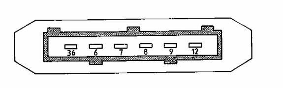
Electrical conductivity problems may be resolved by simple cleaning of the connector pins using a quality electronic component cleaner. It may be necessary to bend each male connector pins (in the MAF sensor housing) slightly to insure good connectivity. Pin layout is according to the figure below. Pin 36 is towards the front of the car. Pin identifiers may change from model to model, but the basic function remains the same.
Typical readings on certain conditions:
36 & 6 : Grounds
7 : ECU Ground
8 : Empty Connector
9 : 12 VDC Supply
12 : ECU Supply 5.0 VDC
Ignition on MAF disconnected (no start) Ignition on MAF connected (no start) MAF connected engine running @ idle (~750RPMs)
7 <1V (leakage) 7 >1V (leakage) 7 ~1.2V to 1.4V
9 Battery voltage 9 Battery voltage or slightly less 9 >Battery voltage due to alternator operating
12 ~ 5V 12 ~1.85V 12 ~1.8 to 2.5V
Diagnostics:
Battery voltages on pin 9 that deviates significantly from the chart need to be investigated further and repairs made.
Note: Should the battery be disconnected the engine management will need to re-learn the base idle. This “re-learning” is automatically achieved by operating the engine at normal coolant temperature and driving for a distance > 50 yards. The engine may stall at idle once or twice until the adjustment values are accepted and stored within the ECU RAM.
Pin 7 readings < 1.2V can produce poor running conditions and if lower possibly no start. A voltage of <0.2V or > 4.5V is will generate a diagnostic test code (DTC 12). Refer to Fault Code List for other diagnostic help with this fault.
Pin 12 reading will typically increase towards 5V as engine revolutions are increased. This reference voltage is from the ECU.
Bench Test (Circuit Checks) for MAF Sensor:
1) Remove the electrical connector from the MAF sensor.
2) Connect a 12VDC power source (battery) to Pin 9 (+) which is normal 12 VDC supply to the MAF sensor and Pin 36 (-) which is normal ground for the MAF sensor. Ensure the power supply positive is connected to Pin 9 and the negative is connected to Pin 36. Do not reverse power supply polarity.
3) Connect a quality digital multi-meter setup to monitor voltage to Pin 7 (+) and Pin 6 (-). Ensure multi-meter positive test lead is to Pin 7 and negative test lead is to Pin 6. If multi-meter polarity is reversed, voltages will indicate negative but the absolute values will be correct.
Test 1 : Air meter stationary with no flow
Test 2 : With a blast of air in the direction of flow
The mass airflow sensor is a metering device designed to determine the actual “mass” of air entering the engine. It is not a volumetric flow device and it does not require external air density compensation for proper operation. The engine must receive a mass airflow signal to account for changes in air density caused by temperature and altitude. A simple volumetric flow rate signal would be insufficient.
The meter itself, is between the air filter and the inlet manifold (looks like an aluminum tube with a rectangular box on top and a cable harness connecting to it). It is considered a very reliable component typically being trouble-free, and like the engine management computer, should never be condemned without thorough investigation. It performs it primary function of metering the mass of air drawn into the engine using two thermal sensors. These sensors are located within a bypass channel in the MAF sensor. One sensor is termed the “compensating coil” and is unheated while the other sensor is called the “sensing coil” and is electrically heated by the sensor circuitry. The amount of sensing coil current needed to keep the differential temperature between these two sensors constant is directly proportional to engine load (mass air flow).
The compensating coil is always at ambient temperature while the sensing coil is always attempting to create a fixed differential temperature as it is cooled by the air stream. In order to clean the sensing coil, the temperature flashes to 1000 degrees C for one second, four seconds after the ignition is switched off. The engine management computer is monitoring a voltage drop within the MAF sensor electronic circuitry, which is directly related to the current flowing through the sensing coil. This design is factory setup and calibrated. It is non-adjustable for the owner.
Early XJ40s incorporate a manual idle trim adjustment which is a 10 turn, 0-1000 ohm potentiometer built in to the air flow meter for minor idle fuel adjustment, but it works independently of the thermal sensors. Later models have adaptive idle fuel metering and no adjustment or input from the owner is necessary. These MAF internal adjustments, whether manual or automatic, are designed for emissions adjustment. The total available trim for either the manual or automatic idle fuel adjustment is only +/-10% of the nominal injector pulse duration at idle. Manual trimming is not recommended unless the owner has access to an emissions analyzer.
Functional Checks
Located on the left side of the MAF sensor is the six pin, rectangular electrical connector. This connector can be problematic. It cannot be over-emphasized that the engine management system utilizes low voltage control signals. These signals are subject to faults and high resistance joints caused by corrosion. To overcome this known problem, later models of XJ40s were equipped with gold plated connections. The connector is held in with wire clip. If you push up on the wire clip from underneath, the connector can be removed from the sensor.
Electrical conductivity problems may be resolved by simple cleaning of the connector pins using a quality electronic component cleaner. It may be necessary to bend each male connector pins (in the MAF sensor housing) slightly to insure good connectivity. Pin layout is according to the figure below. Pin 36 is towards the front of the car. Pin identifiers may change from model to model, but the basic function remains the same.
Typical readings on certain conditions:
36 & 6 : Grounds
7 : ECU Ground
8 : Empty Connector
9 : 12 VDC Supply
12 : ECU Supply 5.0 VDC
Ignition on MAF disconnected (no start) Ignition on MAF connected (no start) MAF connected engine running @ idle (~750RPMs)
7 <1V (leakage) 7 >1V (leakage) 7 ~1.2V to 1.4V
9 Battery voltage 9 Battery voltage or slightly less 9 >Battery voltage due to alternator operating
12 ~ 5V 12 ~1.85V 12 ~1.8 to 2.5V
Diagnostics:
Battery voltages on pin 9 that deviates significantly from the chart need to be investigated further and repairs made.
Note: Should the battery be disconnected the engine management will need to re-learn the base idle. This “re-learning” is automatically achieved by operating the engine at normal coolant temperature and driving for a distance > 50 yards. The engine may stall at idle once or twice until the adjustment values are accepted and stored within the ECU RAM.
Pin 7 readings < 1.2V can produce poor running conditions and if lower possibly no start. A voltage of <0.2V or > 4.5V is will generate a diagnostic test code (DTC 12). Refer to Fault Code List for other diagnostic help with this fault.
Pin 12 reading will typically increase towards 5V as engine revolutions are increased. This reference voltage is from the ECU.
Bench Test (Circuit Checks) for MAF Sensor:
1) Remove the electrical connector from the MAF sensor.
2) Connect a 12VDC power source (battery) to Pin 9 (+) which is normal 12 VDC supply to the MAF sensor and Pin 36 (-) which is normal ground for the MAF sensor. Ensure the power supply positive is connected to Pin 9 and the negative is connected to Pin 36. Do not reverse power supply polarity.
3) Connect a quality digital multi-meter setup to monitor voltage to Pin 7 (+) and Pin 6 (-). Ensure multi-meter positive test lead is to Pin 7 and negative test lead is to Pin 6. If multi-meter polarity is reversed, voltages will indicate negative but the absolute values will be correct.
Test 1 : Air meter stationary with no flow
Test 2 : With a blast of air in the direction of flow
The following users liked this post:
Rex L Harrisen (04-30-2015)
#7
01-28-2009, 09:19 PM
Think I identified the fuel pump relay and picked up a new one after work tonight and swapped them out. The relay makes a clicking noise for a few seconds after the key is turned to the on position without trying to start the car which I think indicates it is operating properly. I'm going to have to wait until this weekend to start tracing the fuel flow from the tank to the engine bay which i think is the next logical step. Thanks for your response.
Trending Topics
#8
01-28-2009, 09:26 PM
Join Date: Mar 2008
Location: Powell, Ohio U.S.A. 43065
Posts: 2,521
Likes: 0
Received 70 Likes
on
56 Posts
Hang on mate, when you said you heard the fuel pump run in your first post, that was when you were listening inside the trunk? You usually can't hear it otherwise, and it only runs for the same short period as your relay is energized unless you're cranking, when you can't hear it. Just to make sure, the fuel pump relay on a '92 is mounted on a bracket at the pedal box housing, under the hood. Are we on the same page?
#9
01-28-2009, 09:36 PM
Join Date: Mar 2008
Location: Powell, Ohio U.S.A. 43065
Posts: 2,521
Likes: 0
Received 70 Likes
on
56 Posts
Just a suggestion, since I know you are a good guy trying to help. Maybe it would work better to just say, "Have a look at JagLovers.org. Keep in mind that JagTechOhio often finds inaccurate or irrelevant information there that proud posters won't retract, so do your own editing".
A 1992 XJ6 fuel tank never collapses, and the pump is mounted inside the tank in a module with internal inlet and outlet check valves. The description of the externally mounted pump and check valveas written is applicable to1988-1990 only. That's as far as I read.
A 1992 XJ6 fuel tank never collapses, and the pump is mounted inside the tank in a module with internal inlet and outlet check valves. The description of the externally mounted pump and check valveas written is applicable to1988-1990 only. That's as far as I read.
#10
01-28-2009, 09:40 PM
We are on the same page. The relay was/is under the bonnet (is that the correct British term for hood?) on the drivers side close to the firewall on a bracket. I can only hear it if someone else turns the key while I am listening at the relay. Fuel pump can be heard from inside the luggage area, once again while someone else turns the key and I listen inside the luggage area.
#11
01-28-2009, 09:46 PM
Join Date: Mar 2008
Location: Powell, Ohio U.S.A. 43065
Posts: 2,521
Likes: 0
Received 70 Likes
on
56 Posts
OK, you have things right so far. Blocked fuel filter/ kinked fuel supply pipe/ incorrectly installed fuel pump/ faulty new fuel pump. Inspect in that order, PM me if you are stuck for parts. You can get a filter at Anvance Auto parts or similar for like $10.00. BE CAREFULL that you do not twist off the rusted, seized fuel lines when you try to unscrew the fittings from the filter.
#12
01-28-2009, 10:42 PM
For the complete electronic manual for your car follow this link pm Christo and get CD 2. Good luck these cars are a blast when they are running right
https://www.jaguarforums.com/m_85663/tm.htm
https://www.jaguarforums.com/m_85663/tm.htm
#13
01-30-2009, 07:40 PM
OK what I thought was the fuel pump running in the trunk must have been the power antenna or something else.
So when I discovered this I took the trunk apart to get access to the fuel tank and pump.
Low and behold the black wire and the red/blue wire had both been pinched and cut whenever the last person worked on the car and put everything back together.
So I got some blue and some black wire 14 gauge and some crimp joints with heat shrink and removed the bad section of wire and spliced in a good connection.
Now I can absolutely say without a shadow of the doubt that the fuel pump kicks on for a second and makes a "whirring noise".
Unfortunately this didn't fix my problem, car still won't start.
I replaced the fuel filter and left the connection from the tank to the filter off and tried to start the car. I didn't get any fuel to the filter. I tired this several times just in case it make take a while for the fuel to get back into the system after sitting idle for so long.
So I now know the problem is between the tank and fuel filter. I'll have to get the car up in the air tomorrow to investigate further.
There is a big rubber hose that goes from the tank to the fill neck area (overflow?). And there are 2 smaller had plastic hoses coming off the top of the tank. One looks like a vent and goes through a hole in the trunk and isn't connected to anything. The other runs along the tank in a groove under the tank straps and then connects to a 3-4 inch long piece of rubber with a couple of squeeze clamps which is then connected to another piece of hard plastic with a sharp bend in it (not kinked it is made that way) and it then disappears under the tank.
So I'll start my Saturday trying to find the blockage/problem.
#14
01-30-2009, 07:58 PM
Join Date: Mar 2008
Location: Powell, Ohio U.S.A. 43065
Posts: 2,521
Likes: 0
Received 70 Likes
on
56 Posts
None of the three hoses going to the tank that you described are fuel hoses, they are all vapor hoses. The fuel hoses plug directly into the bottom of the tank, visible as 90 degree fittings situated above the differential.
Now that you say you are certain that the fuel pump is running, and yet there is no fuel pressure at the inlet of the fuel filter, either the outlet hose from the tank is blocked in some way or the tank has to come out to see what went wrong with the previous pump installation.
Secifically, about the vent hoses:small left side is to a pressure relief check valve, separate it at the pinch clamps when removing the tank;
The other small black plastic pipe is an emergency pressure refief, to dump fuel on the ground instead of bursting the tank. It doesn't plug into anything at the bottom end. Leave that connected;
The larger rubber hose to the filler neck is to vent pressure to the neck while the tank is being filled. You don't have to disturb that at all, there's nothing wrong with it and it's not in your way.
#15
01-30-2009, 08:45 PM
Join Date: Jan 2009
Location: Tj�rn Sweden or Olso Norway
Posts: 179
Likes: 0
Received 5 Likes
on
5 Posts
Stupid question of me perhaps but do you have any spark?
If you dont have any spark it´s almostcertainly the CPS (crankshaft positioning sensor) that has gone bad.
It sits mounted on the front of the engine reading from the harmonic balancer they breakdowm quite often.
If you dont have any spark it´s almostcertainly the CPS (crankshaft positioning sensor) that has gone bad.
It sits mounted on the front of the engine reading from the harmonic balancer they breakdowm quite often.
#19
01-31-2009, 07:56 PM
Join Date: Mar 2008
Location: Powell, Ohio U.S.A. 43065
Posts: 2,521
Likes: 0
Received 70 Likes
on
56 Posts
That's true, but the guy would have had to cut the link lead wires because the terminals are different sizes so you can't mess it up.
My guess is that the pump came out of the lid when he put the module back together, so the pump is running but it's just pushing the fuel out inside the module and not out through the module outlet and to the outlet hose.
My guess is that the pump came out of the lid when he put the module back together, so the pump is running but it's just pushing the fuel out inside the module and not out through the module outlet and to the outlet hose.
#20
01-31-2009, 08:15 PM
OK so I got the car in the air today and traced fuel line from the filter to the tank. No kinks, leaks, or any other issue noticed.
Blew air through the line from the filter that goes back to the tank (not sure if this was wise or not, but I did it anyway after debating it with myself for awhile) This allowed air into the tank and to build up pressure in the tank. But it didn't unblock anything or allow fuel to start flowing. So at least air can move through the line.
So unfortunately at this point I think I have a fuel pump or fuel pump install problem.
When you're in the trunk on the side or back of the fuel tank there is a clear or opaque circle/plug that has a few wires connected to some leads attached to the circle/plug. I'm going to assume this is the fuel level indicator.
Anyway when you put the key in the ignition and attempt to start the car and the fuel pump runs for about a second you can see through the circle/plug that it causes the fuel to bubble, perk, move or whatever you want to call it just for the split second that the fuel pump runs.
So if anyone has anything else they think I should check I am all ears. However I think it's time to pull that tank. With that said, if anyone has the procedure written down I would welcome you sending it to me. Otherwise I'll be buying a manual online tonight or tomorrow and tackle this issue next weekend.
While I'm pulling the tank are there any other collateral jobs/maintenance I should do in conjunction with it?
Thanks to all for your help so far.