
Rebuilding the fuel lines
#1
 06-04-2013, 08:59 AM


I'm finally returning to the XJ6 (1985) that has languished in the bodyshop (quality, price and speed: pick 2) since Nov. The tanks were dropped and new ones purchased in while it was in there (so the Por15 can be put every-which-where it should go).
Unfortunately, I don't have a terribly good manual for verifying the fuel plumbing is rightly restored. When I purchased the ol' girl, the DPO had plumbed the fuel pump directly into the RH tank, and so I need to verity he didn't screw around with anything else and I need to restore her to the original lines.
Does anyone have a favored collection of images/diagrams, etc. that they'd recommend I start with?
I'm starting with:
An old Haynes guide to the Series 1,2 and 3 (not my fav. resource).
What I can scrounge from A6: Fuel injection and the Jaguar XJ6 4.2 Series 3 / AJ6 Engineering
I'm afraid the search on this forum is rather target-rich for fuel line discussions.
#2
06-04-2013, 09:44 AM
Veteran Member
I've been using the parts manual mentioned in this thread...... https://www.jaguarforums.com/forum/x...iagrams-95362/
Extremely useful. There are 4 diagrams of the various parts in the trunk required for a "proper" fuel system.
I have an original unmolested '84 car which I believe to be completely correct in the fuel tank department.... if you need pictures of the trunk area, let me know and I'll snap some for you
Extremely useful. There are 4 diagrams of the various parts in the trunk required for a "proper" fuel system.
I have an original unmolested '84 car which I believe to be completely correct in the fuel tank department.... if you need pictures of the trunk area, let me know and I'll snap some for you
#3
06-04-2013, 10:05 AM


#6
06-04-2013, 05:08 PM

Veteran Member
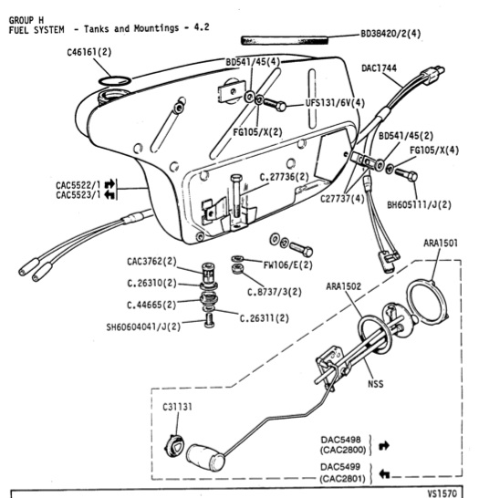
The diagrams supplied here omit the pipes from the two tanks to the fuel supply changeover valve. Unforunately, I don't have a diagram, but it will be in the same publication as the others have come from.
Having pulled everything apart in this area around 1992 prior to a major panel replacement job, I can tell you that on each side there is a fairly short 3/8 OR 1/2" diameter pipe. (About 4-5" long) coupled to the lower inner side of the tank, crossing the bottom, (open side) of the exhaust space, then into the lower boot (trunk) side via a hole about 1" in diameter with a protecting grommet. Having now got a pipe each side from each tank protruding into the lower trunk space, (behind where the spare wheel goes, and protected by a cover), the fuel change-over valve is mounted nearby. The two pipes are coupled to the valve using the usual fuel hoses, and then the changeover valve is coupled to the pump which is mounted on an anti-noise and vibration mounting. The exit pipe from the pump is then attached to the fuel supply pipe.
So that's the fuel supply arrangement, the fuel return pipes never get into the trunk space, they get to the tanks at their front via the inner wheel arches where the other changeover valves are found (as per diagram)
#7
06-05-2013, 11:33 PM

Trending Topics
#8
06-06-2013, 07:40 AM

Senior Member
FastKat,
Sure thing. I had success removing that three-way valve you describe in my 2nd car, a green 84 XJ6, when the PO advised not using the right tank due to some corrosion (surprise) in order to prevent myself (or someone else) accidentally pulling from the wrong tank or letting a loose sealing valve leak a little dormant water from the bad tank to the good tank/fuel lines.
Edit:
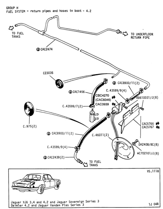
Don't know why I didn't include this one in the original post but here is a diagram showing what connects to the changeover switch, from where, and where it is going. Unless I'm much mistaken, this is the diagram to which Fraser Mitchell is referring above. Hope it helps.

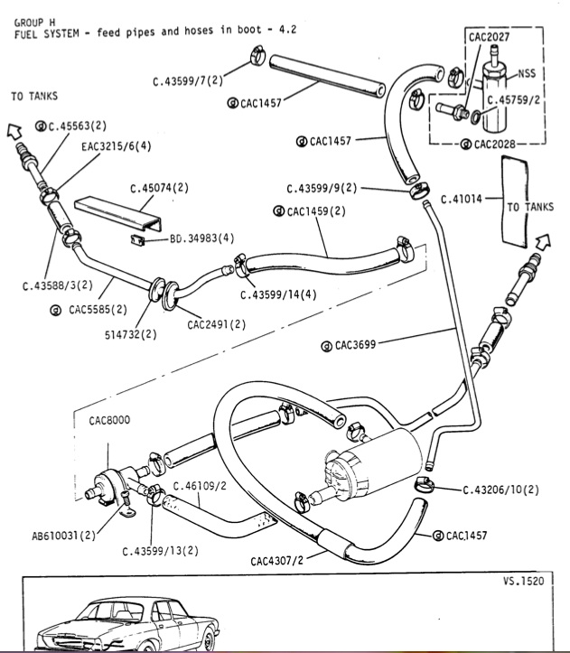
This part ^ is part no. CAC8000, depicted in the bottom left corner of this one
|
V
Sure thing. I had success removing that three-way valve you describe in my 2nd car, a green 84 XJ6, when the PO advised not using the right tank due to some corrosion (surprise) in order to prevent myself (or someone else) accidentally pulling from the wrong tank or letting a loose sealing valve leak a little dormant water from the bad tank to the good tank/fuel lines.
Edit:
Don't know why I didn't include this one in the original post but here is a diagram showing what connects to the changeover switch, from where, and where it is going. Unless I'm much mistaken, this is the diagram to which Fraser Mitchell is referring above. Hope it helps.
This part ^ is part no. CAC8000, depicted in the bottom left corner of this one
|
V
Last edited by john_cook12; 06-06-2013 at 07:51 AM.
#11
06-06-2013, 11:15 AM
Sorry for the confusion guys - when I said "3-way check valve" I did not mean the fuel tank selector... I meant the CAC2028 check valve that burps air back to the return system and also serves as a one-way check valve to maintain fuel system pressure after shutdown. I really don't know what to call that thing - I think it's a relatively trouble-free part, so there's not much documentation on it.
Whatever it's called, I think I am going to bypass it and run 3/8" hose from my pump directly to my new 3/8" fuel filter. I have a supercharger that demands high flow at a very high pressure, and a little extra flow capacity will help the fuel pump deliver.
BTW, on my 1985 XJ6, most of the pressure side connections (from the outlet of the fuel pump through the fuel filter) are all 5/16 fittings, 5/16 steel line, and 5/16 hose. The fuel pump and the fuel filter have 5/16 hose barbs. However, the steel fuel line that runs from the spare tire well to the engine seems to be 3/8" when measured with a caliper. I think the 5/16" hose is simply forced over the 3/8" steel line that protrudes into the spare tire well. I dealt with this about a year ago when I replaced all the dried-up hose with new 5/16" high-pressure fuel hose.
#12
11-23-2013, 10:45 AM

Junior Member
Join Date: Nov 2013
Location: boston
Posts: 2
Likes: 0
Received 0 Likes
on
0 Posts
I'm experiencing a fuel leak on the right side of my 85 xj6. Don't know the source yet but it appears to be a tank overflow. I suspect that the right side return valve may no be closing or functioning properly. The return piping to the tanks is mostly hidden making my inspection difficult. I'm trying to avoid dropping the tank(s). What happens if the tank change over valve is eliminated with a tee and both return valves are eliminated with tubing? Won't both tanks then act as a single tank and seek a common level? In other words the fuel pump will be always be drawing from both tanks and returning to both. A less complicated configuration and the selector switch isn't necessary. I don't see any obvious problems with this. Any thoughts or comments?
Lee
Lee

Thread
Thread Starter
Forum
Replies
Last Post
1964Daimler
MKI / MKII S type 240 340 & Daimler
4
09-09-2015 04:50 PM
Currently Active Users Viewing This Thread: 1 (0 members and 1 guests)

