When you click on links to various merchants on this site and make a purchase, this can result in this site earning a commission. Affiliate programs and affiliations include, but are not limited to, the eBay Partner Network.
Vacuum line replacement pics :: In glorious technicolour
So, I finished replacing all the vacuum lines as part of my lumpy idle campaign.
I got a lot of help from the forum, including diagrams, so I thought I'd take a few pics which may help others if they try the same thing.
I bought a complete silicon hose kit from ebay, which came in a variety of sizes. I also went a bit crazy with the colour, but at least I can see them now :-)
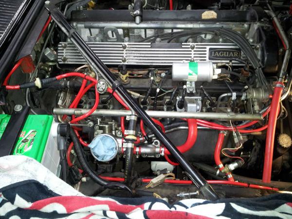
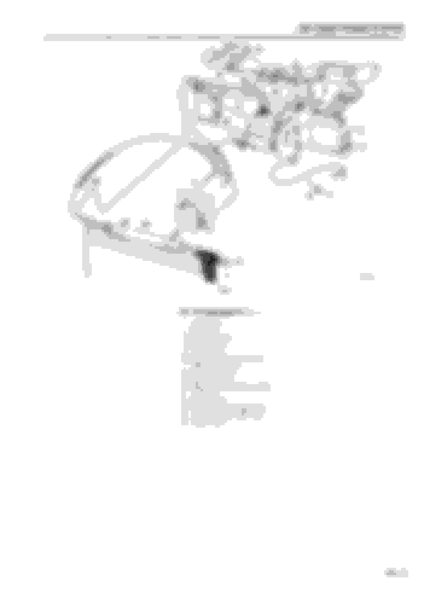
Plenty going on on the right hand side of the engine.
Airbox and mass flow sensor removed (obviously)
The 2 larger pipes on the right hand side of the throttle body (one of which goes to the idle adjuster block and the other to the breather on the front of the engine) were pretty mangled.
The thin line running top to bottom of the shot is actually on its way to the distributor advance. Originally all of this was run underneath the inlet manifold and completely out of site. I moved everything out of there with the thought that if something falls off or goes wrong in future, it should be easier to notice it
Thicker pipe with the solenoid in the middle goes to the charcoal canister in the front fender. Other thick pipe not connected at one end goes to the (removed) airbox
One of the most difficult parts was getting to the distributor vacuum regulator, which is normally hidden underneath the inlet manifold. I thought this over for a long time but eventually I concluded the safest way to replumb it was to relocate it to somewhere I could see it. So it's now attached to the cross member.
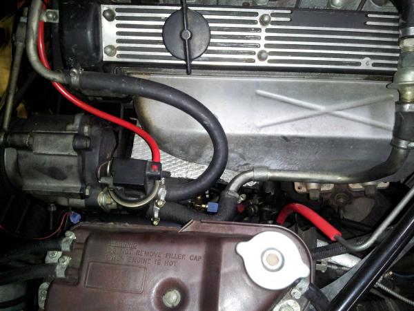
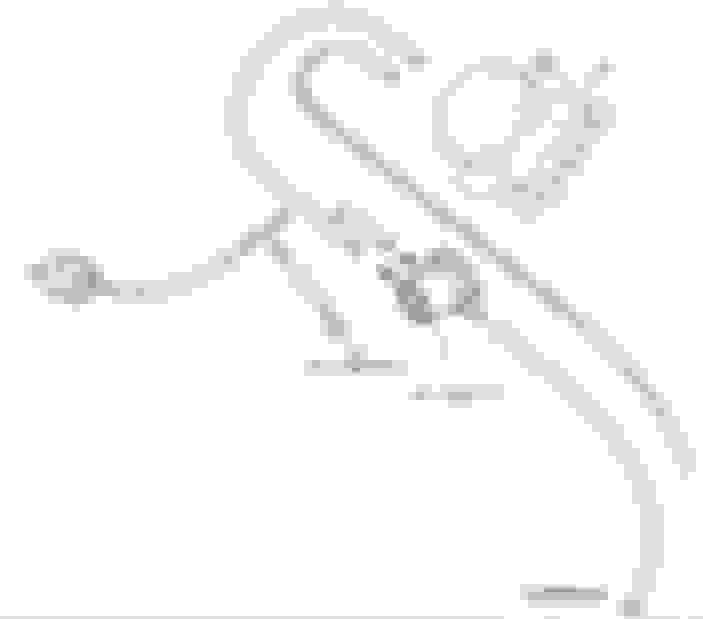
Left Hand side...... not much to see..... 1 line running round the front of the engine to the smog pump. One line running from the metal line to cruise bellows.
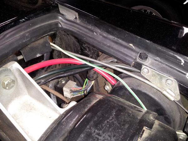
One line running along the top of the firewall to the vacuum reservoir
I'll report back once I get everything back together and see if I've made anything better or worse :-)
I have that same set saved on my home page on E-bay!
I plan to do the same exact thing to my engine.
Now, I know exactly how cool it will look!
Thanks for sharing!
My SII had a bunch of lines that ran into the car - when any of them
cracked or fell off - idle was changed....many different and odd sizes
compared to modern cars today.
One line running along the top of the firewall to the vacuum reservoir
I'll report back once I get everything back together and see if I've made anything better or worse :-)[/QUOTE]
What does the line from the vacuum reservoir connect to? From my reading, looks like it should "T" into a line that runs between the distributor vacuum regulator and the vacuum to the firewall/Delanaire.
The main reason I got the kit was because I couldn't be bothered trying to work out and measure all of the different hoses
@Noah
That vacuum line comes round and goes through what looks like a check valve, then eventually goes to the manifold vacuum connection. In the first picture in the post you can see the line coming across the firewall, then the filter thingy which is just above the battery
Wow! I had a look on eBay. These guys give you $20 back if you send them a pic of the kit installed in your Jag. Only if it's the bright colored ones though! I dunno, it's a bit out there this red! Looks great though. Idle any better by the way?
Thanks for the reminder..... I didn't take the pics to help the board, I just took them to get some $$$$$ :-)
My car is very original so I was a little bit reluctant to change the hoses to red, but in the end I allowed myself to have a little bit of fun with it. Once the air box is back on it actually hides most of the hoses anyway. Along the same lines of originality, I am ok with the relocation of the 3 way valve because it's just a lot more sensible to put it where you can see it.
The idle smoothness has improved. I haven't had it out on the road yet to see if the trip computer instant mpg is now going to show 99 (instead of the previous 50~60). I still have the petronix dizzy, coil, leads and plugs to change, which I will hopefully get to this weekend.
If you put them on - send some pics!
I plan on it, but I have to wait - still working the final drive overhaul. Not enough cash to buy everything I need at once...
In my quest to clean up and understand the engine bay of my 86 US SIII, I want to replace all of the vacuum lines, replace some related components and re-route some lines as needed. I read the parts manuals and saw a few diagrams, read a great post showing all of the lines in red (search forum title-only for "in glorious technicolour") and studied the stickers under my bonnet. Alone, they all don't quite paint a 100% clear picture... at least in my unclear brain!
Of course I suspect there are several differences in US/non-US versions and even by year. But my selfish wish is a definitive connection diagram for an 86 US SIII. I also used my own car as another example, but you never know what a previous PO/shop has done to the connections. So with no further delay, I submit the attached picture as a starting point for comment. I welcome any corrections, objections or other education that will help me understand this. Below I also have listed some thoughts/notes based on my digging into this and please feel free to pounce on those too
First comment will most likely be that I DO NOT have every "vacuum/air" related connection shown, for example, the breather unit and pipe is not shown, nor some of the "extra" air connections, nor the gas tank venting. I will get to those and I omit some of the items mentioned because I have not yet removed my air cleaner and throttle body to see what lurks under there.
I think the layout in the diagram is self-explanatory and many of the items are fairly simple, like the cruise and smog vacuum connections that go directly to fittings on the intake manifold.
For the fuel rail connector to the pressure regulator and intake manifold, I need to look up what that part is on the fuel rail with the two vacuum connections and label it.
I did not delve into any connections west of the bulkhead inside the dash.
The biggest fuzzy area in my head (and the various posts/diagrams) seems to be the connections related to this flow:
- Distributor vacuum regulator
- "T1" and its connections to the bulkhead climate vacuum supply line, vacuum reservoir and one way valve
- "T2" and its connections to one way valve, intake manifold and distributor vacuum regulator
Starting with "T1", it makes complete sense to me that "vacuum" is being supplied to the climate control and to the
climate control vacuum reservoir... and that the one way valves purpose is to keep vacuum in the vacuum reservoir when the engine stops running. In fact I believe I read that is the whole purpose of the vacuum reservoir.
"T2" provides the intake manifold vacuum to "T1", but also provides the manifold vacuum to the "delay" port on the distributor vacuum regulator. There is an excellent write-up in the FAQs by "Vilas" explaining the design, purpose and how to test that distributor vacuum regulator. But somehow it *seems* that the difference between the "Carb" and "Delay" port levels triggers an internal valve in that regulator to affect the vacuum advance on the distributor. But I have not yet gotten my head around the exact mechanics of it all. I attached a screen shot of that post.
This post I am updating now has all the "red" pictures of the vacuum lines but I am also adding the other pictures I referenced in my investigation so everything is in this one post.
Great that you went back and posted about the details of your project. It would be great if everyone who asks for help came back and added to our knowledge base so enthusiasts years from now can find everything they need in one place.
Just a quick followup.. I managed to remove the vacuum line on the distributor and pull the vacuum regulator and associated connected vacuum lines UP from under the manifold. I plan to keep it all routed "above ground".
Also, when I did that I was able to verify that my blue drawing above has the proper connections to both "T1" and "T2", so happy I could make sure that was correct. Now that I have ripped out all of the vac lines, I will replace and hope to hell she starts up still.. and *maybe* idle a bit more smoothly.

 06-18-2013, 12:23 AM