When you click on links to various merchants on this site and make a purchase, this can result in this site earning a commission. Affiliate programs and affiliations include, but are not limited to, the eBay Partner Network.
An Epic Troubleshooting Guide for Climate Control HOW TO
The S-Type climate control system generates a lot of queries on this forum. Typically, the complaint is low cooling from the AC, heater stuck on, or erratic behavior. While the automatic control system adds a layer of complexity, troubleshooting is fairly straightforward. If you follow this troubleshooting guide, hopefully we can save you some time, money, and aggravation.
Please follow the steps in order. Don't just skip around, hoping for the best. None of these steps are difficult, and following them in order should lead to a correct diagnosis. This guide is written in my typical verbose style. I've never been one to eschew obfuscation. Pour yourself some coffee as this will be a long read. I was that annoying kid who always asked "Why?". I'm not going to just tell you what to do. With any luck, I'll help you to understand why, too. And if you don't like it, you're perfectly welcome to close this guide and load the parts catapult (Pull!) for troubleshooting.
Most of this guide was written with my '02 V6 model as a guinea pig. There are some minor differences with later models or the V8 engine, but the basic principles should be similar. Also, I've concentrated on external components, mostly inexpensive sensors, that can cause problems. I haven't delved too deeply into the basic (read: expensive) components like the compressor, condenser, etc., as they are fairly reliable. Consider this guide as covering about 80% of the likely faults. If your troubleshooting leads to an expensive conclusion, I'd suggest getting a professional opinion instead of relying on just the advice of some guy on the internet, no matter how smart he may think he is...
All measurements are given in SAE terms. To keep things simple, I have not included any Metric readings. If you'd rather convert, this link has you everything you need to know about using the Metric system:
Clip the pocket thermometer in the center dash vent. Before starting any troubleshooting, record the actual duct and outside air temperatures during your typical drive. It does no good to say the air feels "warm" or "cool". We need an actual value, and also need the outside air reading for comparison.
Before we dig in, please allow me to present a bit of my general troubleshooting theory. This applies to all fields, not just S-Type climate control. In my little world, I firmly believe an amateur mechanic can do a job every bit as good as the professional, often better. The pro works under time constraints, and can't spend a lot of time troubleshooting. We DIY folks have a huge advantage because our time is essentially free (to a point), and can go more in-depth than the pro. We can also gather data over a long period of time, where the pro can only rely on what is currently in front of him. I also like to consider probabilities of certain failures, and concentrate on the more likely ones. If troubleshooting leads to two equally likely faults, and one option is less expensive or easier to accomplish, I'll generally go that route first. I'm lazy and cheap, and proud of it. [\Soapbox mode off]
Hope I haven't lost you yet. I'd like to thank the many kind members of this forum for their patience and depth of knowledge. I've taken many of the suggestions offered and experimented with them myself. In some cases, I've tweaked them slightly for accuracy or ease of use. This guide is a compilation of the good advice offered here, organized in a manner that is hopefully easy to follow based on symptoms, with side dishes of probability and my overly-inflated opinions.
A bit of background on the S-Type climate control system is in order, to help you with troubleshooting. Because the heating and AC systems are interconnected, this guide will cover problems with both. The AC system is fairly conventional, but possibly quite different than what you may have worked on in the past. You've got a compressor, a condenser (at the radiator) on the high pressure side, a thermal expansion valve (on the firewall) to drop the pressure back down, and an evaporator (in the dash) to actually make things cold.
If you're like me and keep forgetting the difference between the evaporator and the condenser, think of evaporation making you feel cold, such as when stepping out of the shower. Sorry for the mental image of yours truly towelling off, but this little memory trick has always worked for me. We will cover AC controls later. For now, just be aware the system can be controlled automatically or manually, which we can use to great advantage for troubleshooting.
So assuming (Danger! Danger!) the AC system is in good working order and making lots of cold (forgive my technically inaccurate terminology), what happens next? All air to the cabin is first routed through the evaporator. That same air, after leaving the evaporator, is next routed through the heater core, which we'll cover next. On a warm day, when only cooling is wanted, hot coolant flow (from the engine) to the heater core is shut off. So even though all cabin air is always flowing through the heater core, if the coolant inside is not hot, no heat is transferred to the cabin air. This is different than most vehicles, which use a blend door to divert air around the (always hot) heater core to control the heat output into the cabin.
The heater core is a special split model to allow different temperature settings on each side of the cabin. It's basically two heater cores in a common housing, with a separate input for each side and a common return. Coolant flow through the two sides is controlled by the Dual Coolant Control Valve (DCCV). The DCCV is buried between the radiator and the right front fenderwell. The DCCV has two electrically controlled valves, one for each side of the heater core. The two valves are spring-loaded open. The logic here is in the event of a control failure, the default position allows heat to the defroster for safety. Please be aware the DCCV has a very high failure rate. Despite the spring-loaded action, crud builds up in the coolant passages and the individual valves can jam in any position, allowing no heat, too much heat, or a constant somewhere in the middle. If the valves aren't fully jammed, their range of motion can still be restricted by crud buildup. On 2003+ cars, a failure of these valves can also overload the control panel and burn it out, another common failure. We're getting a bit ahead of ourselves, but this can be repaired at reasonable cost, so don't go into FullPanicMode� just yet.
What about a cold day, and you want heat? The two valves in the DCCV are electrically commanded open (power off), and hot coolant is routed through the two halves of the heater core. This abundant source of heat (from the engine cooling system) is transferred through the HVAC ducts into the cabin, and you can take off your coat. Also, when the system is in automatic mode and the exterior air temperature is above 27F, the AC runs at a low level even when heat is being supplied. This helps dry the cabin air for comfort and to limit condensation on the windows.
Let's look briefly at the HVAC automatic controls. The cabin has a single temperature sensor, located behind a small grill above the ignition key. The cabin ductwork has a venturi to create a slight vacuum at this grill and draw in cabin air for sampling. This sensor is one of the main inputs for the Air Conditioning Control Module (ACCM, the control panel) to command heat or cooling for the cabin.
A dual sunlight sensor is installed near the front edge of the dash, at the base of the windshield. It detects the amount of sunlight reaching each side of the car. When the sunlight is even, this sensor signals the HVAC system to slightly lower the output temperature on both sides to compensate for the extra heat input from the sun. When the sunlight is concentrated on one side, the output temperature is reduced only for that side.
An external air temperature sensor is located behind the front bumper. This sensor helps the controller determine how much heating or cooling to supply. This sensor also feeds the external temperature display on the control panel. When the engine is shut off warm and then restarted within an hour, the display shows the last recorded value for a while to minimize any errors from heat soak.
Remember that dual heater core, which allows different temperature settings on either side of the cabin? There's only the one cabin temperature sensor, located on the driver's side. How does the HVAC system know how to control the passenger side? It doesn't directly know. It makes a reasonable guess based on outlet duct temperatures. The outlet ductwork is split in two, and each side has its own temperature sensor. On a cold day, when heat is commanded, if one side has requested a cooler setting, the DCCV restricts coolant flow to that side. On a warm day, when AC is commanded, the DCCV shuts off coolant flow to the cooler side, and adds an small amount of heat to the side with the warmer setting. Pretty slick, huh? Remember that last bit, though. Under many circumstances, heat is intentionally added to the cold AC output. That's fine when wanted, but not if the heat sticks on.
Almost ready to dive in and start changing expensive parts? Hold on, let's look at the controls for the AC system, the compressor and all that stuff under the hood, that makes the cold at the evaporator in the dash. Notice I keep using that somewhat inaccurate term "making cold". For troubleshooting, we don't really need to know all the inner workings with fancy terms like latent heat and so on. We only need to know when the system has the proper amount of refrigerant, the compressor moves it at varying pressures (a high side and a low side) through a closed cycle, heat is expelled at the condenser, and the evaporator "makes cold" for the cabin.
Control of the compressor, and thus the movement of the refrigerant, is different from most vehicles. For example, the low side pressure is the primary control input on most vehicles, but not the S-Type. Ideally, the evaporator should operate just above freezing. Any colder, and ice will form on the outside of the fins where air to the cabin passes through. "Ooh, ice is cold, that must be good, right?" Nope, not in this case. Strange as it may seem, because ice make an excellent insulator, it will actually reduce the amount of available cooling to the cabin. Too much ice accumulation can actually block off cabin airflow completely, causing cooling to drop off dramatically. For maximum cooling efficiency, the evaporator temperature should be controlled slightly above freezing, generally 34-36F to leave a little margin.
If you've done much AC work on other vehicles, you may be familiar with a pressure switch in the low side. The pressure at this switch directly corresponds to the temperature at the evaporator. Once the compressor draws the low side down to the proper point, the pressure switch turns off the compressor clutch to prevent ice accumulation at the evaporator. Stone age stuff. There is NO low pressure switch on the S-Type. The evaporator is kept above freezing by directly measuring the temperature, versus extrapolating from the refrigerant pressure. A temperature probe, installed just downstream of the evaporator (and before the split heater core), signals the controller when to shut off the compressor. This evaporator discharge sensor is not an on/off switch, but a variable sensor feeding a temperature signal to the controller. This sensor is one of the main inputs for control of the compressor clutch.
Remember the split cabin ductwork, with a temperature sensor on each side downstream of the heater core? Those two duct temperature sensors are identical to this evaporator discharge sensor. Getting ahead of ourselves again, but we can use this to our advantage for troubleshooting. The two duct temperature sensors are only used in automatic mode. The evaporator temperature sensor, however, is used in automatic AND manual. That's important to remember. If the two duct temperature sensors have a problem, the AC can still run in manual. If the single evaporator temperature sensor acts up, the AC will not work properly no matter what mode is selected.
Is your head spinning yet? The compressor is an advanced scroll design with an internal bypass valve that helps control the low side pressure. This is a BIG difference from other designs. The bypass valve senses the low side pressure. When this pressure is not low enough, and more pumping action is needed, the bypass valve will close for maximum compressor output. When the low side pressure is in the correct range and less pumping action is needed, the bypass valve opens proportionally and the compressor output is reduced. Pretty slick, huh? We'll talk more about this bypass valve later, including a factory approved modification that tricks the compressor into max mode all the time. For now, just the remember the original configuration assists with low side pressure control and is self-regulating to some extent. Compare this to other designs that only have maximum output and must be switched on/off more frequently. Less cycling means longer clutch life and less variations in engine load, for smoother operation and improved fuel economy.
One area we won't cover much is how pressure is reduced from the high side to the low side. If you're familiar with a system with a fixed orifice, as found on many vehicles, you may as well get those brain cells labotomized. The S-Type version uses a Thermal Expansion Valve (THX). From what I understand, this valve is very reliable. On the slim chance is does need replacement, it's a major job involving removal of the dash. Based on the probability/difficulty ratio, I'm going to gloss over this one. Just be aware how it works. This is a self-adjusting variable restrictor that controls the flow of refrigerant through the evaporator by sensing the temperature. Ideally, you want the proper amount of internal flow to keep the evaporator just above freezing. Too cold? The THX slows down the refrigerant flow to reduce cooling. Too hot? The THX increases the refrigerant flow to (wait for it...) increase cooling. If you had AC on your car back in the 70s, you may have seen a variation of this valve under the hood, with a remote sensor at the evaporator, at the end of a long fragile capillary tube:
The S-Type THX is a much more compact and robust design, mounted directly on the evaporator. Rather than using a remote sensor, the valve monitors the temperature internally. Purloined from Rock Auto, this image shows the compact nature of the valve, with an internal temperature sensor to monitor the refrigerant temperature as it leaves the evaporator:
Feeling pretty darn smart by now, huh? Hold on, there's one more component to discuss. Although the S-Type doesn't have anything directly monitoring pressure on the low side, it does have something on the high side, called an AC pressure sensor. Instead of going to the ACCM, the high side pressure value is fed to the Powertrain Control Module (PCM) as part of the normal control of the compressor clutch.
If the pressure rises too high (420 psi), the AC pressure sensor will signal the PCM (not the ACCM) to shut off the compressor before reaching the danger point. This sensor is also part of the control system for the electric fan, as airflow through the condenser is a major controlling factor for high side pressure.
When the AC system is off, pressure will equalize on both sides. In the event of a major leak, the pressure will drop too low and the same AC pressure sensor tells the PCM there is not enough refrigerant available to run the system. Under this condition, the PCM will not energize the compressor clutch and AC will not be available.
As a quick review, it's important to keep the evaporator temperature just above freezing. Three components work together for this goal:
1) The evaporator temperature sensor sends a direct reading to the ACCM, which talks to the PCM for control of the compressor clutch.
2) The self-regulating compressor will reduce output when the low side pressure gets too low. This is only applicable to an unmodified compressor.
3) The THX adjusts refrigerant flow to regulate evaporator temperature.
In theory, the three components work together in perfect harmony. In the real world, however, it's possible for one component to have enough control range to hide a fault with another. In other scenarios, they could fight each other and cause erratic operation.
Have I bored you to tears yet? Itching to start randomly changing parts and hoping the problem goes away? No joy, as I'd like to review a few common failure modes. Trust me, this will help when you actually start troubleshooting. Also, we should discuss differences when the climate control system is switched from automatic to manual mode. Manual mode bypasses inputs from some (but not all) sensors and is a gold mine for troubleshooting.
Automatic mode is the normal setting on the control panel, and the light at the AUTO button should be illuminated. If not illuminated, press the AUTO button once to return to automatic mode. If all is working properly, the HVAC system will then heat or cool the cabin as required to meet the selected temperature. Technically, any time the AUTO light is off, the system is in manual mode, but that doesn't help us much.
For an AC problem, toggle the temperature selector down until LO is displayed. The fan speed will increase, both valves within the DCCV are commanded closed (full power), and the AC system will provide as much cooling as possible.
For a heating problem, toggle up until HI is displayed. Once again, the fan speed will increase, and both valves within the DCCV are commanded open (no power) for maximum heating. Curiously, the AC still operates at a low level to reduce humidity, unless selected off.
"Can I start changing parts yet? Can I? Can I?" Almost there, be patient. Before diving in, it's very important to underside an important distinction. Consider the common problem of not enough cooling from the AC system. Two things have to happen before you'll feel cold air on your face:
1) The underhood portion of the AC system has to be "making cold" in sufficient quantity at the evaporator. This requires the proper quantity of refrigerant, adequate compressor performance, etc.
2) Both valves in the DCCV have to be closed or heat will be dumped into the cabin ducts. If one side of the cabin has a higher selected temperature, it's okay for that side of the DCCV to modulate open slightly, but the colder side must be fully closed.
So let's say your AC system has a slow refrigerant leak, a common situation. The system still "makes cold", but only at a reduced volume. The cabin may even feel cool enough on all but the hottest days. Notice how a DCCV sticking open can mimic these symptoms. Meanwhile, your cousin's barber had the same symptoms with his S-Type, and a new DCCV fixed it for him. Same symptoms, must be the same root cause... Why bother investigating? Let me know how that works out for you. Hopefully you'll get suspicious by the third DCCV.
This distinction is so important, I'll repeat it: For an AC problem, you must make sure the underhood portion is "making cold" in sufficient volume, and the DCCV is not inadvertently dumping extra heat into the cabin. These are the two factors in the cold air equation. You could replace every component in one portion and gain nothing if the root cause is in the other portion. Remember, all cabin air travels through the split heater core, even when no heat is requested.
Please consider the possibility of multiple faults. After identifying and repairing any fault, retest the system and see if the symptoms have changed. If so, follow the troubleshooting procedure for the new symptoms. Don't be alarmed to discover more than one problem. It just means you've made some progress but have more work to do.
This troubleshooting guide is a work in progress and does not cover all possible situations. For instance, this guide may help you zero in on a particular sensor, but for now you may have to find the exact specifications yourself. Also, I haven't covered the doors and actuators for the cabin ducts. Judging by the forum reports, they are very reliable and I have no experience with them, so I've left them out for simplicity. To test them, manually set the fan speed to high and play with the door buttons at the bottom of the control panel. As long as air goes where requested, the doors and actuators are fine.
Follow this link, courtesy of Gus at JagRepair.com, for a 2002 training guide with lots of details about the system. This covers multiple models, so scroll down to section 3 for the S-Type. Please note many of the component details in section 1 (Introduction) don't apply to the S-Type, but that is not clearly noted:
Almost there. Raise your right hand and repeat the S-Type HVAC Troubleshooter's Oath: "I (insert name), do solemnly swear to follow all appropriate steps in this troubleshooting guide. Furthermore, I promise not to skip around and if this guide works for me, I will post useful comments to help others."
Let's start by confirming your fault. Remember way back at the beginning when I had you clip a thermometer in the center duct? Oh sure, that was a long time ago and the kids have all grown up and moved out since then, but surely you remember. Keep track of that reading for the next steps. For the most effective troubleshooting, take your duct temperature reading on a test drive of at least 10 minutes moving at least 30 MPH. That forward motion is needed to ensure good airflow through the condenser. The electric fan kinda sorta does it when stopped, but ram airflow is way more effective. A duct temperature readings taken in your driveway is not going to be the same as a value recorded on a test drive, and that's what we really need. So for most of our troubleshooting, take your temperature readings on a test drive whenever possible.
Start by selecting the most appropriate description of your symptoms from the list below. For the term "inadequate cooling", please consider that to be anything above 38F at speeds over 30 MPH. Below that speed, it's okay for AC output to creep up to approximately 45F on hotter (95F+) days.
A) Everybody gets to run the first test, to verify proper operation of the DCCV. Don't skip this one, as it affects both heating and cooling. Go to post #2.
B) Insufficient/erratic heating or cooling in automatic mode. Okay in manual. After completing post #2, go to post #3.
C) Insufficient cooling from the AC system in automatic or manual mode. Duct temperature lower than exterior air. After completing post #2, go to post #4.
D) No cooling from the AC system in automatic or manual mode. Duct temperature equal to or higher than exterior air. After completing post #2, go to post #5.
E) No heat in automatic or manual mode. After completing post #2, go to post #6.
If you'd like troubleshooting assistance, please start a new thread instead of replying to this one. Please limit replies in this thread to general troubleshooting concepts, additional tips, lessons learned, etc.
Verify Proper Operation of the DCCV - Everbody Do This Test
Please start with the introduction (Post #1 above). After that, no matter the symptoms, everybody gets to do the steps in this post:
Verify proper operation of the DCCV
The DCCV can be a problem child. Before doing anything else, let's make sure the two valves in the DCCV operate properly. If these valves stick open, even partially, hot coolant will reach the heater core and heat will be dumped into the cabin. If stuck closed, no heat will be available.
Courtesy of forum member Caveforce, here's an extreme example showing a clogged DCCV:
Remember, these valves are spring-loaded open, and a steady 12V DC input is required to close them. Start by checking the DCCV fuse.
For a pre-facelift car (1999-2002), check fuse #1 at the Front Power Distribution Box under the hood:
For a post-facelift car (2003+), check fuse F32 at the Front Power Distribution Box:
We will run some additional electrical checks later. But for now, let's check to see if the DCCV is sticking open, even if commanded closed. Two methods are available to test if both valves are fully closing. The second method is preferred.
For both methods, make sure the coolant level is correct. Especially on V6 models, low coolant can cause a reduction in flow to the heater. If a DCCV has stuck open, this can give a misleading indication that it has closed.
1) The quick and dirty way is to compare duct and exterior air temperatures. The interior must not be warm from the sun. Park in the shade for several hours with the windows open or run this test early in the morning. Select manual LO and medium fan speed. Press the A/C button once to turn off the compressor. The light in the A/C button should be off. Having the AC compressor off makes sure the air flowing through the ducts will not be cooled for this test. Go for a test drive and fully warm up the engine. While driving, take note of the temperature reading at the center duct on each side. Let the thermometer acclimate for several minutes in each position. If your exterior temperature display (on the control panel) seems accurate, you can use that as a reference.
If the duct temperature was warmer than exterior air, at least one valve was letting hot coolant reach the heater core and must be corrected. For best results, take these temperature readings during a test drive. This helps reduce the effect of hot air from the engine reaching the cabin air inlet at the base of the windshield. If unsure about the results of this test, do the more accurate method in the next step, which requires the use of an infrared thermometer.
Here are my test results immediately after a test drive. The center dash vent showed 72F on a 69F day, so I'd call that good. I had also confirmed the valves were closed with the next test, so I know this was a good indication:
2) Let the engine sit overnight so it is fully cold. Start the engine and immediately select manual LO. Do not change this setting until instructed. Bring the engine up to normal operating temperature (dash gauge centered) while parked, running at idle speed only with the hood open. These conditions are very important, to minimize radiant heat in the engine compartment. Expect about 8 minutes for the engine to fully warm at idle. With your infrared thermometer, make sure the radiator inlet (upper hose) measures approximately 200F.
With the engine fully warm, rev the engine at approximately 1500 RPM for two minutes. Coolant flow to the heater is marginal at idle, especially on V6 models. This step makes sure the coolant flow has enough oomph to force past a DCCV that has not fully closed.
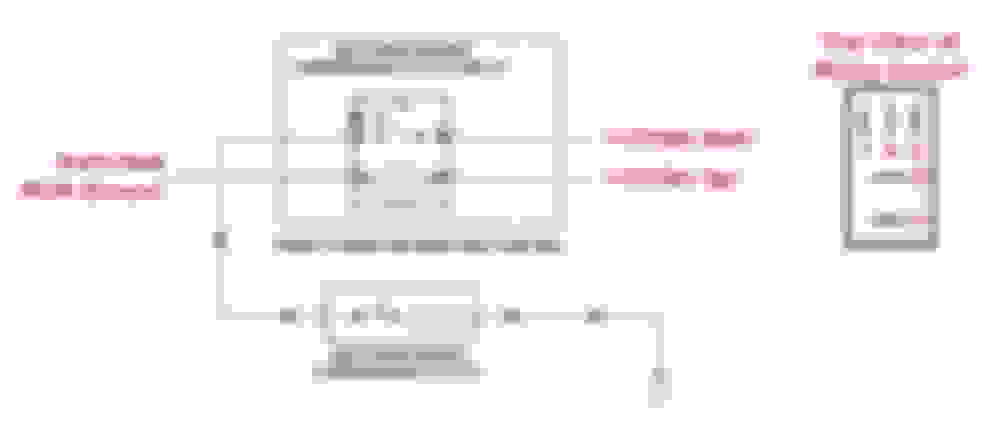
Next follow the three lines from the DCCV back to the heater core. They run along the inner fender, on the US passenger's side. The small line at the top is the supply for the left side of the cabin. The small middle line is the supply for the right side. The large line at the bottom is the common return. The arrangement of the lines is the same for both LHD and RHD cars. In this excerpt from a Jaguar training manual, the 'driver' and 'passenger' designations apply to LHD cars:
With manual LO selected since engine start, both valves in the DCCV should have remained closed if working properly. No coolant should be flowing in those lines. The trapped coolant may warm slightly due to the close proximity of the exhaust manifold. However, and this is VERY important, all three lines MUST be roughly the same temperature AND much cooler than the 200F coolant waiting patiently on the other side of the DCCV.
Here's an example from my car, recorded on a 70F day. The engine was cool from sitting overnight. After running at idle until the dash gauge was centered, the three lines all read approximately 75F, only a slight increase over ambient.
Remember, it's important to run this test only after warming a cold engine while parked. If you try this after a normal drive, there will be too much radiant heat under the hood. Even if both DCCV valves are properly closed, the heater lines will be too warm to see much difference from the 200F coolant.
After confirming both valves within the DCCV have remained closed, the next step is to check the line temperatures when open. Select manual HI and both valves should relax to the full open position. The two smaller lines should quickly shoot up to approximately 200F as hot coolant starts flowing to the heater core. The larger return line may slowly change temperature, but this value is not important. Please be aware once you close the valves again by selecting manual LO, hot coolant will remain trapped in those lines, even if not flowing. It will take some time for the lines to cool off again, so don't misinterpret that by itself as a DCCV that has not closed. To correctly diagnose a bad DCCV not fully closing, you must make sure the heater supply lines are cooler than the 200F coolant BEFORE commanding the valves open.
If your DCCV has responded properly, you're done with this section. Return to the symptom list at the end of the introduction (Post #1 above) to continue troubleshooting.
If the DCCV has failed on a 2003+ S-Type, be sure to visit this website for details of possible damage to the ACCM and a suggested upgrade:
If the DCCV has not been fully closing, at least some hot coolant is reaching the heater core and dumping heat into the cabin. In that case, the next step is to determine if the valves in the DCCV won't physically close, or are not receiving the proper electrical command. In the first step above, we had checked the fuse. If that checks good, remove the connector from the DCCV. You will be working by Braille. The connector has a red lock which you must slide to release.
In my not-so-humble opinion, if the troubleshooting has brought you to this point, and you've not skipped any steps, you're almost guaranteed to need a new DCCV. The electrical checks in the next paragraph are just a 'Hail Mary' (for unlikely wiring faults) as you prepare to change the DCCV.
With the engine on and manual LO selected, check the harness connector for 12VDC at the center pin. This is the power supply coming from the fuse you previously checked. With a constant power supply, the ACCM controls the DCCV by modulating a ground for each side. With LO still selected, an ohmmeter should indicate a good connection to ground at the two outer pins. If the electrical checks are good, but the DCCV was still sending hot coolant to either side of the heater, you've got a bad DCCV that has not properly closed when commanded.
Courtesy of JaguarClimateControl.com, here's a more involved test that will tell you basically the same thing:
If you replace the DCCV, repeat either test above. The DCCV has a very high failure rate and there's no guarantee a new one will be good.
After any repairs, return to the symptom list at the end of the introduction (Post #1 above) to continue troubleshooting.
Remember, if you'd like troubleshooting assistance, please start a new thread instead of replying to this one. Please limit replies in this thread to general troubleshooting concepts, additional tips, lessons learned, etc.
Verify Proper Operation of the DCCV - Everbody Do This Test
Please start with the introduction (Post #1 above). After that, no matter the symptoms, everybody gets to do the steps in this post:
Verify proper operation of the DCCV
The DCCV can be a problem child. Before doing anything else, let's make sure the two valves in the DCCV operate properly. If these valves stick open, even partially, hot coolant will reach the heater core and heat will be dumped into the cabin. If stuck closed, no heat will be available.
Courtesy of forum member Caveforce, here's an extreme example showing a clogged DCCV:
Remember, these valves are spring-loaded open, and a steady 12V DC input is required to close them. Start by checking the DCCV fuse.
For a pre-facelift car (1999-2002), check fuse #1 at the Front Power Distribution Box under the hood:
For a post-facelift car (2003+), check fuse F32 at the Front Power Distribution Box:
We will run some additional electrical checks later. But for now, let's check to see if the DCCV is sticking open, even if commanded closed. Two methods are available to test if both valves are fully closing. The second method is preferred.
For both methods, make sure the coolant level is correct. Especially on V6 models, low coolant can cause a reduction in flow to the heater. If a DCCV has stuck open, this can give a misleading indication that it has closed.
1) The quick and dirty way is to compare duct and exterior air temperatures. The interior must not be warm from the sun. Park in the shade for several hours with the windows open or run this test early in the morning. Select manual LO and medium fan speed. Press the A/C button once to turn off the compressor. The light in the A/C button should be off. Having the AC compressor off makes sure the air flowing through the ducts will not be cooled for this test. Go for a test drive and fully warm up the engine. While driving, take note of the temperature reading at the center duct on each side. Let the thermometer acclimate for several minutes in each position. If your exterior temperature display (on the control panel) seems accurate, you can use that as a reference.
If the duct temperature was warmer than exterior air, at least one valve was letting hot coolant reach the heater core and must be corrected. For best results, take these temperature readings during a test drive. This helps reduce the effect of hot air from the engine reaching the cabin air inlet at the base of the windshield. If unsure about the results of this test, do the more accurate method in the next step, which requires the use of an infrared thermometer.
Here are my test results immediately after a test drive. The center dash vent showed 72F on a 69F day, so I'd call that good. I had also confirmed the valves were closed with the next test, so I know this was a good indication:
2) Let the engine sit overnight so it is fully cold. Start the engine and immediately select manual LO. Do not change this setting until instructed. Bring the engine up to normal operating temperature (dash gauge centered) while parked, running at idle speed only with the hood open. These conditions are very important, to minimize radiant heat in the engine compartment. Expect about 8 minutes for the engine to fully warm at idle. With your infrared thermometer, make sure the radiator inlet (upper hose) measures approximately 200F.
With the engine fully warm, rev the engine at approximately 1500 RPM for two minutes. Coolant flow to the heater is marginal at idle, especially on V6 models. This step makes sure the coolant flow has enough oomph to force past a DCCV that has not fully closed.
Next follow the three lines from the DCCV back to the heater core. They run along the inner fender, on the US passenger's side. The small line at the top is the supply for the left side of the cabin. The small middle line is the supply for the right side. The large line at the bottom is the common return. The arrangement of the lines is the same for both LHD and RHD cars. In this excerpt from a Jaguar training manual, the 'driver' and 'passenger' designations apply to LHD cars:
With manual LO selected since engine start, both valves in the DCCV should have remained closed if working properly. No coolant should be flowing in those lines. The trapped coolant may warm slightly due to the close proximity of the exhaust manifold. However, and this is VERY important, all three lines MUST be roughly the same temperature AND much cooler than the 200F coolant waiting patiently on the other side of the DCCV.
Here's an example from my car, recorded on a 70F day. The engine was cool from sitting overnight. After running at idle until the dash gauge was centered, the three lines all read approximately 75F, only a slight increase over ambient.
Remember, it's important to run this test only after warming a cold engine while parked. If you try this after a normal drive, there will be too much radiant heat under the hood. Even if both DCCV valves are properly closed, the heater lines will be too warm to see much difference from the 200F coolant.
After confirming both valves within the DCCV have remained closed, the next step is to check the line temperatures when open. Select manual HI and both valves should relax to the full open position. The two smaller lines should quickly shoot up to approximately 200F as hot coolant starts flowing to the heater core. The larger return line may slowly change temperature, but this value is not important. Please be aware once you close the valves again by selecting manual LO, hot coolant will remain trapped in those lines, even if not flowing. It will take some time for the lines to cool off again, so don't misinterpret that by itself as a DCCV that has not closed. To correctly diagnose a bad DCCV not fully closing, you must make sure the heater supply lines are cooler than the 200F coolant BEFORE commanding the valves open.
If your DCCV has responded properly, you're done with this section. Return to the symptom list at the end of the introduction (Post #1 above) to continue troubleshooting.
If the DCCV has failed on a 2003+ S-Type, be sure to visit this website for details of possible damage to the ACCM and a suggested upgrade:
If the DCCV has not been fully closing, at least some hot coolant is reaching the heater core and dumping heat into the cabin. In that case, the next step is to determine if the valves in the DCCV won't physically close, or are not receiving the proper electrical command. In the first step above, we had checked the fuse. If that checks good, remove the connector from the DCCV. You will be working by Braille. The connector has a red lock which you must slide to release.
In my not-so-humble opinion, if the troubleshooting has brought you to this point, and you've not skipped any steps, you're almost guaranteed to need a new DCCV. The electrical checks in the next paragraph are just a 'Hail Mary' (for unlikely wiring faults) as you prepare to change the DCCV.
With the engine on and manual LO selected, check the harness connector for 12VDC at the center pin. This is the power supply coming from the fuse you previously checked. With a constant power supply, the ACCM controls the DCCV by modulating a ground for each side. With LO still selected, an ohmmeter should indicate a good connection to ground at the two outer pins. If the electrical checks are good, but the DCCV was still sending hot coolant to either side of the heater, you've got a bad DCCV that has not properly closed when commanded.
Courtesy of JaguarClimateControl.com, here's a more involved test that will tell you basically the same thing:
If you replace the DCCV, repeat either test above. The DCCV has a very high failure rate and there's no guarantee a new one will be good.
After any repairs, return to the symptom list at the end of the introduction (Post #1 above) to continue troubleshooting.
Remember, if you'd like troubleshooting assistance, please start a new thread instead of replying to this one. Please limit replies in this thread to general troubleshooting concepts, additional tips, lessons learned, etc.
Please start with the introduction (Post #1 above) and then verify proper operation of the DCCV (Post #2 above). The steps in this post are only for the following condition:
Inadequate/erratic heating or cooling in automatic mode. Okay in manual.
This scenario is a common one. Since manual mode works, we are only going to look at the automatic control system. Keep track of the fan speed for a big clue to system behavior. In automatic mode, as the cabin reaches the requested temperature, the fan will slow down. If not, this indicates a problem.
1) Check the external temperature reading on the control panel. The value displayed should be within a few degrees of the actual temperature. If the reading is off by much, the controller may not request much heating or cooling in automatic mode.
I have personal experience with this one. When I take my '02 through the carwash, the sensor (or some connector) gets wet and the display temporarily reads about 20F low. In automatic mode, the AC output is reduced dramatically. After about 5 minutes of driving, everything dries out and the AC roars back to life. If you don't normally have the external temperature displayed and the sensor had permanently failed, it would be easy to miss a fault like that.
2) Check the operation of the sunlight sensor. On a sunny day, note the fan speed and center duct temperature in automatic mode. Cover the sensor to block all sunlight and repeat the test. If the sensor is operating properly, the fan speed (and possibly the duct temperature) should respond to warm the cabin slightly to compensate for the perceived lack of sunlight. The response is slow and easy to miss, maybe a few degrees of difference at most. I haven't figured out a reliable method to compare the two sides relative to each other.
3) Check the operation of the cabin temperature sensor. With the engine running, manually select the fan speed to high. Hold a piece of tissue over the sensor grill, above the ignition key. If the suction is not strong enough to hold the tissue, expect to find the duct clogged with dust. Access is very difficult to replace the sensor, but the grill can be pried off for a visual inspection. Vacuum the duct as needed and repeat the tissue test.
After vacuuming, clean the sensor with electronic spray cleaner. A film can develop on the sensor, preventing an accurate reading. Switch back to automatic mode and spray the sensor again. The fan speed (and possibly the duct temperature) should respond to compensate for the cold spray.
Another rough test of the cabin temperature sensor is to observe the recirculation light with the AC running in automatic mode. On a cooler day or at night (75F or so), select 72F in automatic mode and drive long enough for the cabin to reach this temperature. As long as some cooling is available, this should be possible. Remember, slowing of the fan is your clue that the system is close to the requested temperature. Still in auto, select 66F and the recirculation light should illuminate. From my experimentation, any time the setting is at least 5F cooler than the actual cabin temperature, recirculation mode will automatically be engaged for the quickest cooling action. If the fan and recirculation light behave this way, the cabin temperature sensor is probably okay.
4) Check the two duct discharge temperature sensors. Start with 72F selected for both sides in automatic mode. If one side has warm air and the other cool, and you've already confirmed the DCCV can close properly (See post #2 above), one of these sensors is the most likely culprit. Adjust the temperature up on the warm side only and see if the fan speed slows down. If so, the sensor for that side is reading high and should be replaced.
If no change, adjust that side back to 72F. Adjust the temperature setting down on the cool side only. If the fan speed slows down, that sensor was reading low and should be replaced.
For verification, consult your wiring diagrams here, courtesy of Gus, and scroll to section 6.1:
Let the car sit for several hours, preferably in the shade, to let all duct temperatures equalize. Remove the ACCM (control panel). From the connector, read the resistance values for the two duct discharge temperature sensors. Also note the evaporator discharge sensor is the same part number, so measure that while you're in there. If the three sensors are at the same approximate temperature, the resistance values should be very similar. You're not worried about the specific value so much, but rather how close they are to each other. If one sensor is much different from the others, it's probably bad. If you'd prefer not to remove the panel, you can read the sensors individually after removal. The MotorCraft part number for these 3 sensors is YH1504.
At 77F, the sensor is supposed to read 30 kilohms. Below are approximate values for other temperatures. Please note this chart is based on a single sample only, so may not be fully accurate:
35F 79.5 kilohms
40F 75.0 kilohms
45F 66.0 kilohms
50F 57.5 kilohms
55F 51.0 kilohms
60F 44.0 kilohms
65F 39.3 kilohms
70F 34.3 kilohms
75F 30.8 kilohms
77F 30.0 kilohms
80F 27.4 kilohms
85F 24.3 kilohms
90F 21.6 kilohms
95F 19.2 kilohms
When the sensors are installed, all you see is the rectangular portion for the electrical connector. The long probe sticks into the duct. For removal, undo the electrical connector first, as there's only room to reach with one hand. Once the connector is off, then you can unsnap the sensor from the hole in the duct. Note the clips that snap into the hole in the duct.:
If you stand on your head in the left footwell, you can see two of the sensors above the transmission tunnel. The one closer to the firewall is the evaporator temperature sensor, used in both automatic and manual modes. The other sensor is for the left duct discharge temperature, used only in automatic mode:
The right duct discharge sensor (not shown) is all by itself on the other side, close to the dash in a mirror image of the left side. You've got to remove a trim panel under the glove box to see it.
The sensor locations can also be seen at the following link. Note the three sensors are all mistakenly called 'evaporator temperature sensors':
5) If all of the above tests check good, go back and measure the resistance of the cabin temperature sensor you cleaned in step 3. This is easy to do while you have the control panel removed for the step above. Although this sensor is a different part number, the resistance values are the same as listed in the previous chart for the three YH1504 sensors.
After any repairs, return to the symptom list at the end of the introduction (Post #1 above) to continue troubleshooting.
Remember, if you'd like troubleshooting assistance, please start a new thread instead of replying to this one. Please limit replies in this thread to general troubleshooting concepts, additional tips, lessons learned, etc.
Insufficient Cooling from the AC system in Automatic or Manual Mode.
Please start with the introduction (Post #1 above) and then verify proper operation of the DCCV (Post #2 above). The steps in this post are only for the following condition:
Insufficient cooling from the AC system in automatic or manual mode. Duct temperature lower than exterior air.
Remember, in post #2 above, we've already eliminated any faults letting the heater core dump unwanted heat into the cabin. It is VERY important to complete the steps in post #2 before starting here.
Now we will confirm the underhood portion of the AC system is "making cold" in sufficient volume. In this section, we are only looking at AC faults that are present in automatic or manual. If you only have problems in auto, refer to post #3 above.
This part is a bit trickier. Unless you're an AC professional with lots of experience, some of this is a judgement call. We can rule out or correct some obvious faults and then retest, but that's about it.
The rest of this section is based on the premise of SOME cooling coming from the AC system, meaning the center duct temperature is cooler than the outside air. If NO cooling is present, see post #5 below. As a general guideline, you should see approximately 38F at speeds over 30 MPH. Below that speed, it's okay for AC output to creep up to approximately 45F on hotter (95F+) days.
For an AC system to "make cold" at the evaporator in sufficient quantity, it must have four basic things, in no particular order:
1) Good airflow through the evaporator.
2) Good airflow through through the condenser (in front of the radiator) for proper heat transfer.
3) Good performance from the compressor
4) The correct amount of refrigerant in the system
A partial loss of any of these basic requirements is a common problem, and will cause the overall performance to drop off. You'll still get some cooling, but not enough. Be careful here, because it's very easy to misdiagnose the root cause of limited cooling.
A) I've listed evaporator airflow first, because it's easy to rule out a problem here. Inspect the cabin air filter, at the base of the windshield on the left side, and replace as needed. If this filter is restricted, cooling from the evaporator will be reduced.
B) A problem with condenser airflow is also very easy to eliminate. Above 30 MPH or so, there's plenty of ram airflow through the condenser. At lower speeds and when stationary, an electric fan handles the air movement duties. When watching under the hood and the AC compressor is commanded to run, you should see the fan run, too. If not, that's one problem that must be corrected before proceeding.
If the fan is running, the next step is to confirm good airflow through the condenser. It's possible for the condenser fins to become blocked with bugs and other debris. Another possibility is the electric fan motor may have worn brushes and is not spinning at full speed. With the AC on so the fan is running, hold a rag in front of the grill. If the fan is drawing an adequate volume through the condenser, the rag will be held tightly in place. Although this test seems like a no-brainer, don't skip it because good airflow is a very important part of the cooling equation.
C) The next thing to check is adequate performance from the compressor. As a compressor ages, the pumping ability drops. Hook up your service manifold set and see if the compressor can draw the low side down to approximately 39PSI, which corresponds to 34F at the evaporator.
Please note I have not included any expected high side values. Pressure readings on the high side have many variables, specifically temperature, airflow, and refrigerant quantity. I don't put a lot of stock in the gauge readings for the high side. For example, the AC pressure sensor sends a signal to the PCM, which controls the electric fan to hold the high side pressure within the desired range. What's so tricky about that? Well, the 'desired range' changes based on cooling demand, ambient temperature, and who knows what else, so there's no one good answer.
D) Looking ahead, we will investigate some possible faults that can affect the compressor, but it's not time for that yet. I've saved the most likely problem for now: Improper refrigerant quantity. By "improper", I mean "too low". This is a very common problem. No matter how well-sealed the system may seem, refrigerant will escape. Those tiny R134a molecules are slippery little buggers with no sense of loyalty. Given the slightest opportunity to break free, those little Houdinis will make a run for it. Wily as they are, they may slip out one at a time over a long period to avoid attracting attention. If you insist on stating your AC system is 100% sealed and doesn't leak, my only response (other than furious bouts of laughter) will be that you are 100% wrong.
Somewhere around this point, I can expect to be asked about determining refrigerant quantity based on pressure readings. "Oh look, this chart on the internet says you can do it, so it must be true!" Full stop! Pressure gauge readings can NOT accurately determine refrigerant quantity. The gauge set can show if the system is very low, practically empty, but that's about it.
"Thanks, I understand, but what readings should I see with the proper quantity?" Excuse me for a moment while I check my birth certificate. Hmm, wasn't born yesterday, just like I thought. I'm not falling for a rephrased version of the same question.
"Got it, I understand now that you can't determine refrigerant quantity from a pressure gauge. By the way, I bought one of those top-off kits with a gauge on it. What pressure should I see when the system is full?" Pardon me while I scream...
Let me repeat myself: Pressure gauge readings can NOT accurately determine refrigerant quantity. Unlike normal compressed gasses, refrigerant is weird stuff and you must think differently to understand it. Here's a little example to help illustrate this important distinction. Imagine you've got a tank with a pressure gauge. Using a 'normal' gas like compressed air (for filling tires, etc.), the more volume you put in the tank, the higher the pressure rises. This is simple and easy to understand. The pressure changes proportionally with the volume of compressed air.
Now we're going to fill a similar tank with refrigerant. Pump a tiny amount into an empty tank, and the refrigerant will expand as a gas to fill available space. As more refrigerant is added, here's where it gets weird. The stuff liquifies and collects at the bottom of the tank, leaving some gas at the top, all at the same pressure. Once the temperature stabilizes, the pressure never rises no matter how much is added, until the tank is completely full with liquid. With increasing volume, instead of causing a pressure rise, you simply get a higher liquid level and less gas. Propane behaves in a very similar fashion. You can buy a worthless pressure gauge for your propane BBQ, but the pressure is constant until the tank is nearly depleted and all liquid has turned back to gas, at which point the tank is about to run dry. Here's an illustration showing two tanks at the same temperature holding vastly different quantities of refrigerant, but the pressure is the same:
Hopefully this will put the pressure/quantity correlation to rest. Some guys insist they can fill to a certain pressure and don't have to measure quantity. Those are typically pros who would hurt themselves laughing at my guide. With so many variables, especially the fan acting on the high side, correlating pressure to volume is beyond the capabilities of us mere mortals and I don't suggest doing so.
How can a poor guy determine refrigerant quantity? The official party line is to do a full vacuum evacuation and refill. Starting from zero, you can accurately measure the amount added and be positive about the quantity. This is the preferred method because it is guaranteed to be correct.
Is there a lazy man's method we can try, something with a good chance of success? Funny you should ask. Yes, it's perfectly acceptable to add several ounces and see if the cooling improves. I call this an 'investigative top-off'. Please be aware this is NOT an official Jaguar procedure, and I've caught some flak over it. You decide if you want to try it. I've had about an 80% success rate on various vehicles over the years. If it doesn't work, you won't damage anything other than your ego. At worst, you will waste a little bit of time and refrigerant.
In my overly inflated opinion, low refrigerant quantity is the most likely cause of inadequate AC performance. There are plenty of other possibilities, but this one is so common, it's worth trying an investigative top-off before delving too deep elsewhere. This procedure is only appropriate if ALL of the following conditions are present:
1) The system must be "making cold" to some extent. If not, the fault is more serious than a little loss of refrigerant.
2) Several years must have elapsed since the last top-off or full vacuum evacuation and recharge. It's perfectly normal for refrigerant to leak down a little over three or four years. Any less time than that indicates a bigger leak in need of repair, or some other problem.
3) You must have the willpower to stop if adding several ounces doesn't help. This one is very important for success. The actual top-off process is very simple. Hook up your service gauge set and add about three ounces, approximately one quarter of a small can. Go for a test drive and see if the cooling improves.
If better, but still not optimal, try adding another three ounces. The trick is to stop once no further improvement occurs. I've got to warn you, stopping is tough. Often you'll see a decent improvement with the first shot. You'll be so excited, you could cut glass with your nipples. You then tried a second shot, and maybe still had some improvement, but usually not as big as the first.
This means you're near the correct level, perhaps even slightly over, but since that first shot worked so well, it's tempting to overdo it. "Why, if 3 ounces was good the first and second times, I bet 5 would be even better this time!" Next thing you know, the system is severely overfilled and the performance drops off again. This is where you start cursing me for suggesting this method, since it obviously doesn't work. Ah, but Grasshopper, it did work, only you got carried away and overdid it. So if you want to take this pebble from my hand, make sure you are prepared to stop when no further improvement is observed.
Also, be aware your AC system may have another fault in addition to low refrigerant. If the improvement stops, but performance is still subpar, it's time to investigate other possible causes.
If you find a full evacuation and recharge is necessary, there's a service bulletin you should consider. Jaguar issued instructions to reposition the bypass valve piston and spring inside the compressor. See the introduction section (Post #1 above) for more details of this valve. This modification disables the compressor's pressure-sensing variable output feature, and runs the compressor at maximum output. I have not done modification myself, as my AC system has generally performed very well. For all I know, it was done before I bought the car. Supposedly this can be done from underneath the vehicle without removing the compressor. You must completely depressurize the system, meaning a full evacuation and recharge must then be performed. Once again, I've no personal experience with this simple modification, but other forum members swear by it.
The directions aren't very clear until you read them a few times. You are removing a piston and spring under an access plate on the aft side of the compressor. Originally, the piston was spring-loaded towards the plate. For this modifiction, you are inserting the piston first (not flipped, same orientation), and then putting the spring closest to the plate. This forces the piston away from the plate and disables the variable output feature. This link (from the X-Type section of the forum) shows the plate, piston, and spring on the same type of compressor:
I'll look into this modification next time I have to do an evacuation and recharge. If your AC had been performing well until recently, this likely isn't your problem. This modification is more appropriate if performance has been okay but never stellar, especially at lower speeds.
Curiously, this same type of compressor (Visteon brand) is used on many vehicles of this vintage, particularily Fords, Saturns, and Volvos. If you search online, you can find a lot of information about this valve. However, as best I can determine, Jaguar was the only vehicle manufacturer that issued instructions to disable the variable output feature.
Almost there, just a few more things to investigate for an underperforming AC system.
At idle, watch the face of the compressor pulley for a big troubleshooting clue. The main body of the pulley, where the belt rides, always spins with the engine. The pulley's face is connected to the compressor shaft. When the compressor is commanded off, the pulley face is stationary, even though the pulley is still spinning. When the compressor is commanded to run, a beefy electromagnet (called the compressor clutch coil) clamps the pulley face to the spinning part of the pulley, and the compressor shaft spins, too. By watching the pulley face, we can generally tell if the compressor has been commanded to run. Here's a good video showing a bench test of a compressor clutch. Although it's a different brand of compressor, this shows how the electric clutch works:
One gotcha to consider: You may find other troubleshooting guides that talk about compressor cycle times. The idea is by observing the clutch action, you can get a good idea of compressor performance, refrigerant quantity, etc. Great stuff, but it doesn't really apply to the Jaguar system. Remember that variable output feature on the Visteon compressor? This feature causes the compressor to cycle less and run for longer periods of time, so any such troubleshooting is not accurate. Don't fall for that trap. If by chance you do find some guide that says it applies to the Jaguar S-Type, you'd have to know if your car has had the compressor modification.
1) If the compressor is running, and the refrigerant level is correct (see the two methods above), but performance is still low, it's possible the clutch is slipping. This is more common than you may think. I've found this fault on my S-Type and several other vehicles. In my case, the compressor control relay had arcing at the contacts, which reduced the current flow and clamping force at the clutch. The AC still operated, but the performance was only so-so.
Swap the relay with a known-good one from another position and see if the cooling improves. If so, the original relay was bad. For this test, I used the fog lamp relay, so make sure the lights work before swapping to confirm the donor relay is good. These relays are located under the hood, in the Front Power Distribution Box. On all years, the AC compressor clutch control is relay #8.
On early models, the fog lamp relay is #7:
On late models, the fog lamp relay is #11:
2) The next step is to mark the compressor clutch with two paint marks to check for slippage. This is a compressor from a different vehicle with a V-belt drive, but the idea is the same.
Remove relay #8 and connect a jumper between socket terminals #3 and #5, as shown below:
The jumper forces the compressor to run full-time, even while the starter is engaged. Start the engine, idle for 5 seconds maximum, and shut off the engine. Do not exceed 5 seconds run time as all system protection has been overridden. With the engine off, crawl back underneath and compare the paint marks. Anything more than a 1/4" shift indicates the clutch has slipped.
Keep in mind slippage could be caused by a mechanical problem such as a worn clutch, excessive air gap, or mechanical dragging inside the compressor. The problem could also be an external electrical problem limiting current and reducing the clamping force. In a previous step, we did some swapping to rule out a bad relay. If the paint marks show evidence of slippage, and the control relay was already swapped, further electrical troubleshooting is warranted before condemning the clutch. For example, a damaged wire or corroded connector could mimic a worn clutch.
On other vehicles requiring a new clutch coil, I've found I could get an entire replacement compressor with clutch for little more than just the clutch, so shop around.
3) Does the AC seem to work okay for the first few minutes and then slowly put out warmer air? In addition, have you noticed a large puddle of water forming some time after shutting off the engine? Some minor ice accumulation on the evaporator is normal, but an excess actually becomes an insulator and reduces cooling. In extreme cases, airflow is completely blocked and the automatic mode revs up the fan, unaware the airflow isn't actually increasing. If you suspect icing at the evaporator, the first step is to make sure the refrigerant quantity is correct (see the two methods above). After that, investigate the evaporator temperature sensor. A bad sensor won't shut off the compressor as the evaporator approaches the freezing point, which lets ice accumulate. See Auto Mode Faults (Post #3 above) for details of how to check the resistance of the evaporator temperature sensor. Remember, this is the same part as the two duct discharge temperature sensors, so you've got those for comparison.
4) The next item to consider for marginal cooling is the AC pressure sensor, installed on the high pressure side. This sensor provides an input to the PCM for operation of the compressor clutch and the electric fan. If the high side pressure rises above 420 PSI, the PCM shuts off the compressor to prevent damage. In the event of a major leak, and pressure drops below a minimum safe level, the PCM will not engage the compressor clutch. I'm kinda fuzzy on the best way to troubleshoot this sensor. The AC pressure sensor seems to be very reliable. It's not likely to cause insufficient cooling, but if bad, it has a check valve and can be replaced without discharging the entire system.
5) After all of the above steps, you're probably looking at a compressor or thermal expansion valve for instances of marginal cooling. Based on the reliability of the thermal expansion valve, I'd lean towards the compressor. If you suspect the compressor, I'd highly suggest first trying the modification of the bypass valve spring as detailed above.
One last gotcha to consider. Look through other threads, and you may read how a new (insert name of expensive part) fixed an AC problem. If replacement required a full evacuation and recharge, the primary problem may have been a low refrigerant charge, not an actual component fault. Few people bother with a full recharge when troubleshooting, but be aware low refrigerant can mimic many component faults. Before convincing myself that a compressor was bad, for example, I'd highly recommend gambling on a full evacuation and recharge first to be sure.
After any repairs, return to the symptom list at the end of the introduction (Post #1 above) to continue troubleshooting.
Remember, if you'd like troubleshooting assistance, please start a new thread instead of replying to this one. Please limit replies in this thread to general troubleshooting concepts, additional tips, lessons learned, etc.
No Cooling from the AC System in Automatic or Manual Mode.
Please start with the introduction (Post #1 above) and then verify proper operation of the DCCV (Post #2 above). The steps in this post are only for the following condition:
No cooling from the AC system in automatic or manual mode. Duct temperature equal to or higher than exterior air.
Remember, in post #2 above, we've already eliminated any faults letting the heater core dump unwanted heat into the cabin. Complete the steps in post #2 before starting this section, or the results here may be skewed.
This section is for NO cooling, meaning the duct temperature is equal to or higher than exterior air. If you have SOME cooling, see post #4 above.
We will look at three main scenarios for no cooling:
A) The controller has sent the command for the compressor clutch to engage, but there is no response. This is most likely a fault in the clutch coil or the PCM output circuit.
B) The controller is not commanding the compressor clutch to engage. This is most likely a controller input problem.
C) The clutch has engaged and the compressor shaft is spinning, but no cold air comes from the ducts. This is most likely a mechanical fault within the AC system.
Start by manually selecting LO on the control panel and observing the compressor clutch. See post #4 above for details of the compressor clutch operation and how to tell when it is engaged.
1) If the compressor clutch does not engage:
A) Check the fuses. One fuse provides direct battery power to the clutch coil. A second fuse provides switched ignition power to operate the clutch control relay. Both fuses must be good for the clutch to engage.
On an early model, check fuses #1 and #11 at the Front Power Distribution Box.
On a later model, check fuses #F32 and #F38 at the Front Power Distribution Box.
B) Swap the clutch control relay with a known-good one from another position and see if the clutch engages. If so, the original relay was bad. The fog lamp relay is the same part, so make sure the lights work before swapping to confirm the donor relay is good. These relays are located under the hood, in the Front Power Distribution Box. On all years, the AC compressor clutch control is relay #8.
On early models, the fog lamp relay is #7:
On late models, the fog lamp relay is #11:
C) If the fuses are good and swapping relays didn't help, the next step is to check if the clutch coil will energize. Keep the ignition switch off for this test. Remove relay #8 and connect a jumper between socket terminals #3 and #5, as shown below:
The jumper supplies direct battery power to energize the clutch coil, bypassing all control inputs. You should hear an audible click as the clutch engages.
If there is no click, go to step E below.
D) If you heard a click, the next step is to mark the compressor clutch with two paint marks to check for slippage. This is a compressor from a different vehicle with a V-belt drive, but the idea is the same.
Keep the jumper installed between socket terminals #3 and #5, as above. The jumper forces the compressor to run full-time, even while the starter is engaged. Start the engine, idle for 5 seconds maximum, and shut off the engine. Do not exceed 5 seconds run time as all system protection has been overridden. With the engine off, crawl back underneath and compare the paint marks. Anything more than a 1/4" shift indicates the clutch has slipped.
Keep in mind slippage could be caused by a mechanical problem such as a worn clutch, excessive air gap, or mechanical dragging inside the compressor. The problem could also be an external electrical problem limiting current and reducing the clamping force. In a previous step, we did some swapping to rule out a bad relay. If the paint marks show evidence of slippage, and the control relay was already swapped, further electrical troubleshooting is warranted before condemning the clutch. For example, a damaged wire or corroded connector could mimic a worn clutch.
For an optional test, keep the ignition switch off and connect an ammeter between relay sockets 3 and 5. A clutch coil in good condition will draw approximately 2.8 amps.
E) If you heard no click with the jumper installed (Step C), remove the jumper and check for continuity between socket 5 and ground. Expect to see approximately 1.4 ohms with a good clutch coil. By testing from this location, we are also including all wiring from the relay socket to the compressor and on to ground.
If resistance between socket 5 and ground is far out of range (including no continuity), crawl underneath and remove the connector from the compressor. Measure the continuity between the two terminals on the compressor. If now good, the wiring harness is likely damaged. If resistance is still out of range, the compressor clutch itself has failed electrically. Be aware the clutch has a thermal switch that will open if the compressor overheats. Once the compressor cools, the switch should automatically close. If the test fails, let the compressor cool if necessary and repeat.
On other vehicles requiring a new clutch coil, I've found I could get an entire replacement compressor with clutch for little more than just the clutch, so shop around.
2) In the tests above, if the compressor clutch engages when the relay is jumpered, but the clutch still doesn't engage with a known-good relay installed, it's time to look at controller input faults. Any of the following conditions will inhibit the command for the compressor to run. All items, except for the obvious ones, are followed by a brief suggestion for troubleshooting. One major catch is you have no surefire way to know which condition(s) is inhibiting the command. You will have to run through a process of elimination:
A) Engine starter engaged - Obvious
B) Wide open throttle - More obvious
C) Over 5882 RPM - Obvious yet again
D) Under 400 RPM (V8) or 450 RPM (V6) - Not getting any less obvious
F) Power steering pressure high (compressor disabled for 5 seconds only) - Make sure steering wheel is at neutral position. This is
not a likely fault, because it is canceled after 5 seconds.
G) Exterior temperature below 27F - Check display on control panel.
H) Evaporator discharge temperature below 34F - Check sensor as detailed in post #3 (Auto Mode Faults) above. Compare with the two duct discharge temperature sensors for best results.
I) High side pressure above 420 PSI - Not very likely, unless the AC pressure sensor has failed and is always indicating extremely high.
J) Low refrigerant quantity - The AC pressure sensor has detected low pressure. On a 75F day for example, the low limit is approximately 60 PSI. Remember from the introduction (Post #1 above), the pressure can't accurately indicate the actual refrigerant quantity. When the quantity is very low, however, the pressure does begin to drop off. This low limit is only meant to prevent compressor damage, not indicate adequate quantity. With the engine off, check the pressure with a gauge set. The high and low sides should be equalized and read the same. If pressure is low at rest, the system has a major leak. Repair and do a full evacuation and recharge. If actual pressure is above 60 PSI, replace the AC pressure sensor.
3) If the compressor clutch does engage, but there's still no cooling:
A) The AC pressure sensor has detected enough refrigerant to let the compressor run. This does NOT guarantee the quantity is adequate for normal operation. It only means the system is not completely empty.
B) Check for a compressor clutch that is severely slipping. From the 'compressor clutch does not engage' section above, do the steps with the paint marks and jumper at relay #8. If the clutch was slipping, continue with that troubleshooting.
C) If the compressor clutch was not slipping, check the compressor performance. Hook up your service manifold set. Reinstall the relay and start the engine. See if the compressor can draw the low side down to approximately 39PSI, which corresponds to 34F at the evaporator.
If so, the compressor and thermal expansion valve are probably good. Do a full evacuation and recharge of the AC system and check for improvement.
If no improvement, the compressor has seen better days or the thermal expansion valve is possibly stuck open.
One last gotcha to consider. Read through other threads, and you may find how a new (insert name of expensive part) fixed an AC problem. If replacement required a full evacuation and recharge, the primary problem may have been a low refrigerant charge, not an actual component fault. Few people bother with a full recharge when troubleshooting, but be aware low refrigerant can mimic many component faults. Before convincing myself that a compressor was bad, for example, I'd highly recommend gambling on a full evacuation and recharge first to be sure.
After any repairs, return to the symptom list at the end of the introduction (Post #1 above) to continue troubleshooting.
Remember, if you'd like troubleshooting assistance, please start a new thread instead of replying to this one. Please limit replies in this thread to general troubleshooting concepts, additional tips, lessons learned, etc.
Please start with the introduction (Post #1 above) and then verify proper operation of the DCCV (Post #2 above). The steps in this post are only for the following condition:
No heat in automatic or manual mode.
Remember, in post #2 above, we've already eliminated any faults with the DCCV. It is VERY important to complete the steps in post #2 before starting here.
1) With the engine cold, make sure the coolant level is correct at the reservoir.
2) Compare heater operation at idle and at approximately 2000 RPM.
A) On V6 models, the heater may perform poorly at low engine RPM, but is fine at higher engine speeds. This is caused by air in the heater lines. You can purge the lines per the service manual, but normal driving with the correct coolant level will usually force air from the heater lines. If not, you can always purge the lines per the manual.
B) On V8 models, check the operation of the auxiliary coolant pump. This pump is designed to supplement coolant flow during low RPM operation. With the engine at idle, you should be able to feel the pump running. The fuse is the same as for the DCCV, previously checked in post #2 above.
3) With an infrared thermometer, make sure the radiator inlet (upper hose) measures approximately 200F. If the coolant is not warm enough, heater performance will be poor. Be aware the dashboard temperature gauge is deliberately misleading, as detailed at the following link, so don't rely on it. This is from the XK forum, but the general principle is the same on the S-Type:
After any repairs, return to the symptom list at the end of the introduction (Post #1 above) to continue troubleshooting.
Remember, if you'd like troubleshooting assistance, please start a new thread instead of replying to this one. Please limit replies in this thread to general troubleshooting concepts, additional tips, lessons learned, etc.
WOW!! Although my eyes are temporarily glazed over, causing me to stop for a breather midway through the 1st post, I must say kudos, bravo and Thank You for expending an incredible amount of time and energy to unravel the mysterious netherworld of the S-Type HVAC system. It is well-researched and easy to read, even for an automotive neanderthal like me.
It will take me several days and multiple reads to get through it, but I am determined to do so nonetheless.
Thank you! Steve
Last edited by Jumpin' Jag Flash; 07-04-2017 at 11:49 AM.
Reason: Spelling error
You are wrong with the resistors. They are 30 K ohms at 25 deg C or 77 F.
The cabin temperature sensor is the same.
Good to know! Thanks for the info. I repeated my test but this time immersed the sensor bulb and thermometer in water. By slowly adjusting the water temperature, I was able to get much more accurate measurements than in free air. I've edited the post with the new readings.
I'm still looking for guinea pigs to try out the guide. Please be brave and let me know how it works. All comments are welcome, both pro and con.
Congratulations Karl, and sincere thanks.
Your explanations are clear; you hit a good balance in detailing the complex into manageable bite-size bits;and all clarified by good, sharp photos where a further 1,000 words word have made it all too indigestible.
Above all, the feature of your write-up I found both most attractive and most commendable was its well organized structure - SDD perfected -
always start with completing all Post #1 - The Intro;
proceed to and complete all of Post #2 - Proving the DCCV;
jump to that section (Post #x) whose initial Topic Outline best describes your symptoms.
Let's add our extensive exchange on the DCCV and Aux Pump. We discovered great information during our journey
Your wish is my command. Here are five (!) pages of HVAC blood, sweat, and tears for a no-heat condition; the impetus to compile the troubleshooting guide:
Specifically, see post #80 for a recap. Note the combination of faults including a replacement DCCV bad from stock, a bad thermostat, and a loose relay socket. I mention the multiple faults as encouragement to others to keep systematically troubleshooting as needed after initial repairs.
3) Does the AC seem to work okay for the first few minutes and then slowly put out warmer air? In addition, have you noticed a large puddle of water forming some time after shutting off the engine? Some minor ice accumulation on the evaporator is normal, but an excess actually becomes an insulator and reduces cooling. In extreme cases, airflow is completely blocked and the automatic mode revs up the fan, unaware the airflow isn't actually increasing. If you suspect icing at the evaporator, the first step is to make sure the refrigerant quantity is correct (see the two methods above). After that, investigate the evaporator temperature sensor. A bad sensor won't shut off the compressor as the evaporator approaches the freezing point, which lets ice accumulate. *** See Auto Mode Faults (Post #3 above) for details of how to check the resistance of the evaporator temperature sensor. Remember, this is the same part as the two duct discharge temperature sensors, so you've got those for comparison.
Please insert the following in the section copied above, where the three red asterisks have been added:
If you suspect ice is accumulating on the evaporator, carefully watch the discharge temperature for the first few minutes while the air is still nice and cold. On my car, for example, the air gets down to 38F but no lower, which seems to leave just enough margin to prevent ice from building up. If your car's discharge air gets much below 38F, you've probably got a bad evaporator temperature sensor.
Keep in mind slippage could be caused by a mechanical problem such as a worn clutch, excessive air gap, or mechanical dragging inside the compressor. The problem could also be an external electrical problem limiting current and reducing the clamping force. In a previous step, we did some swapping to rule out a bad relay. If the paint marks show evidence of slippage, and the control relay was already swapped, further electrical troubleshooting is warranted before condemning the clutch. For example, a damaged wire or corroded connector could mimic a worn clutch.
On other vehicles requiring a new clutch coil, I've found I could get an entire replacement compressor with clutch for little more than just the clutch, so shop around.
***
Please insert the following at the end of the section copied above, where the three red asterisks have been added:
There's one more possibility to consider for a compressor that seems to be operating at less than full capacity. The clutch itself may be fine, but the drive belt is slipping. I experienced this myself recently after a water pump failure coated the drive belt with coolant. After replacing the water pump and cleaning the pulleys, I also replaced the drive belt. All was fine for about 2 days, and then I noticed the AC could not put out anything cooler than 50F air. After some professional-grade headscratching, I thought back to recent work and wondered if the new drive belt had started slipping. I checked the tension and it was still good. I sprayed some belt dressing on the drive belt and the AC output quickly dropped to 38F. No other changes were made, so I was happy. The only other symptom was the steering seemed slightly heavier, so the power steering pump was probably not spinning at full speed, either. After the application of belt dressing, the steering feel returned to normal, too.
I've read pros and cons about using belt dressing on a serpentine belt. For now, I'll just keep an eye on it, as all seems good. If the slippage returns, I will replace the drive belt again, but with a different brand.
Here's an excerpt from a Jaguar training manual showing how to check the belt tension on an early V6. I believe all S-Type model years and engines are similar:
Oh man, What a tremendously precise and detailed trouble shooting guide and explanation of my Comfort Control System and air conditioner. It has taken me a good while to read and get through the entire 6 posts. Had to bookmark it so I could get back to it. My head hurts, my necks sore, and my brain is now Mush.
Thank you so much for all your work putting all this information together. It is Indispensable!!
I haven't gone through the entire series of tests and checks but am working on it. With your guidance I'm sure I'll find my a/c problem, or problems. I've been searching for exactly this information written in a way for us all to understand.
Thanks Again!!!! Rick
2001 Jag S-Type
1988 Jag XJ40
A tremendous contribution. Extremely useful and knowledgeable Very much appreciated. I like to share my experience which cost me three DCCV, many systems dismantle countless check of everything and cost me a lot. .2001 Jaguar S Type V8, 4.0. To me, it is the best hot car on the road for decades but recently A/C system started blowing hot air no matter what the selection. Have done everything suggested here, no way and finally found out that some corrosion inside the DCCV female connector became rusty green (Copper??). Just cleaned and Bingo. The system is reborn as just a factory outlet. Photos attached here with. Regards

 07-03-2017, 08:56 PM