1986 XJ6 Series 3
#1
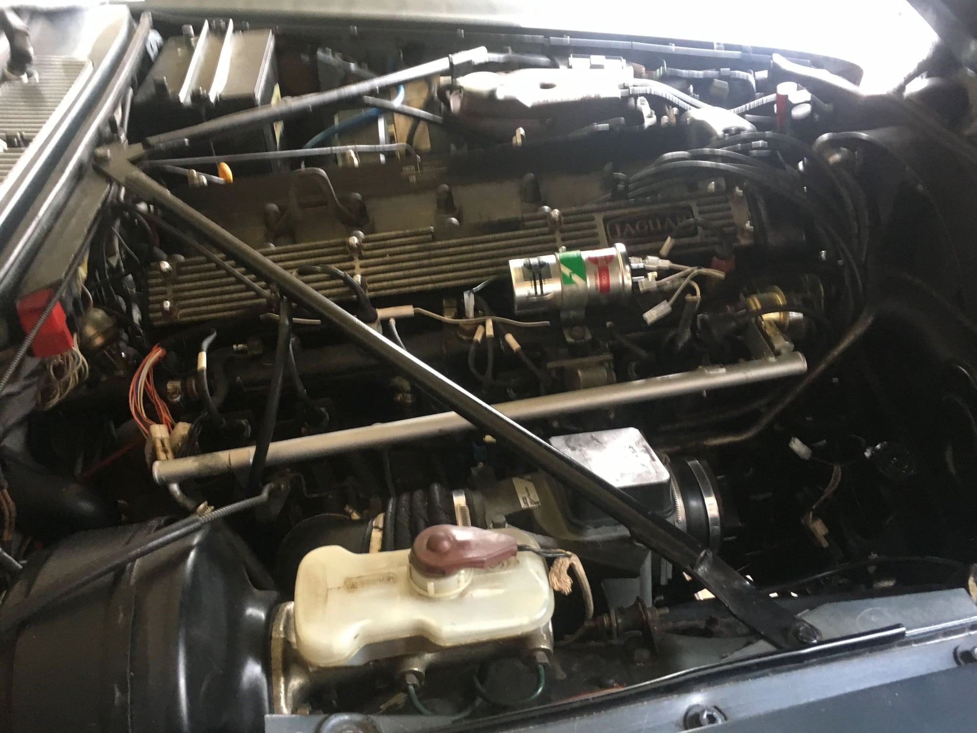
Good evening to all. It has been quite a while since my last thread on this forum. Is there anyone out there who could recommend a good and experienced jaguar mobile auto electrician in the Sydney region? I purchased both the injection and engine ignition harnesses from the UK several months ago and tried to replace them. The injection harness was quite easy to fit as it was a straight swap. But I am experiencing some difficulties with the ignition one. I have reconnected most of the wires but I am not sure which wires are connected to the positive terminals of the coil and which ones to the negative. There is no ballast resistor next to the coil. I have reconnected both wires coming from the amplifier to the coil exactly as they were before removable. Those two wires did not form part of the new harness. At the moment I have 4 loose wires off the new harness. 3 of them are next to the coil. I used a circuit tester and found that, with the ignition key turned on, 2 females connectors has no power but there is power to the third, with a male connector. The fourth female connector, which is part of the new harness, is located under the air filter canister and there is power. I am at a lost here and I would be very grateful for any help. Thank you all. Gerard.
#2
Join Date: Mar 2008
Location: Pacific Northwest USA
Posts: 24,739
Received 10,749 Likes
on
7,100 Posts
The following users liked this post:
Jag7651 (12-14-2018)
#3
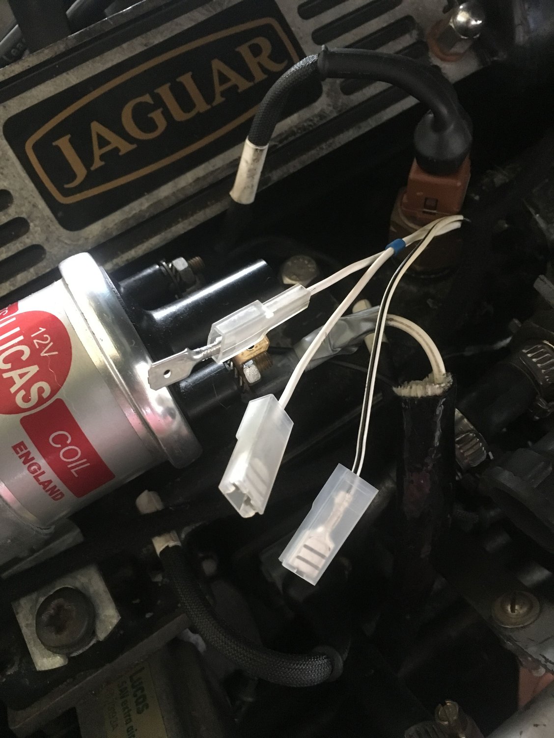
Many thanks for your prompt response Doug. Your great help, as usual, is very much appreciated. The three terminals resting next to the coil:
(1) One fitted with a push in connector but no power is White with a Black stripe.
(2) The other, also fitted with a push in connector and no power, is White with a Blue stripe. There is also a short Blue tape around this wire.
(3) The one fitted with a spade terminal and with power is full white, no other color.
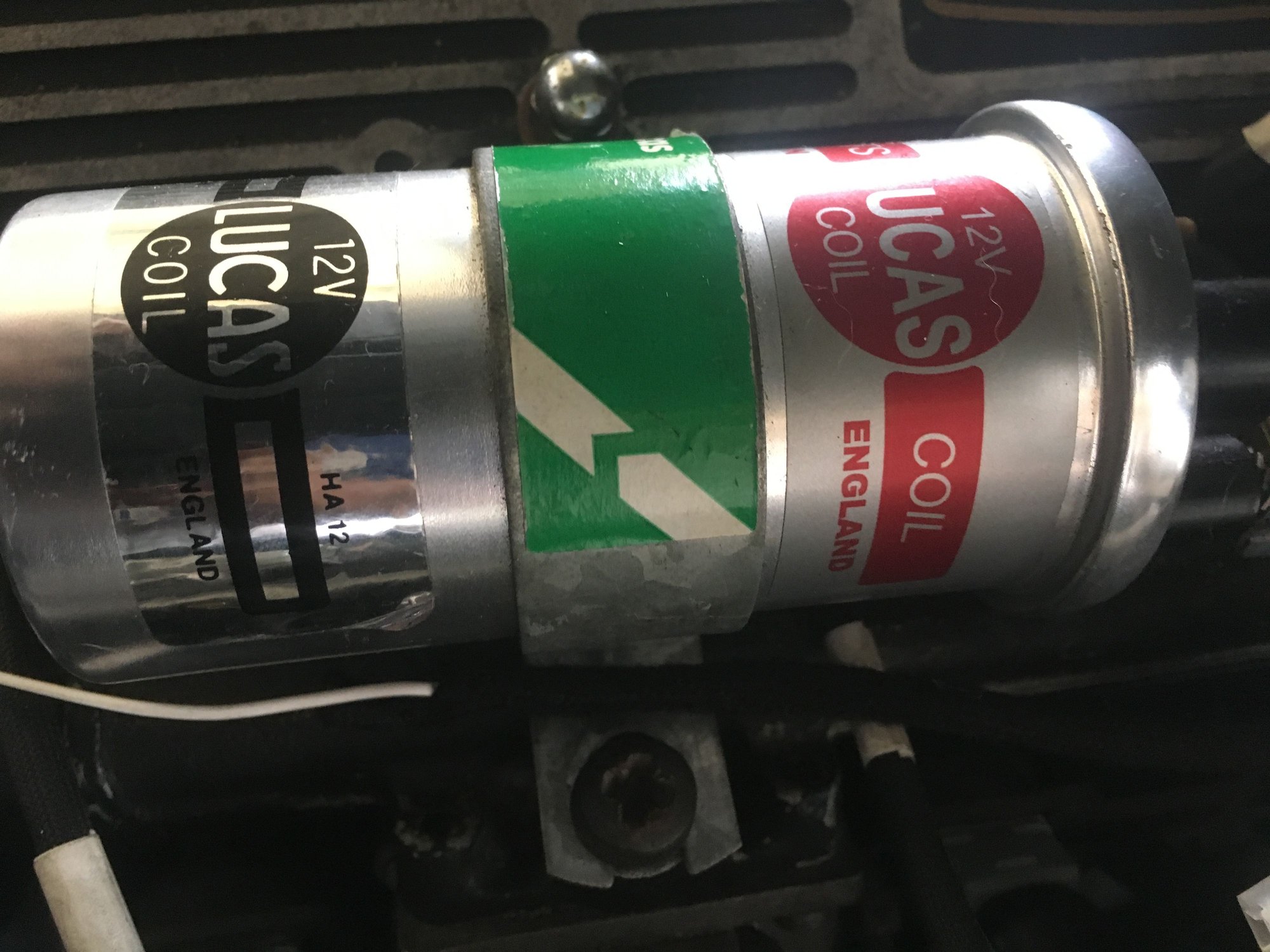
(4) The fourth wire with push in terminal. under the air filter, and with power is White with a Light Brown stripe. This wire is far too short to reach the coil, if it is connected to it that is. But I am not too concerned about the length of any wire or the type of connectors attached to any. I have a good soldering iron and a box full of each type of connectors: quick connect, spade and eyelet. I can lengthen that wire and swap connectors to suit the coil. I purchased the coil new from the UK a couple of years ago and the right one, as per your advice then. I took four pictures of the coil area to include in my message but I do not know how to. My daughter will pop in later to help me with this so, please, expect another message from me in a couple of hours time. Again, thank you for your will to help and to share your knowledge.
Best wishes,
Gerard.
#4
Join Date: Mar 2008
Location: Pacific Northwest USA
Posts: 24,739
Received 10,749 Likes
on
7,100 Posts
Probably goes to the coil negative post but there's also a white/black wire running aft along the water rail. This goes to the ECU and melds in with one branch of the injection harness. This has a bullet connector, typically....which perhaps you call a 'push in' connector
(2) The other, also fitted with a push in connector and no power, is White with a Blue stripe. There is also a short Blue tape around this wire.
Sounds like the tachometer wire going to the coil "-" post....although these are usually white/blue/slate with one of the tracers colors being a spiral
(3) The one fitted with a spade terminal and with power is full white, no other color.
Coil "+" post
(4) The fourth wire with push in terminal. under the air filter, and with power is White with a Light Brown stripe.
Cheers
DD
The following users liked this post:
Jag7651 (12-14-2018)
#5
#6
Join Date: Mar 2015
Location: Dural, Northwest Sydney. Australia.
Posts: 38,884
Received 3,805 Likes
on
2,785 Posts
The following users liked this post:
Jag7651 (12-14-2018)
#7
Join Date: Mar 2008
Location: Pacific Northwest USA
Posts: 24,739
Received 10,749 Likes
on
7,100 Posts
The following users liked this post:
Jag7651 (12-14-2018)
Trending Topics
#8
Hi Doug.Thank you for coming back. I hope you have received the 4 pictures I sent you a few minutes ago.
In your first paragraph: OK this wire with no power goes to the minus side of the coil. Yes, there is a wire with a bullet connector which formed part of the new harness. This is already connected ( picture 4 on the left side of the coil).
The other wire with no power also goes to the minus side of the coil.
The third one with power and spade connector goes to the plus side of the coil. Please have a look at picture 4.
I have reconnected the white wire (with the grey tape) to the plus of the coil. This comes from the positive side of the amplifier.
The other fitted with an eyelet connector to the minus of the coil. This comes from the negative side of the amplifier.
Please confirm the following: After all wires are connected to the coil, I will have 3 connected to the Minus side and two to Plus side.
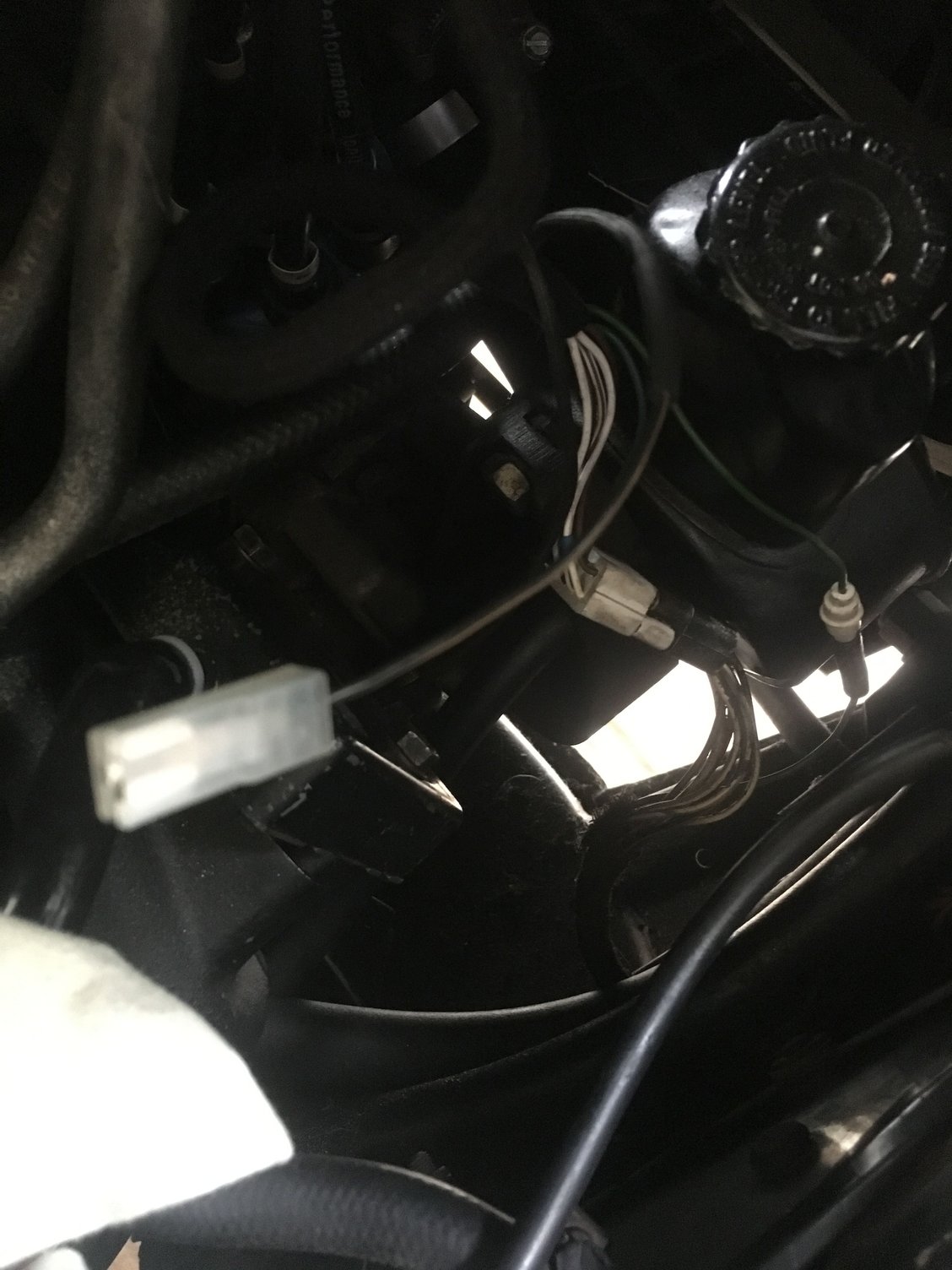
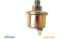
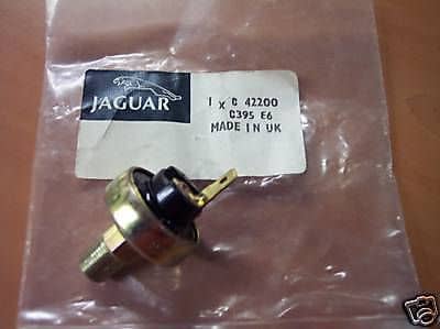
You wrote that the fourth wire with power under the air filter ( picture 4) and which formed part of the new harness goes to the oil pressure gauge. But this wire is too short and will not reach the gauge. There is another longer wire from the new harness ,under the air filter, that fits the oil pressure gauge perfectly. Although I have already connected that wire I did not check for power. Is the oil pressure gauge the small round unit (C46272) and is located close to the starter motor as this is where I connected the longer wire.
#9
Hi Jim. Many thanks for your message, This is great, Dural is only a few kilometres from where I live. You mentioned mechanic. Is he also good in electric wiring? Some mechanics do not want to get involved in any electrical work. Yes please, send me a PM with all his details as I, most probably, will need his services in the future.
Thank you,
Gerard.
Thank you,
Gerard.
#10
Hi Doug. Sorry, I received this message while posting my last message to you. OK, so, I will do exactly what you would do if you were in my shoes. I will go for your instructions in the 4th. paragraph. I will disconnect the existing wire to the gauge sender, ( I will let you know whether there is any power) and extend that short wire under the air filter and reconnect to the gauge. I can also alter the connectors to suit the coil. In the meantime, please confirm that there are 5 wires, in total, connected to the coil. Thank you. Gerard.
#11
Join Date: Mar 2015
Location: Dural, Northwest Sydney. Australia.
Posts: 38,884
Received 3,805 Likes
on
2,785 Posts
The following users liked this post:
Jag7651 (12-14-2018)
#13
Join Date: Mar 2008
Location: Pacific Northwest USA
Posts: 24,739
Received 10,749 Likes
on
7,100 Posts
"+" post should have a solid white wire from the ignition amp and a solid white wire from the main loom.
"-" post should have a a white/black wire from the ignition amp, a white/black wire to the injector loom, and a white/blue/slate wire for the tachometer....although in your case the tach wire appears to be missing one of the colors
Cheers
DD
The following users liked this post:
Jag7651 (12-15-2018)
#14
This is great. I am slowly getting the entire picture of all this! Doug, you are a legend! Thank you so much for your invaluable help and your sound advice. It is now, here, 9.00 am. I am off to shed to reconnect all those wires to the coil, to extend that short wire and connect it to the oil pressure sending unit. I will also check whether there is any power coming from that longer wire which I had previously connected to the sender. Again, thank you very much.
Best wishes,
Gerard.
Best wishes,
Gerard.
#15
Good morning all, This is an update re: 1986 XJ6 series 3.
It has been more than a year that my Jag sat in the shed and not moving. I was unable to start the engine as I did not have the knowledge to locate the faults. After renewing both the injection and the ignition harnesses and, with some invaluable help from this forum, the engine finally came back to life. A very big thank you to Doug as without his advice I would still be battling, The engine, to my relief, is now running smoothly, no rattling, no shaking and no smoking. I did not even have to drain the fuel tanks and replenish with fresh petrol. But I still have a couple of minor problems. The oil pressure gauge on the dash is showing ZERO. I am getting confused with the Oil Pressure Gauge Sender C46272 and the Oil Pressure Light Switch For The Dash C42200. So again, is the shorter wire, in my picture no.1, connected to C46272 OR C42200?. I have extended that short wire but connected it to C42200. Is this a mistake? Any help would be greatly appreciated.
It has been more than a year that my Jag sat in the shed and not moving. I was unable to start the engine as I did not have the knowledge to locate the faults. After renewing both the injection and the ignition harnesses and, with some invaluable help from this forum, the engine finally came back to life. A very big thank you to Doug as without his advice I would still be battling, The engine, to my relief, is now running smoothly, no rattling, no shaking and no smoking. I did not even have to drain the fuel tanks and replenish with fresh petrol. But I still have a couple of minor problems. The oil pressure gauge on the dash is showing ZERO. I am getting confused with the Oil Pressure Gauge Sender C46272 and the Oil Pressure Light Switch For The Dash C42200. So again, is the shorter wire, in my picture no.1, connected to C46272 OR C42200?. I have extended that short wire but connected it to C42200. Is this a mistake? Any help would be greatly appreciated.
#16
Join Date: Mar 2008
Location: Pacific Northwest USA
Posts: 24,739
Received 10,749 Likes
on
7,100 Posts
The following users liked this post:
Jag7651 (01-13-2019)
#17
#18
Join Date: Jul 2012
Location: Walnut Creek, California
Posts: 6,796
Received 2,399 Likes
on
1,880 Posts
!. another great yahoo!!!! Victory is yours!!!
2. Me too. when I installed the "different" engine in my S3, I made the same error as to the oil pressure senders. Figured it out, with help, I am sure.
3. Get the Jaguar Schematic S57 publication. Best I've yet seen. It has helped me a lot. and others as well.
Drive it!!!
Carl
2. Me too. when I installed the "different" engine in my S3, I made the same error as to the oil pressure senders. Figured it out, with help, I am sure.
3. Get the Jaguar Schematic S57 publication. Best I've yet seen. It has helped me a lot. and others as well.
Drive it!!!
Carl
The following users liked this post:
Jag7651 (01-14-2019)
Thread
Thread Starter
Forum
Replies
Last Post
Dalton Spiers
XJ6 & XJ12 Series I, II & III
5
01-14-2014 09:08 PM
Currently Active Users Viewing This Thread: 1 (0 members and 1 guests)

