When you click on links to various merchants on this site and make a purchase, this can result in this site earning a commission. Affiliate programs and affiliations include, but are not limited to, the eBay Partner Network.
Update on my cruise control - its all together now and I have tested as much as i am able.
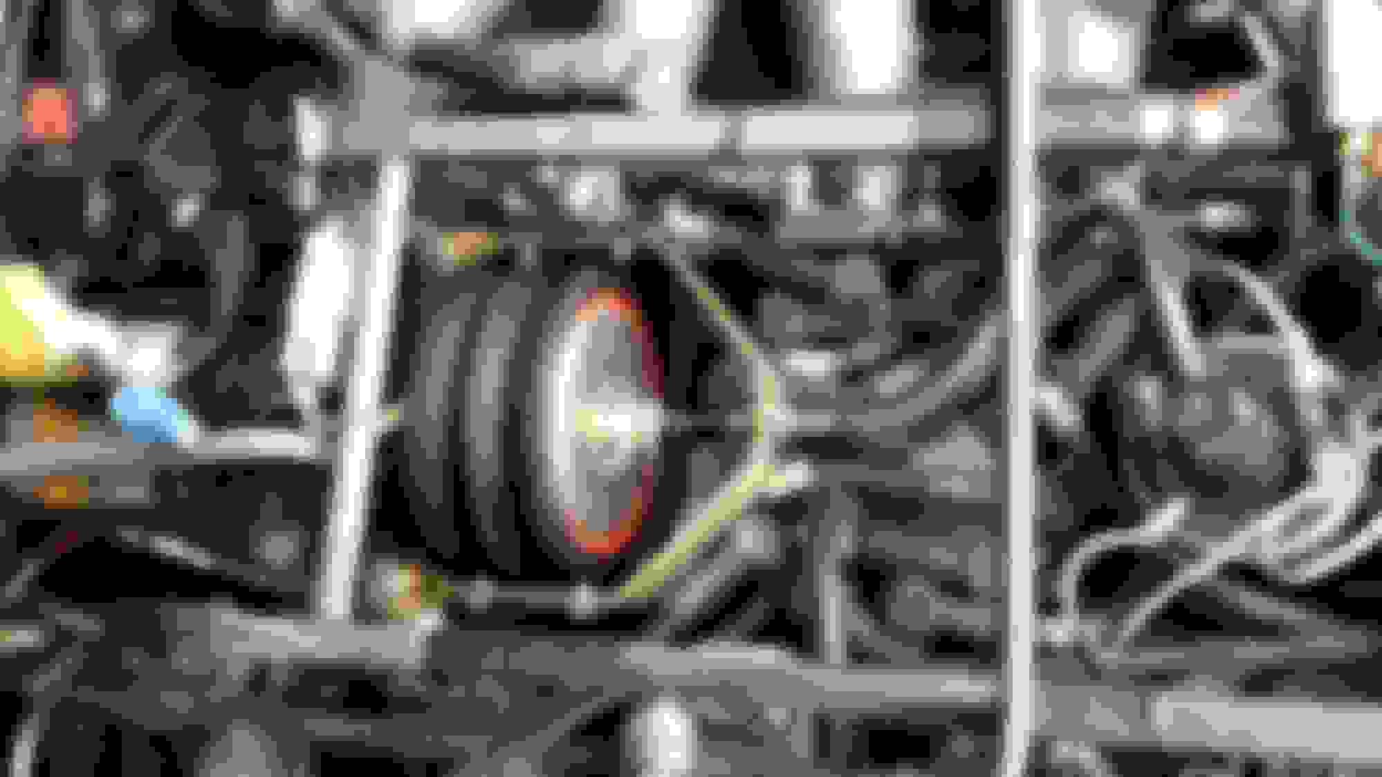
I have manually activated the solenoids and can suck in the bellows from the tube - so all good there.
Went right through all the testing of the wiring and it all checks out except the following....
white / Yellow wire - single signal wire - single connector under dash passengers side (the book says yellow wire) should read 4V AC
I am getting 2.5V AC is that ok?
Cruise control does not work... so the light bulb thingy is next anyone got any ideas?
After the light thing its looking like the ECU is fried.
What fuse is it? I am assuming that the fuse is ok as I get the wiring tests ok.
Things to check
- Is there actually vacuum to the bellows? the hose should be connected to a constant vacuum source.
-On one of my cars the inhibit switch on the brake pedal was shorted internally, so the system was seeing the brakes as always on and thus never let the CC engage. Looks like that is the yellow/white wire, but possible there is a crack in the insulation somewhere and the Y/B is shorting to ground somewhere in the harness?
white / Yellow wire - single signal wire - single connector under dash passengers side (the book says yellow wire) should read 4V AC
I am getting 2.5V AC is that ok?.
W/Y wire is speed interface so voltage here will vary with road speed
Originally Posted by Dukejag
Cruise control does not work... so the light bulb thingy is next anyone got any ideas?
After the light thing its looking like the ECU is fried.
What fuse is it? I am assuming that the fuse is ok as I get the wiring tests ok.
Disconnect the plug at the bellows and measure ohms on the bellows side plug between
Black and Yellow/White - should be 25-30ohms
Yellow/White and Yellow/Black - should be 25-30ohms
Remove the connector from the ECU and at the bellows, then measure ohms on harness side to ground Y/W and Y/B should be open circuit, Black should be less than 1ohm. It is important you disconnect both ends of the harness.
One other thing to check...I went through exactly the process you have only to find that there was a service recall installed for the cruise control which added a vacuum solenoid valve on the supply as an additional safety factor. On my car, this had failed...once replaced, the system worked perfectly. By recollection, the same as the EGR valve. Sits on the RH side of the engine forward of the inlet manifold.
Hi Warrjon - thanks for your input, see results below.
Originally Posted by warrjon
W/Y wire is speed interface so voltage here will vary with road speed
Disconnect the plug at the bellows and measure ohms on the bellows side plug between
Black and Yellow/White - should be 25-30ohms - (27ohms)
Yellow/White and Yellow/Black - should be 25-30ohms - (27 ohms)
Remove the connector from the ECU and at the bellows, then measure ohms on harness side to ground Y/W and Y/B should be open circuit. - (open circuit)
Black should be less than 1ohm. It is important you disconnect both ends of the harness.(3-4 ohms - my guess is bad earth?)
.
Yes 3-4 ohms is very bad and will cause issues, the ground point is G2 which is located on the RH side of the engine bay just in front of the cowl. Try cleaning this up and re-testing the ground.
Warrjon - checked the earths, could not find G2 - downloaded the electrical diagram mentioned by you I believe from another post and it showed where G2 is located.
But it looks like the wiring has been changed and all the earths are together at the front on both sides of the radiator top plate. Checked these and they were loose, now tight and 0.2ohm reading so all good so far.
Raining here now and beer time so not tested yet, but will update when done.
Thanks
I am bored during the week so i am going to make this tester as from the BOOK...
Now i am not the best at electronics and need a drawing of how to wire this up, I did see a picture on line but can not find it.
Could someone kindly draw how to wire this up? Attached is my guess.
Thanks
CRUISE CONTROL TROUBLESHOOTING -- SPEED CONTROL UNIT (IN CAR):If the bellows unit is OK and no problems are found with the cruise control wiring or switches, the only remaining component to check is the speed control unit. The tester shown inFigure 23is simple to make, requiring only two flashlight bulbs, two resistors and some wire. It is also used for the bench test of the speed control unit.
Notes-
a. Length of the three wires is about three feet each.
The two bulbs are 3V flashlight type PR2.
The 33 and 22 ohm resistors are 1/2 watt or larger.
The bulbs and resistors are soldered as shown.
Small alligator clips will help in connecting.
All components can be purchased from Radio Shack, about $6.
Mount this assembly on a piece of cardboard about 4 by 6 inches.
Disconnect the connector from the bellows unit and connect the three wires from this tester to their respective colors on the wiring harness (not to the bellows unit). The bulbs and resistors take the place of the two bellows solenoids so that we can observe the operation of the speed control unit. Route this assembly out from under the hood and use a windshield wiper to hold it against the windshield so you can observe the bulbs while driving.
Next go for a drive. At about 30-40 mph push the "set" cruise button. The bulb on the left (33 ohm) should light but rather dimly and stay lit. This bulb is taking the place of the yellow-white solenoid that closes the bellows to the atmosphere.
The right bulb should light but flicker, and, as you slow down the bulb will light brighter, and as you speed up it will grow dimmer. This bulb is taking the place of the yellow-black solenoid that controls the vacuum from the engine.
If this bulb test circuit works, then the speed control unit and associated wiring/switches are good. If this test fails then the speed control unit is possibly at fault.
Ok - I built my little test thing and went for a drive... nothing, not even a little light from the bulbs.
Not the best soldering but ...... it does the job.
I was dark so easy to see if there was a light.
Came home and tested the lights with 12v
earth on BLK -
12V on the Y/W wire and one bright light
12V on the Y/BLK wire and two dull lights as they are in series.
Sounds like the ECU is dead. I have mine here somewhere, I'll test it and see if it's working and repair if dead. My car has VR Commodore cruise control so my ECU is not needed.
Sounds like the ECU is dead. I have mine here somewhere, I'll test it and see if it's working and repair if dead. My car has VR Commodore cruise control so my ECU is not needed.
Warrjon, are you offering to sell yours if you can fix it?
That would be great.
Quick question - i have not checked the fuse but if it was blown common sense tells me there would be no power at all?
Where as I have power were needed.
There are 2 fuses #5 in the main fuse panel and #3 in auxiliary, sorry I made an assumption these were already checked. If you have 12V at the YW & YB wires the fuses are probably good.
I put my ECU on the bench today and from my testing it looks like the IC is bad. The IC looks like a proprietary chip, I have VSS input and the set/res inputs go directly to the chip through resistors and I have no output from the chip driving the output transistors, so my ECU is a bin job.
Having mine apart there are 2 transistors in the corner of the PCB, ZTX750 and ZTX650 these are the output transistors that drive the vacuum solenoids, (mine are good) but if there has been a short at some time one or both of these could be faulty.
If your DVM had Diode function then you can test them. If it does not have diode function let me know and I'll give you the procedure to test with Ohm meter.
Both Transistor legs are as follows
Centre pin B
Outside pin C
Other outside pin E
ZTX650
Red Probe to B and Black Probe to E about 0.6V
Red Probe to B and Black Probe to C about 0.6V
Swapping Probes so Black to B should give no reading or open circuit
C to E one way will read 0.6V and open circuit the other way
ZTX750
Exactly the same but the probes are swapped, so Black Probe to B and Red Probe to E will give 0.6V etc.
I looked it up quickly and it does have diode test function. It's with the Ohms range and you push the blue button to get to diode function. I am more than happy to Skype if you want help.

 04-24-2019, 09:55 PM