When you click on links to various merchants on this site and make a purchase, this can result in this site earning a commission. Affiliate programs and affiliations include, but are not limited to, the eBay Partner Network.
I have a question- how smooth is the idle of your set up with bigger throttle body COMPARED to stock?
A good way to assess this is to put your hand on the steering wheel and shifter knob during idle and you shouldn't be able to feel vibrations through them.
The reason I ask is that the throttle body size effects this as our cars use the electronic throttle to control idle and during development there was always this compromise of WOT outright flow vs idle speed control.
For most it doesn't matter, for me however, I want my car to be as smooth as possible (already I dislike the mina gallery intake tube and XKR 4.2 power flap due to the noise- so I'm looking at recalculating the Helmholtz frequencies/quarter wave of the bigger zip tubes). When I go for more aggressive cams with more overlap, this could exascerbate the situation. Therefore I may settle for less than 90mm, may be 82-85mm, although I haven't decided yet.
Are there bosch throttle bodies that are in that size range that have the same bolt pattern?
Thanks
Noise from the intake is different for me, as I use a thick silicone covered pipe to a large filter in front area of the bumper.
The idle question is maybe more for other TS owners, as I am already running aggressive cams for a long time, so am not able to tell what the difference was anymore.I would say the idle was very smooth, i.e. no difference than before the bigger TB.
I have had the box designed with a 2 slope approach that may have contributed to that (which can be manually adjusted if required). So for example the 1st 10% of pedal move would only account for actual 7.5% of throttle move, and that provides a more comparative butterfly movement closer to the smaller stock one in airflow (amongst others). I don't have the bolt pattern on the Bosch TB, it�s for pinkbatmotorspsorts or deuce2000 to confirm, though it definitely is closer to Jaguar then to the Hemi ones I used.
There will be additional research to perform trying to use Deuce2000's TB on different model year Supercharged engines. For the earlier 4.2 engines the throttle body used a separate TPS and actuator. On 2006 and newer, Jaguar used Throttle bodies with the TPS integrated into the actuator. (See picture.) The proposed TB that Deuce2000 will be using on his engine does non have coolant flow through the side of the TB. This is ok for a performance engine where the owner is doing regular service and inspections, but on daily drivers, you will get more carbon/oil deposits around the butterfly because the throttle body isn't heated up by the engine coolant.
- Deuce 2000. Where is the TPS on the throttle body you are using? Is it integrated into the actuator?
-[[i]I wonder if the 2006 TB change runs the same electrical for the TB actuator motor, and if the TPS voltage curve is the same. - Anyone compare the 2 by chance?]
-{I am personally curious because I recently purchased a low mileage 2006 Supercharged 4.2 I plan to put in one of my 2003 STRs with bad engines. I am presently comparing the differences between 03 and 06 electrical. The TB is one of the differences.}
I added images of a 4.2 NA TB and a late model XKR TB. Note that the XKR TB used the same TPS/Actuator, but the bolt pattern on the 5.0 engine's TB is different
Last edited by Tijoe; 10-16-2018 at 10:31 AM.
Reason: added wrong image
you must increasing the diameter of your intake duct like my. 83mm
I am curious as to what you have done to overcome the limitation of the actual intake into the supercharger?
Weakest link and all that.
I liken it to a 3 lane highway funneling into a 2 lane highway. You can lengthen the 3 lane highway and reduce the length of the 2 lane and you still have the same congestion.
Reason I ask is that I considered an enlarged TB but discounted it because of the limitation I referenced above.
Ok I take back what I said.
I just measured the perimeter of the inlet to my original M112 Gen V SC and it measured about 336 mm + or -..
The 83mm diameter TB gives a circumference of 261 mm rounded up.
A stock inlet for a 4.0/4.2 would be close to 2 PSI vacuum, which can be worse pending the filter status.
Next, by increasing airflow into the engine (lets take pulleys) you only increase the vacuum in the intake.
Several restrictions in the inlet will cause this vacuum before the supercharger, and that all the robs precious power, here is a good overview from KenneBell showing the effects on twin-screws:: Supercharger Boost vs. Inlet Loss | Kenne Bell
The TB is just one of course, its the piping (diameter and bends!), MAF Filter, Stock airbox and intake elbow, so the full intake need to be taken into consideration.
Here a (rough) overview of the surface areas:
As the TB sits close to 2 sharp 90 degree bends, it may be better to go for a bigger one for a better flow (with matched piping/inlet of course)
90mm would be overkill for the Eaton setups but 83 or 85 ones are possibly the best bet to achieve the lowest vacuum.
sometimes for me it is really a titanic undertaking to fully understand all the concepts you express here ... but I try to answer:
I have enlarged the manifold but also the mouth of the compressor. Thinking about how the rotors rotate, I channeled the air to the outside of the casing making slides. taking a cue from the work done at the Jokerz performance (of which I enclose a photo even if it is not my compressor).
once the air inlet of the compressor has been worked (also in the upper part between the 2 bearings where there is an unexplained wall that goes downwards, now flattened by me) I have measured the areas and the 83 mm TB will be perfect since the manifold areas are larger and the compressor inlet is larger. And finally I welded the side cuts to the air outlet of the compressor.
the most difficult part to work with the collector is the central part, where from round it becomes oval. I did hours of work in my garage with various hoses (mini dremel, cutters with elongated stem, flexible connected to the drill etc.) and in the end I managed to enlarge it but it was really difficult.
My XKR is from 2005 (like all in this x100 section of the forum) and therefore it is not the version from 2006 onwards (x150) that has another section of the forum.
therefore my TB is the one you showed 2002/2005 with 2 electrical connections.
I do not understand why there should be coal deposits in the TB without cooling. we consider that I will install this TB with probably a motor vapor decanter and without EGR (I will install a programmable motorport control unit instead of its original dense one).
all this then, in my case, will be installed in my new 4.8L engine so my tests and my subsequent tests will not be comparable with the traditional 4.2L engines.
remember also that all the intake duct I will install is 90mm with dynamic air intake in the bonnet and therefore also quite short in length. There will be no problems for the MAF as the motorsport control unit (MOTEC) will be able to cope with all the problems and solve them.
Obviously, if there are more technical and specific questions about the new TB they are doing, you should contact PinkBatMotorsport and Nigel will give you all the possible info and will tell you at what point is his design for us.
Last edited by User 070620; 10-17-2018 at 01:39 AM.
I wanted to show just how bad the soft carbon deposits in a SC car can be. after maybe just 50k miles.
They are mainly due to the high load breather funneling bypass gases back thru the inlet below the TB. Those deposits are present throughout the cooling matrix inside the charge coolers effectively cutting back on the cooling effect they have on the inlet charge.
That is why I have fitted an oilcatch can on the high load breather. The EGR has much less effect on the carbon deposits.
When I did all my work on the supercharger I had it polished and ported as well as a smaller pulley installed. I polished and "ported" all other components so there were no "lips" in the way of airflow.
Many arguments in this forum stating that porting and polishing an Eaton M112 Gen V is a waste of time. I had it done anyway.Also had later model rotors and gears installed which were supposed to be a little better than MY 2005 rotors.
I also installed a stage I inlet pipe as well as other mods including meth/water injection which also helps keep the inlet track clean.I do not have an ECU tune to take advantage of the Meth/water injection but at least it will help stop any knock induced timing retardation on heavy acceleration. I can even run just fine on 87 Octane fuel.
I now have a car that will easily spin excellent tires even when the car is moving at low speed. IF the tires grip on a good surface I feel a bit of whiplash.
Lots of details in the post "quest for 450 hp".
I should add that in retrospect I have often thought that I should have gone with Avos's twin screw set up when it was available!!!!!
>I do not understand why there should be coal deposits in the TB without cooling. we consider that I will install this TB with probably a motor vapor decanter and without EGR (I will install a programmable motorport control unit instead of its original dense one)>
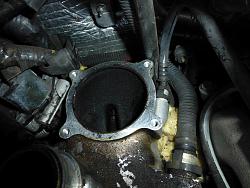
Another way to state what John wrote is that hot oil vapors that are high in carbon are drawn out of the engine are sucked into the elbow below the throttle body. The butterfly in the throttle body is a restriction at other than WOT. This creates a pressure drop and air velocity increase that creates a cooling effect on the air. Carbon and some of the oil vapors condenses in the elbow and flows up onto the butterfly valve. When the throttle body is heated using the coolant, the higher temperature minimizes the deposition rate.
Those oil vapors also clog up the charge coolers to quite a degree. It is soft and can be dissolved by soaking in a good solvent when they are removed.
Many people make all sorts of mods on SC cars and pay no attention to a significant power robbing situation which probably exists on many 4.0 and 4.2 SC cars starting,I am guessing, around 50k miles.
Here is a pic of the elbow below my TB when I was taking everything apart at about 100k miles. That same type of deposit is in the SC cooling matrixes. and they have narrow passages .
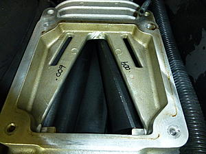
For what it is worth in the pic I am showing here you can see the "porting" that was done "professionally" on my M112 Gen 5.
If you look carefully you can see it is not evenly done. I could do a better job myself.
Supposedly it is for a gain of 10-15hp. I personally do not believe that it is anywhere close.
I was told that this porting is all that is "worth" doing by an expert. I believe him but his tech did not exactly do a great job. I am not naming names
however this expert is very well known in the racing world.
That company sold all assets to another company a year or so ago. and the engineering expert went along as well.
I took apart the throttle actuator on a Jaguar 5.0L Throttle body, to see if the actuator and TPS were the same as the older throttle bodies on our 4.2 engines.
This generation throttle body is completely fabricated in China and has no similarity to the 2 Denso based throttle bodies used on the 4.2 motor. Besides the different bolt pattern, the throttle actuator's TPS is completely different. The motors all have a 12 tooth gear on them but the middle gear and butterfly gears are different on the 5.0 TB.
This one was a pain to get apart due to the spot welded motor leads. This TB is obviously intended not to be serviced. (Another disposable part.)
My Pentatorx Security bit set arrived today. I was able to remove the cover (Size TS20) to the 2002-2004/5 throttle body and have a look inside. I like the quality of this generation better than the 2006 on version. (All metal gears, just looks better.)
I don't want to hijack this thread regarding questions on the next gen. 4.2 TB, but I have questions pertaining to the hall effect sensor style use in the later ones.
Should I bring this thread back to life, or seek answers in this thread? https://www.jaguarforums.com/forum/x...acement-77560/
I was not able to measure a voltage change for the hall effect sensor TPS that is built into the later Throttle bodies.
Has anyone dealt with these sensors?
It is looking like I have to use the earlier 2002-2005 TB on my newer engine to make it compatible with my 2003 STR.
Deuce, Is the 83mm TB you are using have a built in TPS? Is it a hall effect type? This may be a problem for you to use in your engine build. (Perhaps you are adding the Denso TPS to the other side of your TB.)
You can usually find the min/max voltage values in the electrical guides, you can find these on Gus his site.
As deuce2000 mentioned he would go for a Motec ECU instead of the Denso, it basically doesn't matter anymore what TB he is going to use as the Motec ECU an handle different types.
You can usually find the min/max voltage values in the electrical guides, you can find these on Gus his site.
I am able to measure the ohms and voltage drop across the separate Denso 198500/3300 TPS, but in the next generation integrated Hall Effect sensor, I am unable to measure/read a voltage change and the Ohm readings stay the same as I open to WOT and close the throttle body butterfly.
I have the electrical schematics for both types of throttle bodies.
Who is "Gus" and where is his site? Thanks for clarifying that Deuce is using a different ECM..
Last edited by Tijoe; 10-24-2018 at 09:25 AM.
Reason: spelling
I spent a couple of hours looking through the "JagRepair" web site looking for the differences between the 2002-2005 TBs and the 2006 to 2011 Throttle bodies. There was a Denso ECM change at the same time Jaguar went to the 2006 onward TBs.
One of my answers I was looking for is that one can't measure Ohm resistance through a "Hall effect" style TPS. From a 2006 Jaguar electrical guide: "A Non-Contact position sensor requires a forward bias voltage to operate, so it cannot be Ohm-tested."
Something I researched is that Jaguar/Ford was behind the technology curve in implementing the "Hall Effect style" TPS in the 2002 time frame. The rest of the auto industry started moving towards integrated hall effect sensors starting around 2000. ROW V8 engines 4.6L and larger were already using the Hall effect style sensors.
1. I haven't been able to find a throttle body larger than 75mm that have a separate TPS and throttle actuator.
It appears that in the 2002-2005 time frame, separate Denso TPSs were use Primarily on Jaguars, Toyota and Lexus. The Majority of these cars have smaller engines that used smaller throttle bodies. Therefore it would be a lot of work to put a 83mm TB using a Stock ECM on a X100.
2. Regarding the Throttle actuator, 12V motors are PWM controlled and I am not sure if they are Voltage or Current mode controlled. (Another topic to research.) Therefore I am not sure how compatible different throttle actuators would be with our generation ECM. - I give more credit to Avos, because I am sure he is several years ahead of the rest of us regarding what throttle bodies could or would work on our cars.
Adding more information to this thread: If we could use the X150 TBs on our X100s and STRs we would have another spare option. I picked up a Toyota TB and it is almost the same as the 2006+ Jaguar TB.
As far as I can tell, only the water coolant lines are different. These Toyota TBs can be purchased new for 1/2 the price of our Jag TBs.
I have a question to the Count. Deuce has modified his generation intake manifold to accommodate a 82/83mm throttle body. In next generation Jaguar 4.2 SC engines Jaguar and Rovers went with the design where the intake air runs down the center top of the engine. Do you know which design has better inlet air flow? Perhaps the X100 hood is too low to convert to the later SC intake. Just thinking....
I have a question to the Count. Deuce has modified his generation intake manifold to accommodate a 82/83mm throttle body. In next generation Jaguar 4.2 SC engines Jaguar and Rovers went with the design where the intake air runs down the center top of the engine. Do you know which design has better inlet air flow? Perhaps the X100 hood is too low to convert to the later SC intake. Just thinking....
I do not think there are many differences. The flat manifold of the later versions in my opinion is very narrow but allows more easily to create a "dynamic" air inlet towards the front.
I managed to do a dynamic air intake in our narrow engine compartment, modifying the bonnet.
the main thing, however (as the Ferlito team confirmed to me) is how the inlets and outlets of the cooling water of the intercoolers are placed.
this is my modification. Front inputs, rear outputs.
The middel intake setup from the str isn't that optimal from what I have found, and for the x100 thanks to enough room at the back of the engine you can eliminate one 90 degree turn (so from the pipe to the TB if you turn the TB as well)
With regards to the TBs, it is to long ago that I checked the TPS output of the 2006, but am I remember seeing very different TPS voltages compared to the older cars, so not usable.
I only know that the current is measured to check over an current, I don't think the ECU would use current to control the motor.
The X100 and earlier STRs had 390HP ratings, and they had different intake set ups. When VVT was added, to the supercharged versions the ratings went up to 400HP. The X150 supercharged 4.2 was rated at 420HP. Where did this additional 20HP come from? The split rear intakes? The same year XJRs were rated at 420 HP and they have the inlet over the top of the engine then split dual inlets in front of the inlet duct. I believe that the Range Rovers stayed at 400HP until the put in the 5.0L engines.
Last edited by Tijoe; 10-29-2018 at 08:30 PM.
Reason: Spelling

 10-11-2018, 12:05 AM