When you click on links to various merchants on this site and make a purchase, this can result in this site earning a commission. Affiliate programs and affiliations include, but are not limited to, the eBay Partner Network.
Facelift tail lights on Pre-Facelift. (Worked, but??)
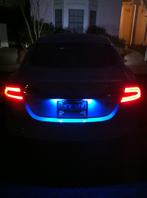
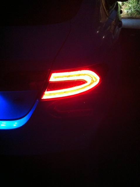
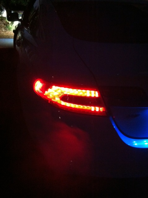
Ok, so I'm kinda in the process of building my own hybrid XF. I'm blending facelift parts and also aftermarket parts to create my own perfect machine. So I purchased some 2012 tail lights, also the lights that are attached to the chrome plinth. So I started with just the tail lights and all went well, looked amazing, same connector, plugged right in. My problem is the lights worked, but when I apply the brake, it doesn't get any brighter. Also, the turn signal does not want to work. Any thoughts???? I have pics below.
I am sure the LEDs have a different voltage draw and somebody smarter will be able to explain that better. But I do not think that the electronics of the 2011 and older can handle that.
I believe Schwabe is correct. What was half power (running light mode) for the old taillights is full power for the LEDs. Thus, when you hit the brakes, there is no brighter to go. There is no simple solution for this. As a start, check out these links:
It's telling me I can't view cause I'm not a member. I can however look at that forum, just not from your link. So if you could tell me what page it is on and the name of the thread, I can look for it. Thanks!!
It's telling me I can't view cause I'm not a member. I can however look at that forum, just not from your link. So if you could tell me what page it is on and the name of the thread, I can look for it. Thanks!!
register....its a good forum and all the info on pin locations for wires in the sockets and info on a resistor to make them flash at the dash at the right rate. Net of it is that it all works just more work.
Sample:
TA DA.... Fitted lights using all OEM fixings. Bolts are all identical between 2010 and 2012 models.
As mentioned previously, plug and socket arrangements are identical between both sets of lights however the pin configurations are different.
Needed to get wiring diagram form TOPIx and then change the pins around in the new light (this will ensure a swift exchange back to the old light unit if necessary). The pins can be removed from the socket, on the light, with the use of a strong needle poked down beside the pin.
Once the pins are removed they need to be re-configured to match the old light. Pins moved to suit, looking at socket, top left to right:
1 = Tail
2 = Stop
3 = Negative
4 = Reverse
5 = Turn
A couple of items to mention:
I didn't bother with the boot part of the tail lamp as this would entail additional cable to the looms. This means that a small piece of black plastic is visible on the side of the light which would normally have been covered by the lower boot lamp.
All lamps worked great, nice and bright, indicators flash at normal rate but, as suspected, being LED's, the indicators require a 50 ohm resistor across each lamp to stop the dash repeater flashing irregularly.
It's telling me I can't view cause I'm not a member. I can however look at that forum, just not from your link. So if you could tell me what page it is on and the name of the thread, I can look for it. Thanks!!
It sounds like the lights will bolt/plug in but the wires need to be swapped around. The blinker indicator on the dash flashes erratically if you don't put a 50 ohm resistor between the plug and ground on the tail light.
If you didn't move your wires around I'm surprised they work at all... Maybe the ground is the same but the others are swapped around so they happen to light up.
Regarding the 50 ohm resistor. I searched ebay and noticed they say watts and ohms. What should the watt be?
The wattage is the amount of energy the resistor can dissipate without failing. When in doubt get the larger wattage. If the wattage is too low the resistor can heat up and burn anything it is touching. Generally, the higher the wattage the larger the resistor. Usually there is more surface area to dissipate the heat.
Depending on the voltage running through that line (5V or 12V) you can calculate what you need. If it's 5V then you'd need at least a 1/2 Watt resistor. If it's 12V you'd need ~3 Watt resistor. You could test it with a multimeter to verify the voltage.
Formula to calculate wattage = V^2/R; (5V case) 5*5/50 = 1/2 Watt
I've successfully done it. You need to swap a couple of wires around for the brake lights, and add resistors for the indicators. Didn't take much work to be honest.
i did facelift tail lamps, mine plugs was completely diferent placements(even GND was diferent) that was easy parts actualy, i have sucesfuly aded gearshift console, dashoard buttons , and now working on climate control(this is absolutely diferent units, need to use facelift pcb to exterior+ buttons +leds,and the main board do all job.
so far i have a bug of climate control- too sensitive comparing to original -one turn means one up or low fan level(diferent digital encoders)
there is no schematic on boths manuals of those units so its real pain in the..
Any tips on doing this ??
Maybe some pictures of the rewired plug?
What resistors to use !! I would do a diy with clear pictures and post it back here...
For anybody wanting to do the 2012-2015 rear light retrofit to a pre-facelift !!! I've just done it.
It's pretty simple once you get the feeling for it.
Just remove the old rear lights and put he new ones in..
Right ?? Almost right...
The connectors are the same but the pin layouts are different !
I choose to do this on the connector on the light itself, as this makes changing to the older lights easy should you want to sell the car... or something !!!
Also easy access to light unit, makes it easier to work on !!
I spent a lot of time figuring out how to get the bloody pins out of the connector (few hours).
Keep in mind that I didn't add the resistors yet... so you'll get the hyper-flashing inside the car, but they'll flash at normal rate on the outside.
Both light units have different wire colors.
So I took a picture of the connector from the backside !!
Also missing from many topics on this mod is de wire colors and their respective function.
On the photos I made you'll see the pin layout, wire colors and wich nr they represent and their function..
Excuse the dirty fingers, but I was using everything I could find to get those bloody pins out !!
Should be the same for you, but always check !!
This worked for ME..
If somehow you have different wire colors you can do the test yourself.
Just add 12V negative (black) to the black wire and the positive (red) to the other pins and see what lights up !!
Rear left and Rear right as seen from the back of the car !!
To be clear :
Left------ bootlid------ Right 😂😂😂😂
Hope this helps you guys looking to do this mod !!!
I'll take pictures in the daylight and post them here.
PS: I haven't done the lights on the bootlid.
I like it better this way !!!
Looking at this now I wish I hadn’t replaced my broken tail light with the original one. Looks very good and modern. The older lights aren’t bad either but this looks like it just rolled out from the production line. Good job to everyone who did this!
register....its a good forum and all the info on pin locations for wires in the sockets and info on a resistor to make them flash at the dash at the right rate. Net of it is that it all works just more work.
Sample:
TA DA.... Fitted lights using all OEM fixings. Bolts are all identical between 2010 and 2012 models.
As mentioned previously, plug and socket arrangements are identical between both sets of lights however the pin configurations are different.
Needed to get wiring diagram form TOPIx and then change the pins around in the new light (this will ensure a swift exchange back to the old light unit if necessary). The pins can be removed from the socket, on the light, with the use of a strong needle poked down beside the pin.
Once the pins are removed they need to be re-configured to match the old light. Pins moved to suit, looking at socket, top left to right:
1 = Tail
2 = Stop
3 = Negative
4 = Reverse
5 = Turn
A couple of items to mention:
I didn't bother with the boot part of the tail lamp as this would entail additional cable to the looms. This means that a small piece of black plastic is visible on the side of the light which would normally have been covered by the lower boot lamp.
All lamps worked great, nice and bright, indicators flash at normal rate but, as suspected, being LED's, the indicators require a 50 ohm resistor across each lamp to stop the dash repeater flashing irregularly.
Do i need resistors only on the indicators? 2011 to 2015
 02-08-2014, 07:01 PM