
Nav Upgrade 04 XJR x350, OEM Touchscreen


Thread Starter
|
Veteran Member
Joined: Jan 2012
Posts: 1,174
Likes: 743
From: Sunshine Coast QLD
I'm about to order a new Touch Screen controller to replace the one I'm currently using
So I get the order correct I need to know the pitch of the ribbon cable that connects the touch panel to the head unit PCB.
Does anyone have the specs or a pic of the cable.
The original module I have installed was fitted by an installer so I don�t have the info without pulling apart the unit to find out. The installer ordered more than one module with different cables so he does not know which one either without doing the same thing.
I'm trying to avoid pulling apart the head unit an extra time to find out
Here is link to what the cables look like that I�m after
http://www.customgadz.com/store/img/...4-thickbox.jpg
http://www.customgadz.com/store/img/...3-thickbox.jpg
For those interested this is the unit I have installed
Remote touch for Android - customGadz
OEM Touchscreen Switcher Add-On - customGadz
What its does is allow an Android or Iphone to be controlled via the touch screen
This has 2 Modules the controller and the switcher. There is a video of the system in action on the product page above.
The Switcher redirects the touch screen to the controller
The Phone Video out is connected to the RGB interface
The Phone Audio out is connected to the ACM interface
The Touch control is connected to the Phone Via bluetooth
When the Phone is active the whole screen is active on the OEM screen including the touch control
I'm running Music and Nav (igo Primo) via the Android.
My next step is to Add a a new nav setup that uses WinMobile 6, again with Igo Primo
As a result I need to re-interface the touch screen, not sure if im keeping the android or replacing altogether yet
PS this is the nav computer I�m fitting next
CS9200RV Navigation Box (for OEM Monitors) - Navigation Systems and Boxes - GPS Navigation - Car Solutions Online Store
Cheers
34by151


Veteran Member


Joined: Apr 2008
Posts: 3,713
Likes: 1,698
From: Ottawa, Ontario, Canada
This is fantastic! Thank you.
I look forward to the end result.
I look forward to the end result.
Thread Starter
|
Veteran Member
Joined: Jan 2012
Posts: 1,174
Likes: 743
From: Sunshine Coast QLD
With a bit of luck the lat part I�m waiting on Ships on Monday. So guessing around 2 weeks for it to get from Russia to OZ
Still deciding on the ideal location for the turn/blind spot cameras.
Possible locations
1. Under the Mirrors, next to puddle lamp
2. Rear shelf, in either corner
3. Rear shelf, in the middle
4. Under the High Mount stop lamp
5. Rear Bumper, on the side behind wheel, above reflector
All have there pro's and cons
What I have decided to do is to tape them on in each location and go for a drive. Ill decide from there
Ive attached the circuit diagram and parts for the camera setup (with parking guide lines)
Also a Pic of the side cameras
Cheers
34by151
Thread Starter
|
Veteran Member
Joined: Jan 2012
Posts: 1,174
Likes: 743
From: Sunshine Coast QLD
Just got word that the items I have waiting on have been shipped
Not sure how long it will take to get from the Ukraine to OZ, hoping its not long
So the new
screen interface + usb programming module and IR receiver
Bluetooth module
Are all on the way. I'll be installing as soon as its here, shame It missed the long weekend here in OZ though
Cheers
34by151
Not sure how long it will take to get from the Ukraine to OZ, hoping its not long
So the new
screen interface + usb programming module and IR receiver
Bluetooth module
Are all on the way. I'll be installing as soon as its here, shame It missed the long weekend here in OZ though
Cheers
34by151
Thread Starter
|
Veteran Member
Joined: Jan 2012
Posts: 1,174
Likes: 743
From: Sunshine Coast QLD
Just got word the last parts have arrived. Sadly they came too late to install this weekend and I'm going away next weekend. Expect to have it all done in 2weeks time
I have managed to finish the diagrams. Haven�t checked them yet so there may be errors. so I wont post them till I do the install but if anyone wants them PM me
Cheers
34by151
I have managed to finish the diagrams. Haven�t checked them yet so there may be errors. so I wont post them till I do the install but if anyone wants them PM me
Cheers
34by151
Trending Topics
Thread Starter
|
Veteran Member
Joined: Jan 2012
Posts: 1,174
Likes: 743
From: Sunshine Coast QLD
Finished bench tests which have caused a few changes in plans mainly the location of some of he parts to make the cable runs easier and for the bluetooth signal strength
Boot gets the new video interface and camera switch
Side cameras on rear shelf
Rear camera in Lic plate frame
Behind glove box, nav unit, audio mixer
Glove box shelf, WDtv, 2tb usb hdd, SD card extender
Cable runs are now
2 * RGB shielded cables to the rear for RSGS + 2 Composite video signals
9 core data for control signals
Antenna for GPS, WiFi and 4G internet move from the rear parcel shelf to under the dashboard
Have a 3 day weekend next week so fingers crossed the whole install will go as planned then. Install pics and how to guide to follow
Cheers
34by151
Thread Starter
|
Veteran Member
Joined: Jan 2012
Posts: 1,174
Likes: 743
From: Sunshine Coast QLD
Good Plans laid to waste.
Got the rear camera in and replaced the video interface when I got a call that my uncle was in intensive care.
Fired up the plane and flew from Sydney down to Adelaide to pickup some relatives and on to Bathurst (3000km)
So the XJR is pulled apart in the hangar in Sydney half done, not that I care too much at the moment
34by151
Thread Starter
|
Veteran Member
Joined: Jan 2012
Posts: 1,174
Likes: 743
From: Sunshine Coast QLD
Some Pics of the work so far
Picture links are here
http://s1305.beta.photobucket.com/user/34by151/library/
Rear Camera
You will notice only one cable. I used a cable that has a combined RG59 and power.
RG59 / Power Cable - Jaycar Electronics
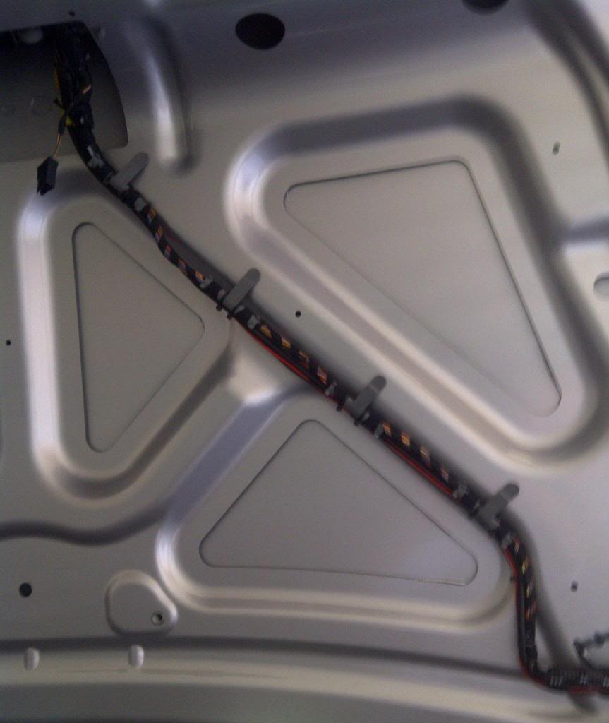
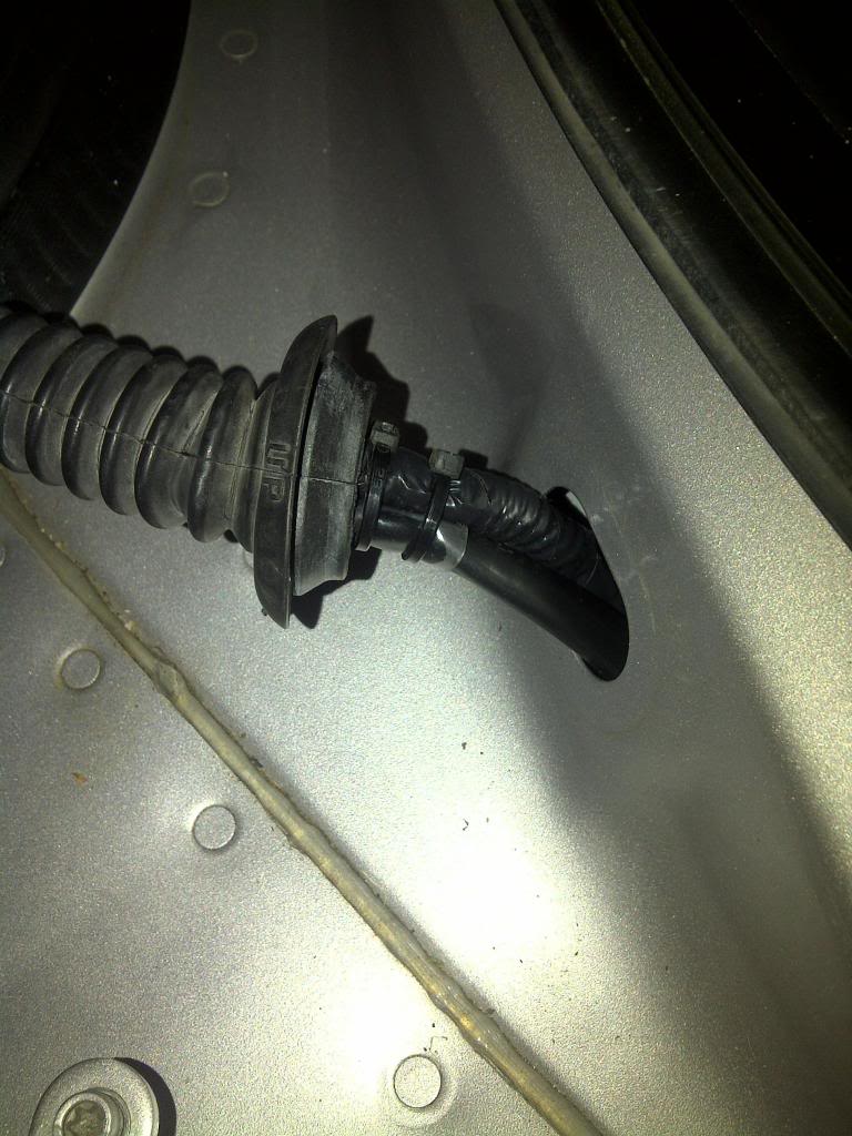
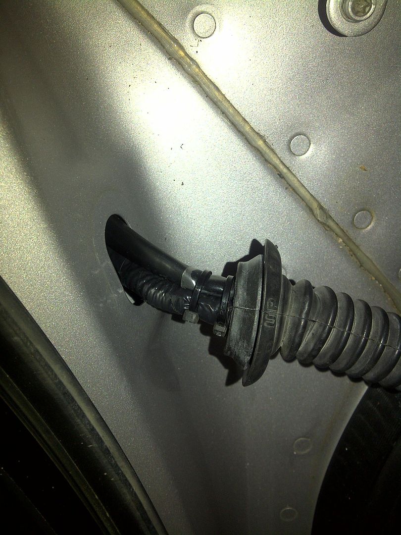
This is where it goes through the rubber link from the boot lid to the body
You will notice the clear heat shrink. I removed the other cover, so the power and video cables are separated inside the ribber. This was to make it more flexible.
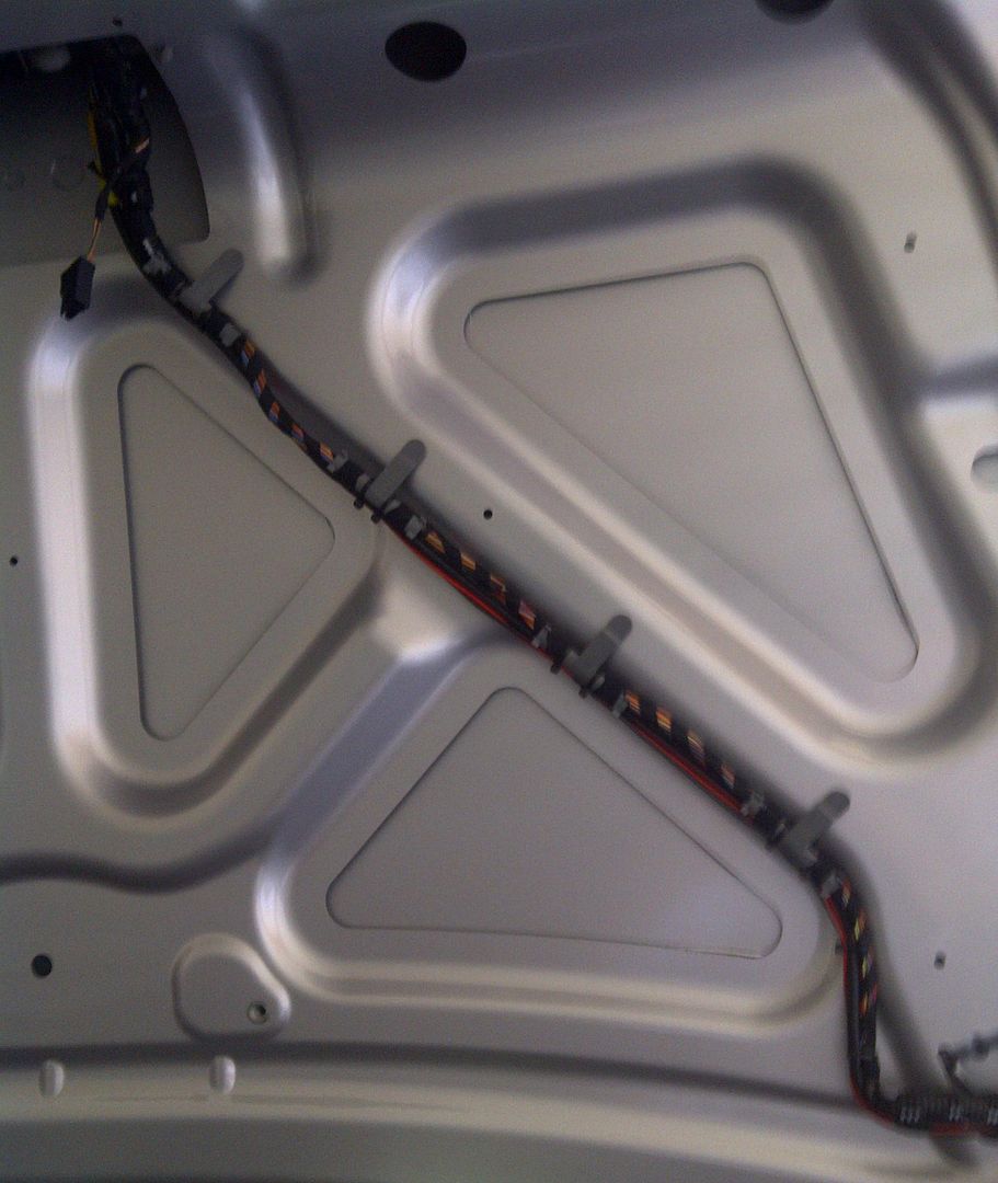
Here is the cable running around the boot area to where the nav unit is
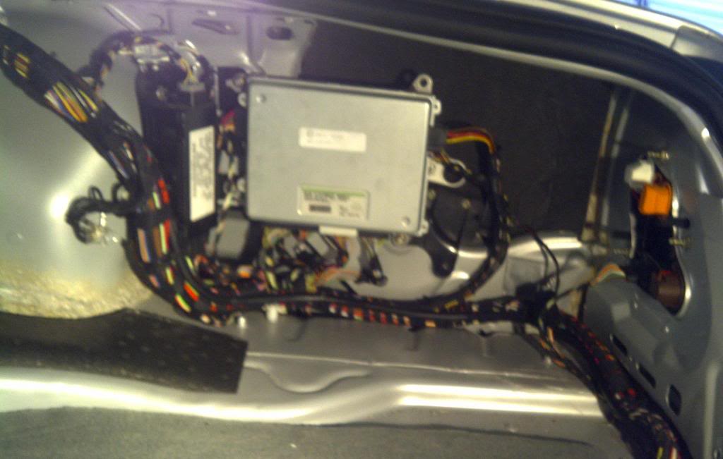
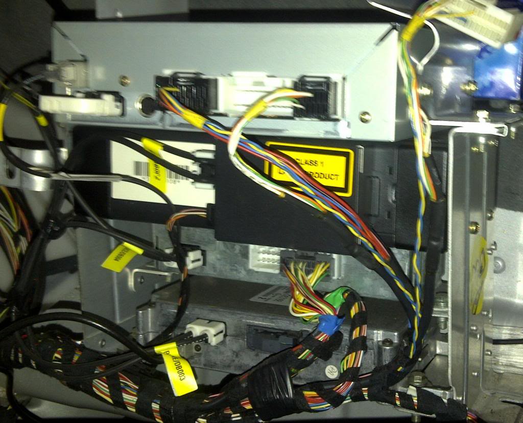
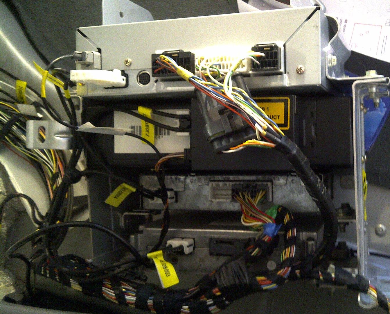
This is the back of the Audio rack in the boot.
The Denso Nav is on the top, The Plug that is removed is the one that has the RGBS signals need for a video interface..
You can also see i have removed some of the fabric loom
I have already removed the old video interface and returned the loom to factory at this point. The old one was mounted on the side of the rack and the signals tapped further down the loom
Here it is again with the loom stripped back. Just cut on end and unwind.
You can see the plug has 2 cables the larger one has the signal we need.
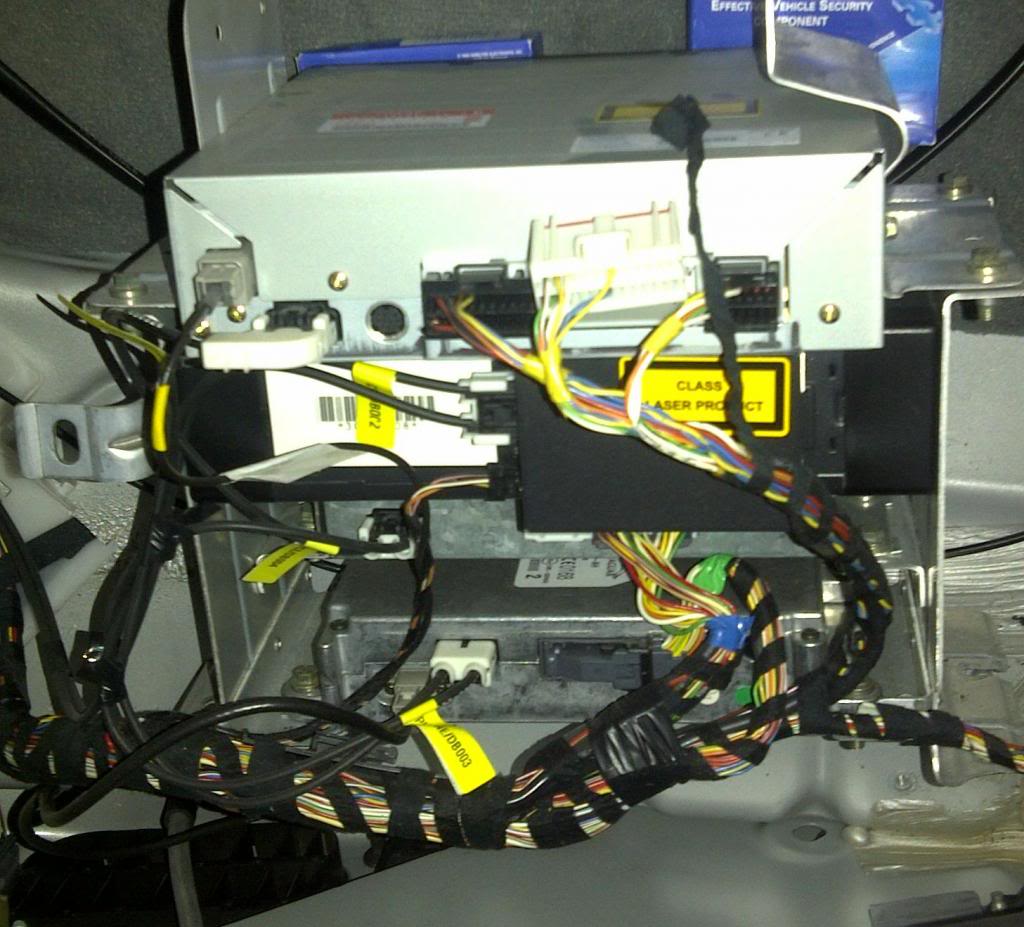
I have cut this cable (all 6 wires) and inserted a waterproof automotive plug/socket
The reason for this is so the system can be returned to standard at any time
In the Pic below you can see the plug/socket inserted into the system.
Here is a link to the plugs
Automotive Waterproof Plug & Socket Set - 6 way - Jaycar Electronics
Although I purchased from another supplier, purchasing all the combos from 2-6 pins in boxes of 20. actually cost about the same a buying 1 at retail prices
At this point we tested all was working and the video had all the correct colors

This plug/socket will be split and a loom created for the video interface.
I'll use another plug and socket on the loom having these go to the RGB out and RGB (oem) input.
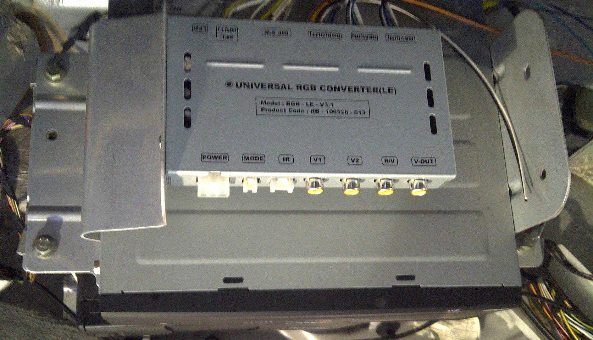
Here is a pic of the video interface mounted above the Nav unit.
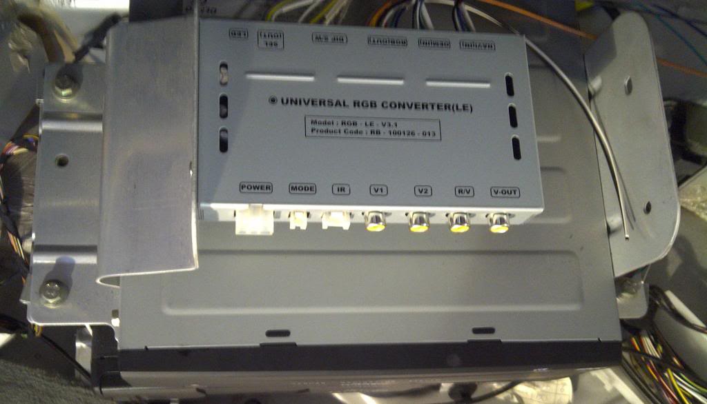
This is only temporary. I'm bending up some alloy stock to make a bracket.
This will also have the camera switch and pulse relays mounted to it
The Camera switch switches the signal to the R/V (Reverse) input between the side and rear cameras
The pulse relays detect the turn and rev signals going low and switch on for a preset time
For the side cameras this gets around the light flashing which would turn the camera on/off. It also gets around the negative trigger
We got into stripping the interior next taking out the seats, stripping the console, dashboard, rear seats, rear shelf and the covers around the doors.
It was at this point I had to rush off (see previous post)
More to come
Cheers
34by151
Picture links are here
http://s1305.beta.photobucket.com/user/34by151/library/
Rear Camera
You will notice only one cable. I used a cable that has a combined RG59 and power.
RG59 / Power Cable - Jaycar Electronics
This is where it goes through the rubber link from the boot lid to the body
You will notice the clear heat shrink. I removed the other cover, so the power and video cables are separated inside the ribber. This was to make it more flexible.
Here is the cable running around the boot area to where the nav unit is
This is the back of the Audio rack in the boot.
The Denso Nav is on the top, The Plug that is removed is the one that has the RGBS signals need for a video interface..
You can also see i have removed some of the fabric loom
I have already removed the old video interface and returned the loom to factory at this point. The old one was mounted on the side of the rack and the signals tapped further down the loom
Here it is again with the loom stripped back. Just cut on end and unwind.
You can see the plug has 2 cables the larger one has the signal we need.
I have cut this cable (all 6 wires) and inserted a waterproof automotive plug/socket
The reason for this is so the system can be returned to standard at any time
In the Pic below you can see the plug/socket inserted into the system.
Here is a link to the plugs
Automotive Waterproof Plug & Socket Set - 6 way - Jaycar Electronics
Although I purchased from another supplier, purchasing all the combos from 2-6 pins in boxes of 20. actually cost about the same a buying 1 at retail prices
At this point we tested all was working and the video had all the correct colors
This plug/socket will be split and a loom created for the video interface.
I'll use another plug and socket on the loom having these go to the RGB out and RGB (oem) input.
Here is a pic of the video interface mounted above the Nav unit.
This is only temporary. I'm bending up some alloy stock to make a bracket.
This will also have the camera switch and pulse relays mounted to it
The Camera switch switches the signal to the R/V (Reverse) input between the side and rear cameras
The pulse relays detect the turn and rev signals going low and switch on for a preset time
For the side cameras this gets around the light flashing which would turn the camera on/off. It also gets around the negative trigger
We got into stripping the interior next taking out the seats, stripping the console, dashboard, rear seats, rear shelf and the covers around the doors.
It was at this point I had to rush off (see previous post)
More to come
Cheers
34by151
Last edited by 34by151; Oct 29, 2012 at 03:31 AM.
Thread Starter
|
Veteran Member
Joined: Jan 2012
Posts: 1,174
Likes: 743
From: Sunshine Coast QLD
Done some more work. but the XJR is still apart in the hangar though
Getting really sick of driving the wife�s Merc.
Rear and side Cameras are wired up. Made a slight change to the side camera circuit.
Side cameras are now disabled when in reverse and speed is under 20kph
Taken the signal from the parking module speed disable to do that.
This is so the side cameras don�t come on when sitting at the lights, just want them for lane change blind spot detection
I also took the rear console home and have removed the rear audio panel. Hoping to fit the 7in screen in its place from home.
With luck final reassembly of the interior this weekend, just waiting on the confirmation of some extra hangar space over he weekend
Cheers
34by151

 thats a compliment.
Thread Starter
|
Veteran Member
Joined: Jan 2012
Posts: 1,174
Likes: 743
From: Sunshine Coast QLD
Finished off the side camera�s today
Here is the camera installed in the mirror taken before the mirror was put back on.
Camera is on the right, but not aligned, just mounted
The puddle lamp is still off so you can see the cable route
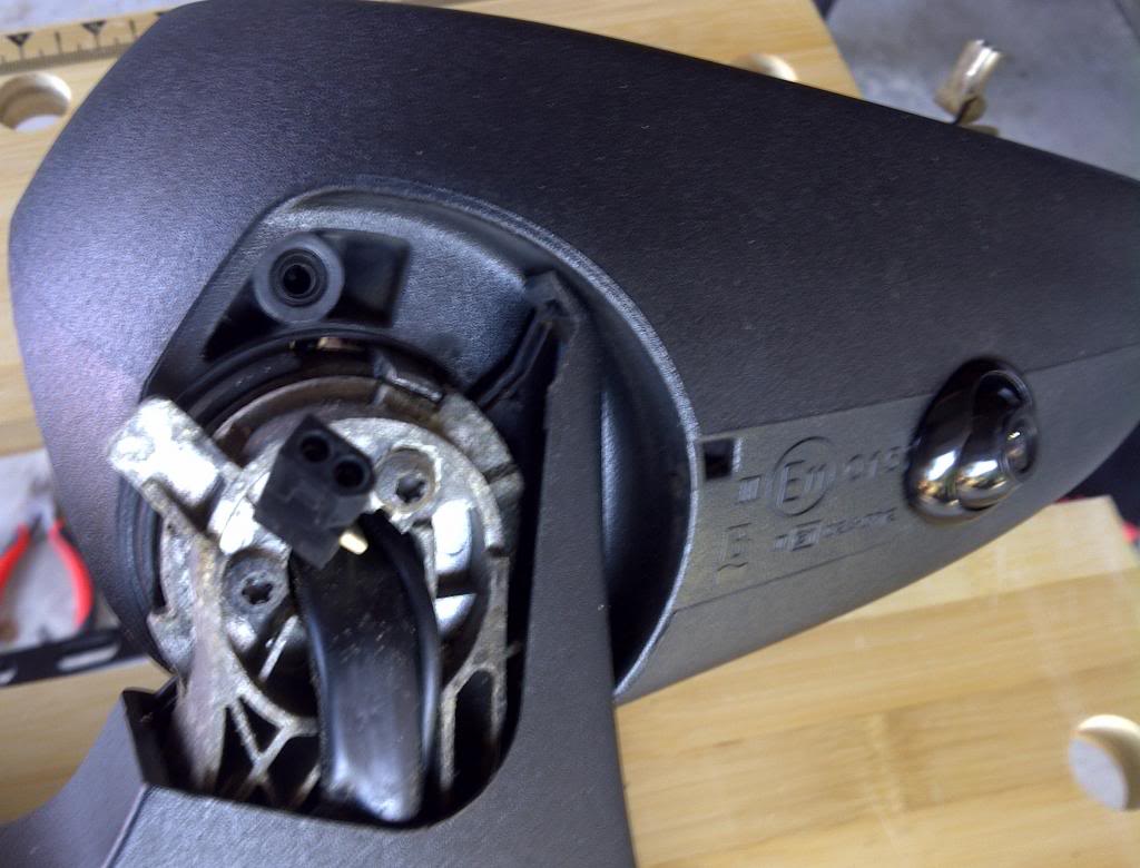
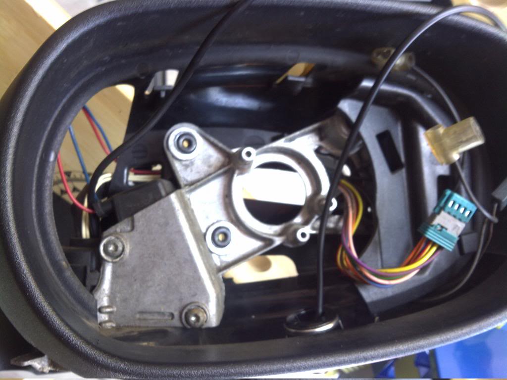
Here it is before i pulled the wire through all the way
The motor is also removed to make routing the cable easier
Installing the side cameras in the mirrors is quite easy here are the steps
1. Remove the outer door trim
2. Push the mirror all the way back (so you can get the puddle lamp out)
3. Remove the mirror trim and unbolt the mirror
4. Remove the mirror glass
5. Remove the back cover
6. Remove the motor
7. Remove the puddle lamp cover
8. Disconnect the puddle lamp, you need to pull up the plug that is hidden in the pivot
9. Drill the hole for the camera and mount the camera
10. Route the cable behind the motor and push through the pivot with the other wires
11. Put it all back together and mount the mirror
12. Remove the inner door trim
13. Remove the kick panel trim
14. Push a cable through the rubber between the door and body
Note: I uses a push pull cable for a remote control plane to do this
Also in the drivers side you need to remove the fuse box
Now you can run the wire to the video interface
For me I have run 6 coax leads from the boot to behind the glove box.
2 of these are for the side cameras and the rest for the RGBS from the new nav unit that is going behind the glove box with the acm
More as things progress
Cheers
35by151
Here is the camera installed in the mirror taken before the mirror was put back on.
Camera is on the right, but not aligned, just mounted
The puddle lamp is still off so you can see the cable route
Here it is before i pulled the wire through all the way
The motor is also removed to make routing the cable easier
Installing the side cameras in the mirrors is quite easy here are the steps
1. Remove the outer door trim
2. Push the mirror all the way back (so you can get the puddle lamp out)
3. Remove the mirror trim and unbolt the mirror
4. Remove the mirror glass
5. Remove the back cover
6. Remove the motor
7. Remove the puddle lamp cover
8. Disconnect the puddle lamp, you need to pull up the plug that is hidden in the pivot
9. Drill the hole for the camera and mount the camera
10. Route the cable behind the motor and push through the pivot with the other wires
11. Put it all back together and mount the mirror
12. Remove the inner door trim
13. Remove the kick panel trim
14. Push a cable through the rubber between the door and body
Note: I uses a push pull cable for a remote control plane to do this
Also in the drivers side you need to remove the fuse box
Now you can run the wire to the video interface
For me I have run 6 coax leads from the boot to behind the glove box.
2 of these are for the side cameras and the rest for the RGBS from the new nav unit that is going behind the glove box with the acm
More as things progress
Cheers
35by151

Thread Starter
|
Veteran Member
Joined: Jan 2012
Posts: 1,174
Likes: 743
From: Sunshine Coast QLD
The holidays and some other issues have slowed me up a bit.
I managed to get all the cables run and the interior reassembled so I can at least drive it again.
I had to redesign some of the interface due to how the touch screen interface works
Most and by that that I mean 99.9% of head units will have a touch membrane between the lcd and glass. Our units do not have this they have a matrix of IR led's. Thi is mounted in the bezel that houses the switches
This in itself is not a problem as fitting a touch membrane is easy.
The new membrane runs off to the interface that controls the new nav
The interface also controls the video interface switching the displays
So on power up, I can elect which display to have. IE Std Nav or the new one
To switch to climate, audio ect i just press the climate/audio button ect
Most people elect to have an external switch for the video interface. I have a virtual the touch interface can have virtual switches programmed. I press and hold the top right of the screen which sends the signal to the video interface to switch back to the OEM mode. This allows switching back to climate.
You are best to read the manual for the touch and video interfaces here for the full details
Multifunctional Universal Touch Screen Controller TSC-206IM. Car Solutions Online Store
DTI-M System Interface Controller. Car Solutions Online Store
Cable for TSC-206IM Connection to SerPro System Interface Controller. Car Solutions Online Store
IR Receiver for TSC-206IM Touch Screen Controller. Car Solutions Online Store
Universal RGB Low-End Car Video Interface. Car Solutions Online Store
I have been working on interfacing the headunit, camera's and nav further over the holidays
I have finished prototyping a micro controller to control these things better
To do this I'm using a Ardunio Eleven and a Joycon interface
I could do without the joycon but why reinvent the wheel when I can just but the part
The Joycon is here
RcJoyCon - Control Car PC with Steering wheel controls
This has the ability to connect to 4 resistive switch networks and output keystrokes via usb emulating a keyboard. You can also control 2 led's, more on that in a sec
Channel A is connected to the steering wheel audio controls
The usb is connected to the new nav unit
The nav sees the joycon as a HID keyboard
Pushing Track up or down on the stering wheel send the keyboard codes for track up and down to the nav. This changes track on the media player
PS this also works for android phones
Channel B is connected to the turn signals
Left turn enables led1
Right Turn enables led2
Hazzard does nothing
Ok so onto the micro controller. I'm using the Arduino Eleven
Parts & Kits for Arduino Online, Buy Microcontroller Boards, Electronic Components for Arduino - Eleven (100% Arduino Uno Compatible) - Freetronics
For the purposes of rapid prototyping I'm also using the Terminal shield
Parts & Kits for Arduino Online, Buy Microcontroller Boards, Electronic Components for Arduino - Terminal Shield for Arduino - Freetronics
And the relay shield
Parts & Kits for Arduino Online, Buy Microcontroller Boards, Electronic Components for Arduino - RELAY8: 8-Channel Relay Driver Shield - Freetronics
Once I have finished the code I will remove the 2 shields and solder the needed parts to the prototyping area of the eleven
Here is what I have working so far
Pin D12 connects to the video interface input select
Pin D11 connects to the video interface left camera select
Pin D10 connects to the video interface right camera select
Pins D0 and D1 connects to the LED output from the Joycon
Pins D2 and D3 connects to the Drive door switch pack, pins DD12-3 and DD12-2 on the Driver door module. (see page 10.2 in the XJ electrical manual)
Pin D4 Connects to Roof console parking aid switch, pin CR52-7 on the parking aid module (see page 18.1 in the XJ electrical manual)
Pin D5 connects to chime inhibit on the parking aid modules pin CR52-6 (see page 18.1 in the XJ electiclal manual)
Pins D6, 7 and 8 connect to the head unit more on that in a sec
Here is what I have working
Cameras
1.Reverse selects the rear camera
2. Selecting Left turn tuns on LED1 on the Joycon
This triggers the Audrino to send pin D11 high turning on the left camera
This stops when the turn signal stops and does not suffer from flashing by using the lamp as the trigger
3. Selecting Right turn tuns on LED2 on the Joycon
This triggers the Audrino to send pin D10 high turning on the right camera
This stops when the turn signal stops and does not suffer from flashing by using the lamp as the trigger
4. Selecting the left mirror adjust on the drivers door turns on the left camera. This is the center off switch not the motor switch. This is handy for parking or checking out the bind spots. When the switch is selected it sends pin D2 low which sends pin D11 high turn on the left camera on the video interface
5. Selecting the right mirror adjust on the drivers door turns on the right camera. This is the center off switch not the motor switch. This is handy for parking or checking out the bind spots. When the switch is selected it sends pin D3 low which sends pin D10 high turn on the right camera on the video interface
6. Camera on/Off
When you press the parking aid disable switch on the roof console this will send pin D4 low. This tells the arduino code not to turn on any camera. IE it disables the left/right cameras. With this pin grounded pins D10 and D11 will never go high
7. Camera speed control
Pin D5 functions in a similar way to the camera on/off function. This uses the chime inhibit signal from the parking aid module. This signal disables the parking aid speaker when you are going over 10kph/6mph. When this signal is on, the turn signals no longer turn on the cameras. Using the mirror switch still tuns them on (as per 2 and 3) unless the disable is selected (as per 6). I have done this so the cameras are not on when sitting at the light waiting to turn. I just want them for lane change bind spots.
What I'm working on now
Pins D6, D7, D8 is connected to the head unit
Pin D6 connects to the Audio Button
Pin D7 connects to the Phone Button
Pin D8 Connects to the Climate Button
Pin D9 Connects to the Nav button
Pin A0 Connects to the video interface
As the video interface intercepts the video signal, pressing Audio, Phone or Climate will still have the aux video on the screen. You need to turn off the aux video
Pressing Audio will send pin D6 low
Pressing Phone will send pin D7 low
Pressing Climate will send pin D8 low
When Pins D6, D7 or D8 go low the Ardunio will pulse pin D12 low.
This cycles the video interface From OEM Nav (the one we want) to RGB (ny new nav) , Video 1 then Video2.
The video interface has an output signal when each of these are selected. I have set these up using a resistive network which i the same as the streeing wheel controls work.
In other words the voltage changes depending on which video input is selected.
This signal is connected to the Ardunio on pin A0. The Ardunio will keep pulsing pin D12 low till the OEM nav is selected. Before this happens I store the value of the pin A0 for latter use
So pressing Audio, Climate or phone will turn off the aux video and show you what you selected
Now if you press Nav pin D9 will trigger. The Ardunio will read the stored value for pin D12 and restore the aux input you were using (OEM nav, My nav, Video 1 or 2)
I have this code working on the bench and will upload to the Ardunio in the car soon.
What I'm finishing off is one more function for the nav button
I'm working on each press of the nav button will also cycle through the video inputs. IE Oem nav, My Nav, Video 1, Video 2
Its proving a bit trick to get the code right with the above functions for climate, phone and audio. Hope to be there soon
I will be happy to publish the code and diagrams once i'm finished. You wont need any electronics knowledge to follow my setup. The Ardunio code is upload to the Ardunio via usb and the rest is just running wires.
I'm waiting for a touch membrane to ship for my head unit. I'll publish pics of that install and connecting to the head unit switches once that arrives and I do the install
Cheers
34by151
Some Pics of the work so far
Picture links are here
34by151's Library | Photobucket
Rear Camera
You will notice only one cable. I used a cable that has a combined RG59 and power.
RG59 / Power Cable - Jaycar Electronics
This is where it goes through the rubber link from the boot lid to the body
You will notice the clear heat shrink. I removed the other cover, so the power and video cables are separated inside the ribber. This was to make it more flexible.
Here is the cable running around the boot area to where the nav unit is

This is the back of the Audio rack in the boot.
The Denso Nav is on the top, The Plug that is removed is the one that has the RGBS signals need for a video interface..
You can also see i have removed some of the fabric loom
I have already removed the old video interface and returned the loom to factory at this point. The old one was mounted on the side of the rack and the signals tapped further down the loom

Here it is again with the loom stripped back. Just cut on end and unwind.
You can see the plug has 2 cables the larger one has the signal we need.
I have cut this cable (all 6 wires) and inserted a waterproof automotive plug/socket
The reason for this is so the system can be returned to standard at any time

In the Pic below you can see the plug/socket inserted into the system.
Here is a link to the plugs
Automotive Waterproof Plug & Socket Set - 6 way - Jaycar Electronics
Although I purchased from another supplier, purchasing all the combos from 2-6 pins in boxes of 20. actually cost about the same a buying 1 at retail prices
At this point we tested all was working and the video had all the correct colors
This plug/socket will be split and a loom created for the video interface.
I'll use another plug and socket on the loom having these go to the RGB out and RGB (oem) input.
Here is a pic of the video interface mounted above the Nav unit.
This is only temporary. I'm bending up some alloy stock to make a bracket.
This will also have the camera switch and pulse relays mounted to it
The Camera switch switches the signal to the R/V (Reverse) input between the side and rear cameras
The pulse relays detect the turn and rev signals going low and switch on for a preset time
For the side cameras this gets around the light flashing which would turn the camera on/off. It also gets around the negative trigger
We got into stripping the interior next taking out the seats, stripping the console, dashboard, rear seats, rear shelf and the covers around the doors.
It was at this point I had to rush off (see previous post)
More to come
Cheers
34by151
Picture links are here
34by151's Library | Photobucket
Rear Camera
You will notice only one cable. I used a cable that has a combined RG59 and power.
RG59 / Power Cable - Jaycar Electronics
This is where it goes through the rubber link from the boot lid to the body
You will notice the clear heat shrink. I removed the other cover, so the power and video cables are separated inside the ribber. This was to make it more flexible.
Here is the cable running around the boot area to where the nav unit is
This is the back of the Audio rack in the boot.
The Denso Nav is on the top, The Plug that is removed is the one that has the RGBS signals need for a video interface..
You can also see i have removed some of the fabric loom
I have already removed the old video interface and returned the loom to factory at this point. The old one was mounted on the side of the rack and the signals tapped further down the loom
Here it is again with the loom stripped back. Just cut on end and unwind.
You can see the plug has 2 cables the larger one has the signal we need.
I have cut this cable (all 6 wires) and inserted a waterproof automotive plug/socket
The reason for this is so the system can be returned to standard at any time
In the Pic below you can see the plug/socket inserted into the system.
Here is a link to the plugs
Automotive Waterproof Plug & Socket Set - 6 way - Jaycar Electronics
Although I purchased from another supplier, purchasing all the combos from 2-6 pins in boxes of 20. actually cost about the same a buying 1 at retail prices
At this point we tested all was working and the video had all the correct colors
This plug/socket will be split and a loom created for the video interface.
I'll use another plug and socket on the loom having these go to the RGB out and RGB (oem) input.
Here is a pic of the video interface mounted above the Nav unit.
This is only temporary. I'm bending up some alloy stock to make a bracket.
This will also have the camera switch and pulse relays mounted to it
The Camera switch switches the signal to the R/V (Reverse) input between the side and rear cameras
The pulse relays detect the turn and rev signals going low and switch on for a preset time
For the side cameras this gets around the light flashing which would turn the camera on/off. It also gets around the negative trigger
We got into stripping the interior next taking out the seats, stripping the console, dashboard, rear seats, rear shelf and the covers around the doors.
It was at this point I had to rush off (see previous post)
More to come
Cheers
34by151
Hate to admit it, but as for now, I've seem to say "oh well" on my Video interface install due to the fact,,,,,, I'm afraid to remove the backseat to run the video switch &/or any other cables from the trunk to the front of the car.
I'm not so worried @all with the interface & Tronsmart install, it's just getting the Switch & IR extender (if I need one) in the front...
I'm not so worried @all with the interface & Tronsmart install, it's just getting the Switch & IR extender (if I need one) in the front...
Last edited by Marque; Mar 18, 2015 at 01:04 PM.
Thread Starter
|
Veteran Member
Joined: Jan 2012
Posts: 1,174
Likes: 743
From: Sunshine Coast QLD
The cable run is an easy job
You will need to remove the rear seat and the trims in the boot
You needed to remove the trims anyway for the interface install
The rear seat is easy once you have done it once
The trick is to work from one side, pushing the release levers as you go
I put a screwdriver under the fist lever to prevent it catching again as I move to the next one
For the cables, follow the main harness from the nav to the cabin
It will pass through a large whit gland that has plenty of space for cables
I ran a 12 core data and 6 coax cables (2 * 3 way cables) though with room to spare
Once in cabin follow the harness to the center of the seat and run down beside the console. To pass the cables under the carpet use a snake. I use a section of yellow tongue to do this.
Once under the console its an easy straight run to the head unit
I terminated the data cable with a plug under the head unit (behind the ashtray)
One 3 core coax runs under the steering wheel to the panel that unscrews (for access to the steering column). This is where my android unit is mounted
Once of the cores from the second cable runs here as well. This provides the RGBS to the interface from the android unit
The second 3 core coax goes to behind the glovebox. I have the ACM aux input in the glovebox so one of the cores is used for a video in socket next to the acm. The last core core is used for the side cameras. The switching between Left/Right camera is done behind the glovebox.
Cheers
34by151