When you click on links to various merchants on this site and make a purchase, this can result in this site earning a commission. Affiliate programs and affiliations include, but are not limited to, the eBay Partner Network.
F type seats- Wiring diagrams or wiring recommendations
Hi,
I was wondering if anyone could help direct me into getting some 2018 f type leather/alcantara seats into my Aston Martin vantage.
I know the looms won�t match up so I am looking to understand the function of the seat wires so that I may construct a separate button control console.
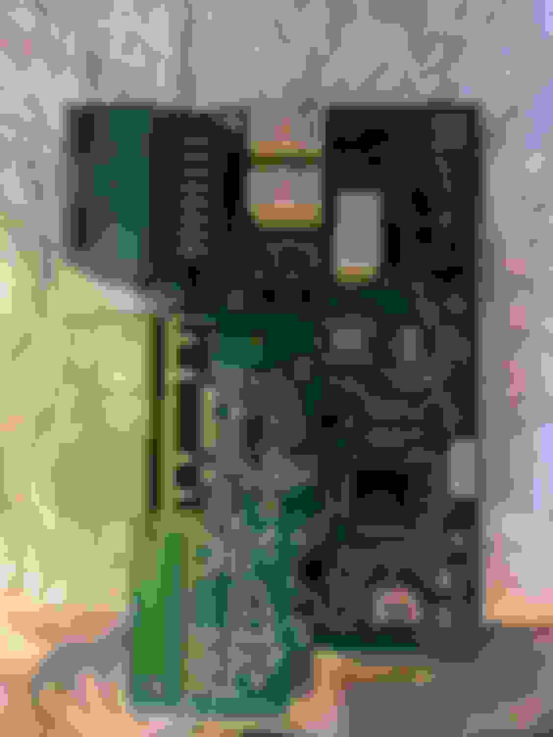
Would anyone be able direct me towards any 2018 wiring diagrams, for the model numbers in the photos below? Seat model as we as seat circuit board I am supposing this is where the seat connects to the cars original loom The circuit board under the seat The two clips that plug into the circuit board under the seat Side view of the base
Here are two docs you can use on my shared drive. One is the Wiring Diagram for the Seat Heater Wiring. The other is ~400 Page PDF on all aspects of the seats. in the F-Type. I put them there temporarily so download them as I will delete them at some point.
Here are two docs you can use on my shared drive. One is the Wiring Diagram for the Seat Heater Wiring. The other is ~400 Page PDF on all aspects of the seats. in the F-Type. I put them there temporarily so download them as I will delete them at some point.
You might take a look in the workshop manual, under Body, Seating. It discusses a number of topics, including airbags. Note there are two styles of seats, Sport and Performance.
Good luck! Should be a fun project if you can make it work.
I currently have a sim rig with a solid start mover but I'll go over the weight limit with this start (and my ample belly). My plan is to switch the motion out to a 4 point system that moves the whole rig and can handle my weight with this seat.
I've been through the wiring diagrams, and tried to find info in that massive manual and see that it should be pretty reasonable to wire up, but am missing a drawing or something which tells me which pins are which.
I've been through the wiring diagrams, and tried to find info in that massive manual and see that it should be pretty reasonable to wire up, but am missing a drawing or something which tells me which pins are which.
(I didn't mean to post already)
4 pins on the switch pack. I don't know which side is pin 1. Can someone help me out?
I have a 360W 12V power supply on the way and expect to connect it to pin 1 when I figure that out and to the control module. From what I gather, is just those 2 points, yeah?
I spent a while going through the wiring diagrams for the whole car (I'm a retired EE). First, here are a few more documents, which won't help you much.
This one defines what all the abbreviations mean on the wiring diagram. Unfortunately, it describes how to use their online system to get face views of connectors to view pinouts. I don't have access to that, and don't recall seeing those. https://www.dropbox.com/s/x26e91fmqu...ns%20.pdf?dl=0
This one has a map of all the vehicle networks in the car (which is pretty out-of-control.) It shows that the door switchpacks connect directly to the seat controllers via a dedicated LIN link (a digital data bus.) That's good. It also shows that the seat controllers are on a MS CAN (medium-speed CAN bus, a different digital data bus) along with a number of other modules. Whether the seat module will work without the rest of the car on the MS CAN, I have no idea. https://www.dropbox.com/s/e6fp29b26h...works.pdf?dl=0
The wire 'LOGIC FEED' is simply the battery voltage, via a lower-amperage fuse than other things. In your application, you can tie the various VBATT, LOGIC FEED, 12V etc together to your power supply. And tie all the grounds together.
'LIN' should be a direct connection from the door switchpack to the seat controller. It isn't shown as a twisted pair, as most of the data busses are.
The wiring diagram is for LHD and uses 'right' and 'left'. The network diagram uses driver (DSM, Driver Seat Module), and passenger (PSM). While the network diagram shows the driver switchpack LIN connecting only to the driver seat controller, the wiring diagram shows the driver's side LIN also connects to some of the climate control stuff.
You may ultimately find that you can't make the switchpack and controller work together. If not, the last resort would probably be to remove the seat controller and come up with some higher-current switches to directly switch 12V into the seat motors. You'd lose the position sensors that stop the motors at the limits, so you'd have to be careful, presumably.
Left is power, right is small signal. Small signal, 22 pin, I believe. 12 pin power.
Great, are the connectors the same type of metal?
Mixing metals can cause corrosion, Lotus mixed the metal on the engine harness connectors and had all kinds of issues. Don't want you to see the same type of issues down the road.
Great, are the connectors the same type of metal?
Mixing metals can cause corrosion, Lotus mixed the metal on the engine harness connectors and had all kinds of issues. Don't want you to see the same type of issues down the road.
Thanks for the thought! I did all the small signal stuff with mechanical connectors and heat shrink to hold them together. I used a power cord for the others and soldered them.
I'll keep that in mind if I run into trouble. If so, I'll just switch power over to mechanical connections too.
I forgot to mention about the lack of sensor. I cannot hold the switches. When I press one it just moves a bit, so I need to sorta push push push push...
But I'm ok with that. It stores memory settings but won't go all the because of the sensors. I was going it would work but no.