When you click on links to various merchants on this site and make a purchase, this can result in this site earning a commission. Affiliate programs and affiliations include, but are not limited to, the eBay Partner Network.
HELP: 2012 XJL power seat adjusts in pulses and not smooth
I have the seats from a 2012 XJL and was able to get my wiring setup working through the power seat module, but when I try to adjust the seat in any way it only allows me to adjust it in pulses and not continuous power feed as I hold down or push on the seat adjustment switch. Do let me know if this is by design and that there is nothing I can do. BTW, I subscribed to ALLDATADIY.com to get the power module pin connection layout which helped out.
guanshee, I wrote you an answer to the PM that you sent me. Seeing this, I see your problem very clearly now. In short, the seat module needs a connection to the CAN bus of the car to operate things. Since your MK2 does not have a CAN bus, this is not connected. This puts the seat module into what is referred to as "inch mode". So, if the button is pressed for more than 2 seconds, it will cause the seat to move slightly, then stop. Unfortunately, there isn't a lot of fix for this unless you transfer the whole CAN bus network over to the MK2. Maybe by chance there is some gizmo out there that can simulate the CAN bus and trick the seat module, but I am not holding my breathe as it would need to be fairly specific to the application.
guanshee, unfortunately, the easiest answer I see to get smooth operation is to "rebuild" the switch panel on the side of the seat using DPDT switches that are rated for 20 amps (10 amp ones may work). Then you would need to rewire the seat, bypassing the computer all together.
If you need me to give you more detail on this, then let me know and we can take things from there.
Thermo thanks for the update and I believe you are right in that I will need to re-wire the setup with a different set of switches. Do let me know what items I need to get and the wiring mapping. BTW, my power seat module is the 18+-way seat adjustment.
guanshee, in short, you are going to need a DPDT switch for each of the functions on the seat. The switch is going to get wired up using this setup:
Then it is a matter of finding the wire pairs for each motor and wiring them to the switch (ie, the green wires on the center posts). How you orientate the switches to know what each function is, that will take a little thought on your part. You will also want to use momentary switches (ie, those that return to center when released). This will prevent you from accidentally hitting a switch and having the seat drive you all the way into the steering wheel or pull you away from it. Driving down the road, I think you can see where that might be bad. I would also recommend that you turn some of the switches 90 degrees so the switch moves in the direction that the seat is going to move. So, the raising of the front of the seat would have the switching being vertical so lifting up on the switch would cause the seat to go up. But, you would turn the switch 90 degrees for moving the seat forwards and backwards.
This is where you may also find it helpful to have a common point that you can get the power from (say a terminal strip) so you can take a single power source and split it into the 8 different power wires (1 for each switch). Otherwise, you are going to have to run a jumper wire from 1 switch to the next, to the next, ..... This can be difficult as you will have to run large gauge wire to handle the current draw if you plan on running multiple motors at the same time. Where the terminal strip will have you running a single large wire to the strip and then installing a jumper bar to short multiple terminals together. That will give you multiple outputs for the switches. You can run say 2 wires off of each spot on the terminal strip. You can do the same with the ground wires to keep things consistent. It will also make it easy for future removal of the seat as then you will only need to disconnect 2 wires and the seat will come out. If you want to make it so the seat only moves when there is power to the car, I can show you how to do that too. In short, you are taking a relay and wiring up the control side of the relay to a switchable 12 VDC source and the power side can be run to a constant 12 VDC source. That way, should there be a problem with the seat, it will not kill the battery.
As I try to get the inventory of items you noted in your last message, do you happen to know or determine the CAN BUS message that needs to be sent to the power seat module to have it behave normal as I can possibly sniff and send messages to the CAN BUS wires of the power seat control module? I was thinking of connecting an Arduino to the 2 CAN BUS wires on the seat module for me to push the required message. Just a thought.
guanshee, when it comes to the CAN Bus, this is where I am no help. This is one of the areas that I have never played and anything I would be saying would be something that I am pulling out of a deep, dark, spot. So, this is where some homework may be needed to figure that out.
I've got all the wires that adjust the seats identified and tested. What I can't seem to find and test is the lumbar support wiring and how to setup a test. I see under the seat lumbar pump with 2 wires connected to it. I noticed once I have power to the power seat control module and apply a ground probe on the white/orange wire connected to the pump , I can hear the pump running. Can you elaborate on the wire setup to test it? Again I have the 20-way seat control module.
guanshee, the trick with the lumbar pump is that you need to activate the bladder solenoid that you want to fill/drain the appropriate bladder. If you look at the seat, you may be able to see where you have an upper and lower bladder. This may take a little bit of playing too.
I am going to try and make this as simple as possible. If you look on the plug that you have the lumbar pump powered from, the lumbar pump power should be coming off of pin 19 (brown-green wire). If you look at PIns 17 and 18, you should see a gray-violet and a white green wire respectively. These are the power wires for the solenoids. The ground wires are attached to pins 5 and 6, brown-violet and yellow-violet wire respectively.
When you want to inflate the lumbar pillows, you need to run the pump and also energize one of the fill solenoids. To deflate the pillow, I believe you only need to energize the solenoid and the air will vent out.
As for wiring, keeping in mind which wire is positive/power and which is ground. The solenoids are activated using the following wires:
-upper pillow fill: white-green and yellow-violet
-upper pillow deflate: gray-violet and brown-violet
-lower pillow fill: white-green and brown-violet
-lower pillow deflate: gray-violet and yellow violet
How you wire it up, that will probably be the tricky part. I would need to sit down and think about things for a bit. My initial thought is you may need to get what is referred to as a TPDT (triple pole, double throw) switch. What this will allow you to do is ground the black wire coming off of the pump and then when you flip the switch to fill a pillow, you can wire it up so the solenoid will get power using 2 of the poles and the 3rd will be used to supply power to the pump. If I need to draw this out, let me know and I will see what I can do.
I have the seats from a 2012 XJL and was able to get my wiring setup working through the power seat module, but when I try to adjust the seat in any way it only allows me to adjust it in pulses and not continuous power feed as I hold down or push on the seat adjustment switch. Do let me know if this is by design and that there is nothing I can do. BTW, I subscribed to ALLDATADIY.com to get the power module pin connection layout which helped out.
BTW, I'm dropping these seats in a Jaguar Mk2.
Any information would be appreciated.
This sounds like a super cool build, MK2 with the luxury seats out of a XJL! If you could post some pics of this build I know I wouldn't be the only one that would love to see them!
guanshee, here is a diagram of what I am talking about. fairly simple to wire up. You will probably end up having two wires running from 2 switches to power the lumbar motor (one for the upper fill chambers, one for the lower fill chambers). It won't be a problem as the switches will not allow power to cross to something else.
You have 3 sets of contacts (each vertical row). You can think of the center as being the output for each contact with it seeking 1 of 2 power sources. In the case of the lumbar pump, it will only have one and the other will force it to be off. What this does is when you move the toggle up, pins 1 and 2, 4 and 5, and 7 and 8 make contact, sending power to the solenoids to fill and power to the pump to cause it to run. If you toggle down, then pins 2 and 3, 5 and 6, and 8 and 9 make contact. Pins 2 and 3 will not cause anything to happen, Pins 5 and 6 and 8 and 9 are going to reverse the polarity, causing your solenoids to now vent. This is where having the wiring for the solenoids is going to be critical. So, it may take a little bit of playing to make it work.
If you need me to explain things a bit more, let me know and I will see what I can do for you.
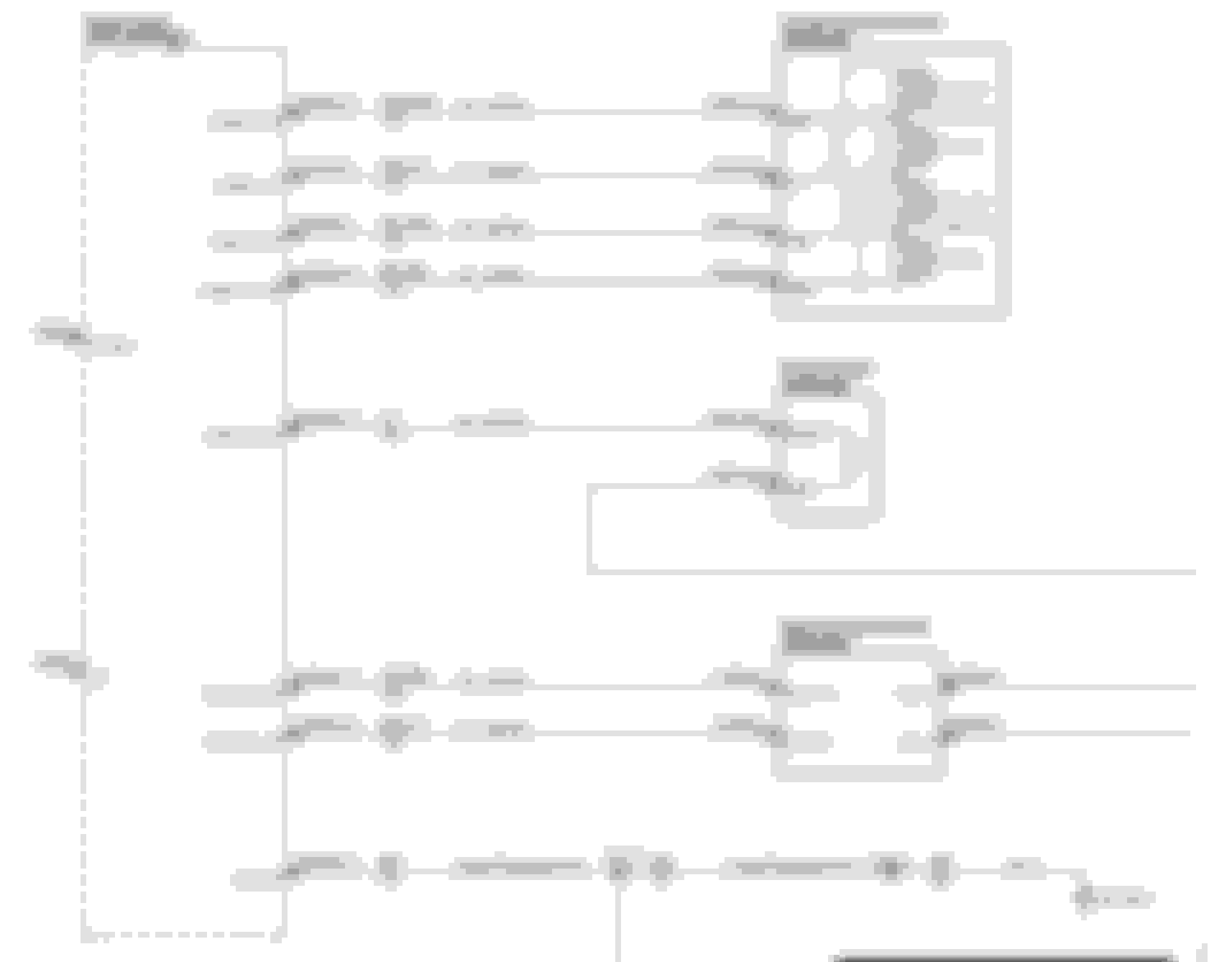
Thermo - I was able to setup a 3pdt switch to control the lumbar solenoid but am a little confused on the wiring setup based on the attached pic of the wiring diagram. Can you shed some light as to the pairing of wires to the 3pdt switch. I tested wiring WH_VT and WH_OG to the 3pdt switch and nothing happens. When I touch the terminals off-and-on I hear a silent click but that is it.
Last edited by guanshee; May 11, 2018 at 01:16 AM.
guanshee, let me get home and I will look at this again. My work computer restricts what I can look at. So, makes it difficult to give you an answer at the moment.
Thx. BTW, I checked on the Lumbar pump and noticed a VT and WH_OG wires connected to it. They appear to originate from the back of the seat. When I apply a ground directly to the WH_OG wire connector terminal which is directly connected to the pump I hear the pump kick-in and I checked the VT wire which appears to have a live 8+ volts running through it regardless if the VT wire to the switch-pack-seat-passenger is not connected to anything. I had tested applying a ground to the WH_OG wire noted in the diagram that connects to the switch-pack-seat-passenger connector thinking it would start the pump as well as I thought it was related due to being the same color, but nothing happened.
Last edited by guanshee; May 11, 2018 at 12:04 PM.
guanshee, based on the drawing that you supplied, I am going to need to redraw things. In short, you are going to have 2 switches from what I can tell. One is going to inflate/deflate the upper lumbar and the other switch is going to control the lower lumbar. I think the drawing that I was looking at had things wired a little differently.
In short, to make this circuit work for the 4 solenoids, you apply power to 1 wire, you ground a second and you leave the last 2 "disconnected" (the switch is going to open the wire, making it "disconnected"). This will activate a solenoid. In the case of this circuit, the white-orange and the blue-brown wires are your ground wires and the white-violet and the gray-orange wires are your power wires. Depending on which wire you apply power to and which one you ground will define which solenoid gets put into the circuit and works. Other solenoids may see the power or the ground, but they won't see both and therefore, will not function (no complete circuit).
Let me sit down and redraw this for you to make it a bit more logical and something that you can sit down and re-create.