When you click on links to various merchants on this site and make a purchase, this can result in this site earning a commission. Affiliate programs and affiliations include, but are not limited to, the eBay Partner Network.
Not sure if this was mentioned before, but a with tripped inertia switch, there will be no cranking action -- I think some of the only electric circuits allowed is like emergency flashers, if tripped.
Last edited by smartobject; Jun 15, 2018 at 01:36 PM.
You would have to accurately measure with a digital meter ( calibrated ? ) the voltage at the RH engine box terminal post to see if you are at this 11.4 volt point as some start attempts based on you battery charge state you may be on this side or that side of the 11.4 point .
On a personal note on M'Lady P the starter solenoid output terminal post was shorting to ground causing the voltage to drop to 9.5 volts which would rotate the starter but no light off . I developed a easy test for this point of failure without removing the starter assembly in the following link post # X .
You'll have to decide where you want to put your time and resources into any direction you go as I can't give you a percentage chance based on my experience as this is my first Jaguar and I didn't work in a automotive shop .
Just to check..last question before I go up in the morning. ..presumably the crank sensor is three wire? one wire being supply voltage ,and just to confirm, it's 5v not 12v .
Edit ..just seen it's two wire !! so there should be 5v ( not 12?) on one of those wires with the ignition on but not cranking ..or is it only when cranking?
Not sure if this was mentioned before, but a with tripped inertia switch, there will be no cranking action -- I think some of the only electric circuits allowed is like emergency flashers, if tripped.
100% False. Please delete this misleading post.
Tap Your switch with a screwdriver handle, then go start the car. Now try turning on the radio. Lights? Air Conditioning? Everything works except the car won�t turn over. She�ll crank forever, but she won�t turn over.
Just about to chk inertia, switch... Presumably its behind the kick panel on the outside face of the drivers footwell on UK car?
Just before that... Had ascertained that with existing battery installed and jumped of my van which had two batteries and an alternator the size of a small family car, with engine running, the jag still won't start... I'm increasingly convinced it's not the battery.
Uncoupled fuel line at injector rail... Fuel appears on cranking
Disconnected CKPS connector.... 2.25V ign on, not cranking.... Lady Penelope says this should be 5v... So... Now we're getting somewhere.
Fist question... If ECU wasn't switching on there'd presumably be 0v at CKPS?... So, is ECU firing up but there's a resistance somewhere in the supply?
Be careful of how you hook up jumper as it can harm the car if wrong even with the Jaguars battery hooked up being assisted
. History of that from others .
I made an error in one of my replays and double checking it .
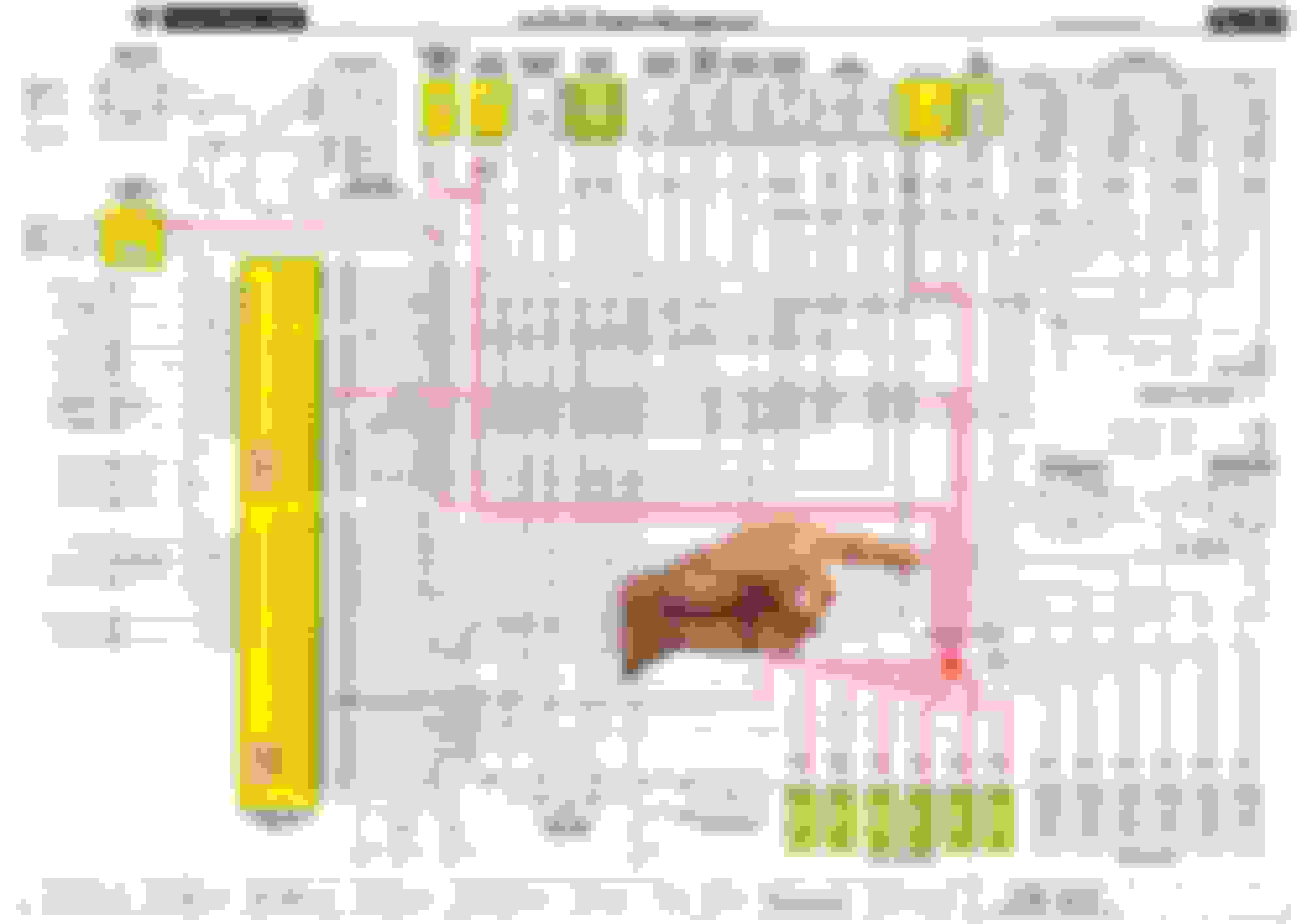
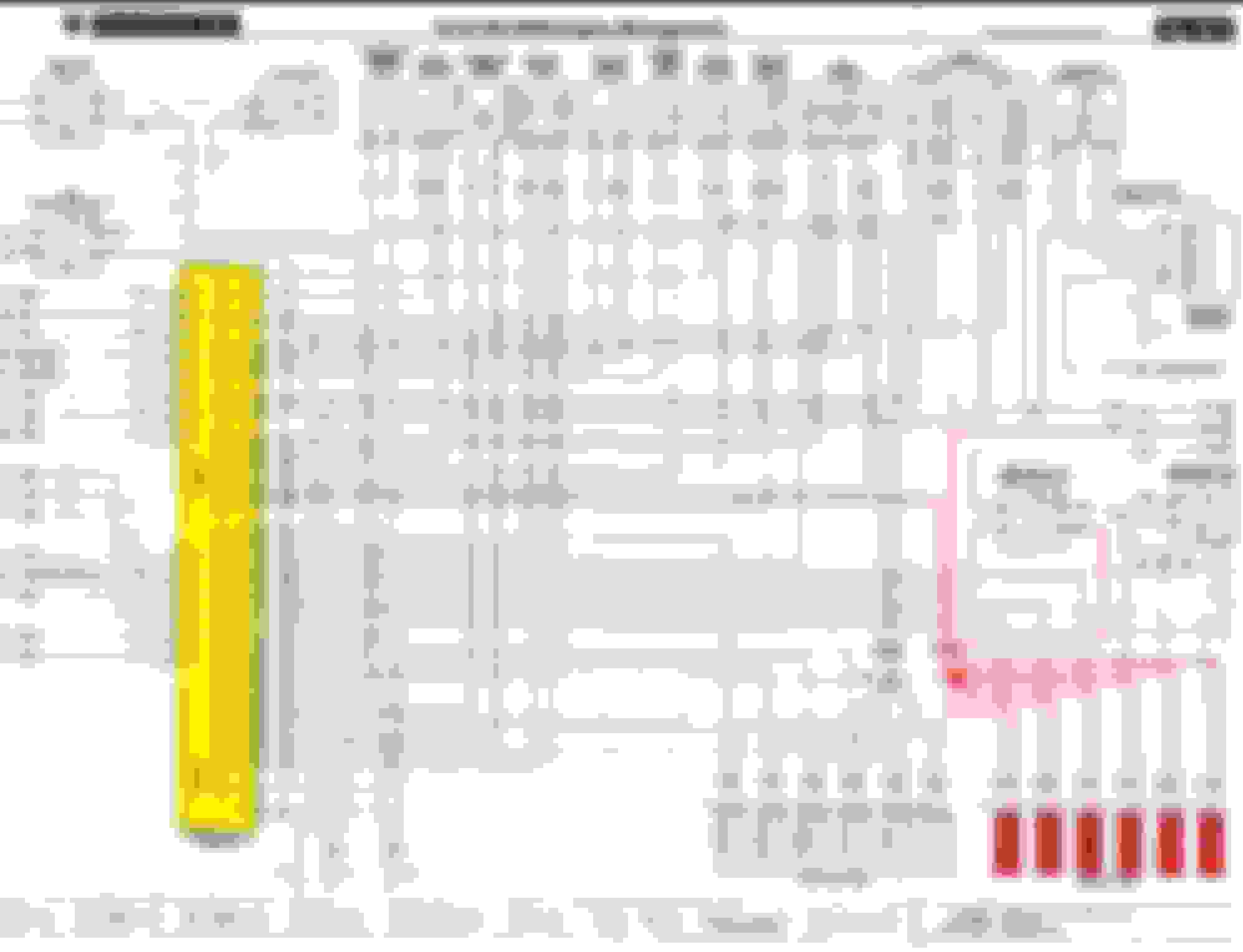
The 5.0 volts powering the CKPS is incorrect as it is the wire next to it # Red 22 in the wiring guide
A inductance sensor will generate it's own AC signal .
By design when you turn the key to the on position before the start position the fuel pump relay will click on then off for 3 - 5 seconds then will click on a 3rd time by the CKPS through the ECU . You may have observed that initial priming of the fuel rail as you bleed it off . This initial prime should give you a couple of seconds of engine light off before it relies on that 3rd relay click back on .
The initial click on click off comes though the ECU on the same control wire the 3rd click comes from . This tells you the ECU is alive and maybe not getting the CKPS signal for that 3rd click of the relay . This assuming you have good enough fuel pressure with the initial prime .
We're going to ignore the Camshaft sensor for now as the engine will start without it but takes more engine rotations to light off because it has reverted by design to the CKPS .
There is no wire splices between the ECU and the CKPS but if the sheilding on the wire is missing the ground you may have seen stray EMF feild picked up by the wire meter test .
At this point before spending too much time on meter testing would be to replace the CKPS if you can get assurance that you can get a refund if not needed depending on your relationship with the parts store .
Keep asking questions .
Last edited by Lady Penelope; Jun 16, 2018 at 10:45 AM.
To recap then ....the fact that initial prime of the fuel pump takes place tells us that the ECU is waking up ... YES??? Can we confirm this ?
If this is true and the EasyStart is failing even to produce a cough, the n everything is pointing to the ECU not switching on the coils? ... or the coils ( both of them ..unlikely? ) having failed ..
To me this is pointing more towards the fact that there is no command from what we now know to be a live ECU to tell the ignition system to fire the plugs?
I din't have time to pull the kick panel off and check the ECU connectors and the inertia trip ( Which is now coming back in as a contender ? How likely is it that these things trip randomly?) but presumably the fact that we have fuel initial prime suggests that the ECU connector is OK ...or maybe not ..some pins are making good contact, some are not ? I dunno why but I don't hold much hope for the ECU connector route...but I will look next time.
Why was there 2.25V on the CKPS if it's a dumb sensor? you think inducted current? hmm ...not sure? but surely if there IS a static DC on the CKPS that in itself would be enough to totally confuse the ECU? I assume the CKPS nominal output would be not much more than 2-3V anyway? .... Is this a clue ...this stray 2.25V .....could it be coming from the ECU as a result of a failure of the ECU? ....
BTW ..the fuel that came out of the line on cranking with the line broken at the rail was a pretty nasty colour///maybe quite old ,but again I would expect that to cause a complete stop / non start? ..unless ..is there a water detector in the system switching off if it detects water in fuel ?
somebody elsewhere just asked if it was an immobiliser issue?????
Last edited by trampintransit; Jun 17, 2018 at 06:34 AM.
To recap then ....the fact that initial prime of the fuel pump takes place tells us that the ECU is waking up ... YES??? Can we confirm this ?
You have verified the Black 19 on the ECU is providing the command ground in that specific section of the ECU is alive at that specific point in time of the starting sequence .
There is a " second power " to the ECU provided by the ECU controlled large relay behind the right headlight you can swap with the headlight relay in case it is intermittent , Mine had messed up wiring ( Brown / Purple ECU command ground wire ) under the ECU controlled relay socket from the PO .
The 6 wires getting their timed command ground to fire by the ECU get their control at first from the Camshaft sensor and then reverts to by design to the Crankshaft sensor . The single wire that powers all 6 coils pass through the Papa Indy ! connector position X
Editing
Jumping to the end :
somebody elsewhere just asked if it was an immobilizer issue ?
That would be pin Red 35 on the ECU and the 48 pin BT4 connector above the fuel tank can migrate loose , don't try too hard to engage the locking pins as the car's sheet metal hole can keep the connector halves faces from coming together .
Have you accurately verified with a external meter that the whole car voltage does not drop below the 11.4 volt point during starter rotation phase ? you did mention you saw 12 or about reading on the instrument cluster .
Have you verified the fundamental reading through the CKPS of 1300 ohms .
A ECU connector inspection is prudent , One possible explanation of your seeing power on one of the 2 Crankshaft sensor wires is that of corrosion or current path from a nearby pin on the ECU . There is a manufacturing flaw on the X300 where water migrates into the ECU connectors that is commonly seen by others . Better to completely remove the ECU for better visual inspection intead of jammed up with little space . The pins and sockets can easily be replaced with cheaply available parts .
More info
344111-1 TE Connectivity / AMP for the socket side of the connector :
The inertia switch can be unreliable and can be taken out of picture by jumping the 2 white wires on the switch connector .
Have you verified by sound other then the relay clicking that the pump is spinning ?
Have you replaced the fuel filter as a foundation maintenance item like the correct plugs as the AJ16 is a common cheap Champion copper and no exotics per Jaguar TSB .
Have you tried starter fluid to compensate for suspected fuel quality and pressure ?
Last edited by Lady Penelope; Jun 17, 2018 at 11:19 AM.
quick question ...this is all new to me all this complicated wiring diagrams...my stuff is normally older / simpler.
The Engine management diagram you used is 'SC' ..assume that's supercharged. I'm assuming NAS is North America...and ROW is Rest of World ....so ..my UK AJ16 Sovereign will be NA ROW ..is that right?
Re 'Starter fluid' ... I assume that's what we call Easy Start .... volatile 'fuel' sprayed into inlet....yes ..tried that...not a cough ..that's why I suspected that the problem wasn't fuel.
Next visit to the lock up ..is certainly going to centre around the ECU / inertia switch .. I'll jump the latter and check the former. . I was going to check this yesterday but by the time I got round to looking I was far too dirty from mucking around with an Armstrong Siddeley petrol tank to risk taking all that filth into the lovely cream interior of the Jag.
I'll certainly let you know what happens tomorrow...BUt ..can i just confirm that my car is AJ16 NA ROW ?
Not yet changed fuel filter or plugs ..but as I say ..the car was going like a bloody missile when it cut out...so unlikely to be plugs? It would fire wouldn't it ..even with crap plugs ..and there's fuel as I say at the rail.
I'm so reluctant to just start randomly throwing money at it ...by by the time I'd bought a new battery , CKPS Plugs , filters etc ...I'll just get a slap from the missus and possibly still have a non running car .....I need to eliminate all the free possible causes first to start it ...then I can work out how to spend next months money!
Re...'pump spinning' ...have we not proved that by filling a bottle from the cracked joint at the injector rail ...cranking causes fuel to floe into bottle ( Fuel looks horrible by the way)
Last edited by trampintransit; Jun 17, 2018 at 12:06 PM.
Correct . They are very much the same wire colors and pins . You do not have a EGR , second fuel pump , ect . But you do have a immobilization digital signal input into the ECU not in the North American market .
Last edited by Lady Penelope; Jun 17, 2018 at 12:05 PM.
Surely , now I look at the wiring diagram..do I not need really to be looking at the output from ECU pin Red 33 ? is that supplying the trigger voltage to the coils ? Since we suspect that fuel delivery is probably ok ?
The colour codes are confusing me ....the wire to the coils are 'WK' there's no 'K' in the colour codes on page 15?
What about the AMS? I'm still trying to find time and brains to interpret the 170 page electrical guide.....can I test for the AMS working ..the only reason I bring that up is because I did check the air filter and in doing so noticed there is a mesh grill in front of the AMS in the inlet tract ...it was broken, although no parts of it seemed to be missing , it looked like break up was imminent .. I pulled the tube apart and removed the mesh entirely. .. could the shock of being pulled apart have damaged AMs ? I doubt it...'cos it subsequently started and ran ...and if I'm not mistaken a failed AMS won't cause a car to come to a dead stop will it? It'll default to known airflow maps?
Last edited by trampintransit; Jun 17, 2018 at 12:55 PM.
The Mass Air flow sensor can be totally disconnected and the engine will still run but not as good as it reverts to a default set of " maps " in the ECU .
The center wire on the MAF sensor will read 1.2 volts DC at the correct idle RPM and climb towards 5.0 on throttle up .
You can read the TPS center wire at idle of 0.60 volts at idle stop with the key on and engine not running .
ECU pin Red 33 ? I or someone will get back with you later gotto run a errand .
Right ..plenty to go on now ... to confirm ...to test voltage whilst cranking ...use engine earth and positive bolt on RH fuse box in engine bay?? Yes? ...btw ...according to the electrical guide, there is an earth next to that RH fuse box...but I don't see it...I'll look again tomorrow now I have a print out of earths.
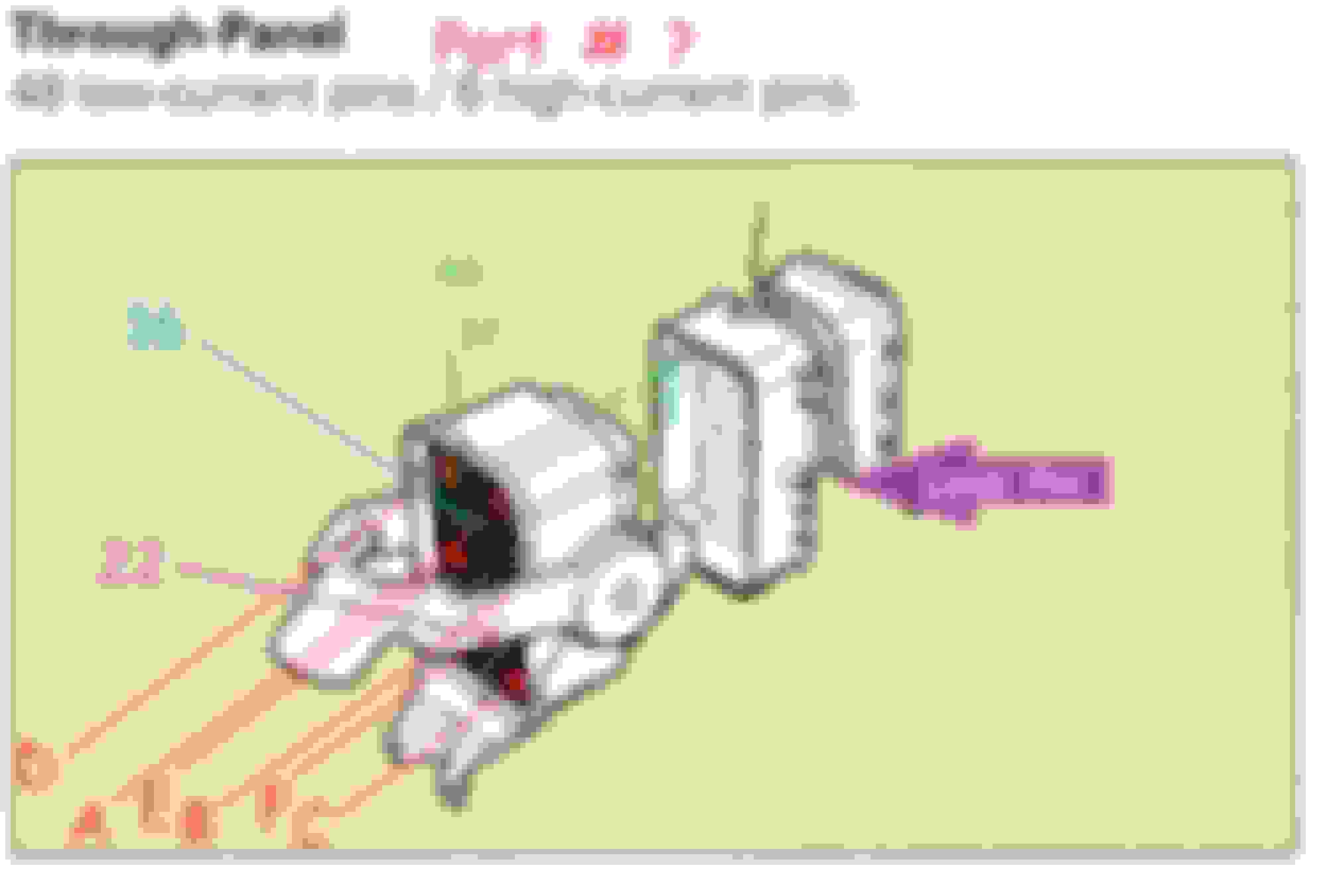
In an earlier post you posted a pic of the Papa Indy connector ..that didn't appear until later ..just seen it ...interestingly it looks a liitle different on my car ..different style connector....but I'll check stuff there ..but I need to learn how to read the guide to see what's what in terms of pins. The copy of a pic of a connector you posted under the pic of Papa Indy ..that's not Papa Indy itself is it ..? I don't think the connector in that position on my car has that many connectors! Is PI feeding the coils then , via WK wires?
I'm getting to grips slowly with interpreting the guide ...I get where the connectors are reffered to on page 53 ...and thus where they are on the car ..but struggling to find them on the diagram ... anyway ..onwards and upwards...
Now ,I'm sure I'm being thick here, but on the diagram fig 04.2 ... the ECU ,doesn't seem to have red 23 ..and red 26 is labelled 'torque control' ? ...ah ..hang on ..it's BLACK 23 /26 !
Last edited by trampintransit; Jun 17, 2018 at 03:16 PM.
The ground stud is on the lower beam of the engine bay or easier is the muti wire ground studs on the rear engine firewall .
The Papa Indy 1 and 61 connectors are next to each other . On the later 97 models they are both white or black .
Notice how the coil power source it tapped into the ECU as the " first power " before the ECU can provide a ground to the ECU controlled relay giving it " second power "
Coil power comes out of point 32 ll circled which goes through Papa Indy 1 position 4 as the WK wire . Point 32 ll circled gets it's power from fuse # 12 / 10 amp RH engine fuse box on page 37 . The fuse gets it's power from the king relay ( ignition positive relay ) which is closed by the ignition switch through pin 3 to pin 5 to provide a ground page 39 . Swap the relay first and feel for it to click as it may be intermittent .
You are correct on the Black 23 and 26 .
cramps ruining my concentration .
Last edited by Lady Penelope; Jun 17, 2018 at 07:44 PM.