I just finished installing an aftermarket Boss™️ radio into my XJ40. I wanted to make an all-in-one post for anyone looking to do the same. I noticed going through the forums there was a lot of scattered information and figured we could consolidate.
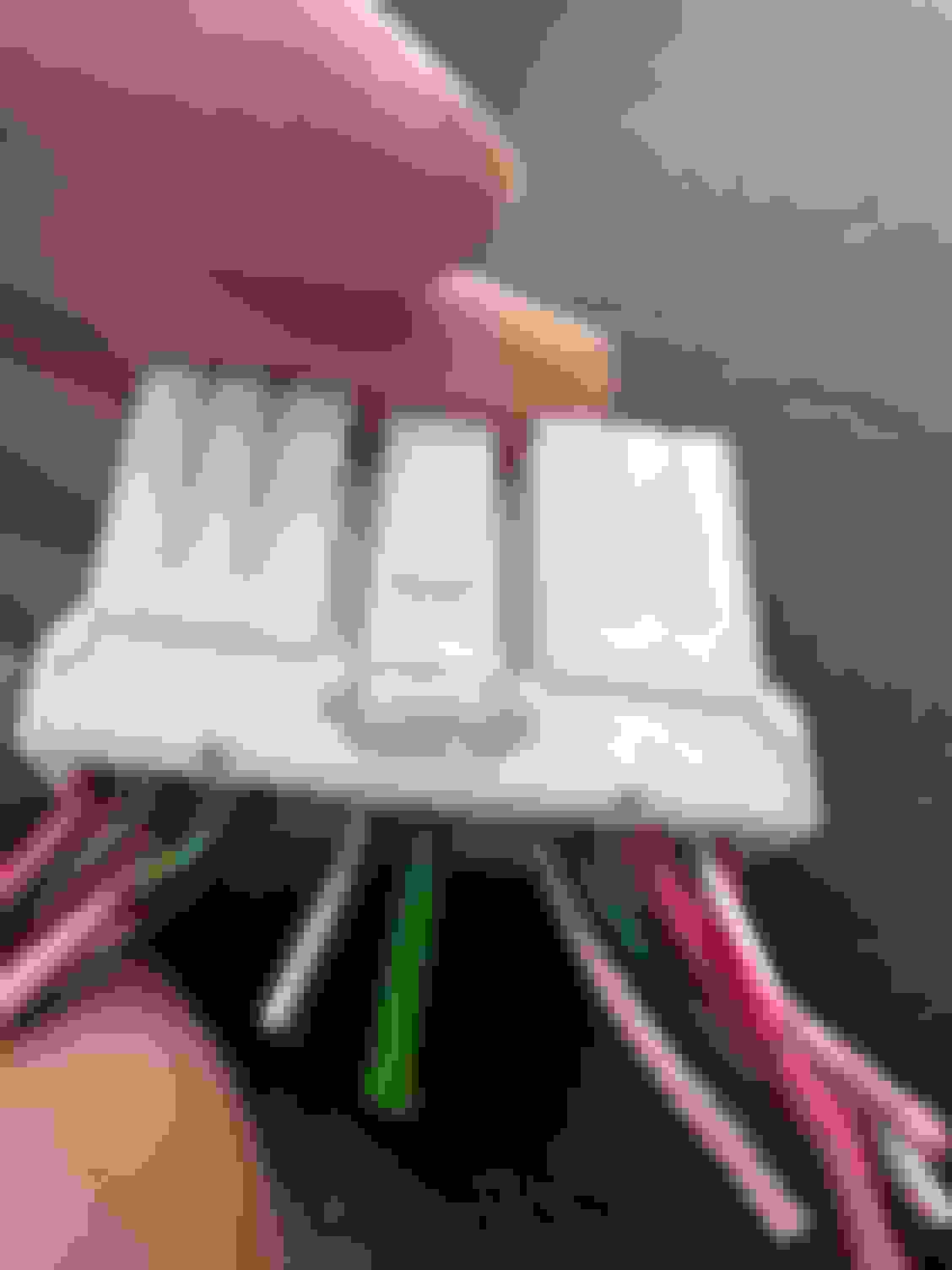
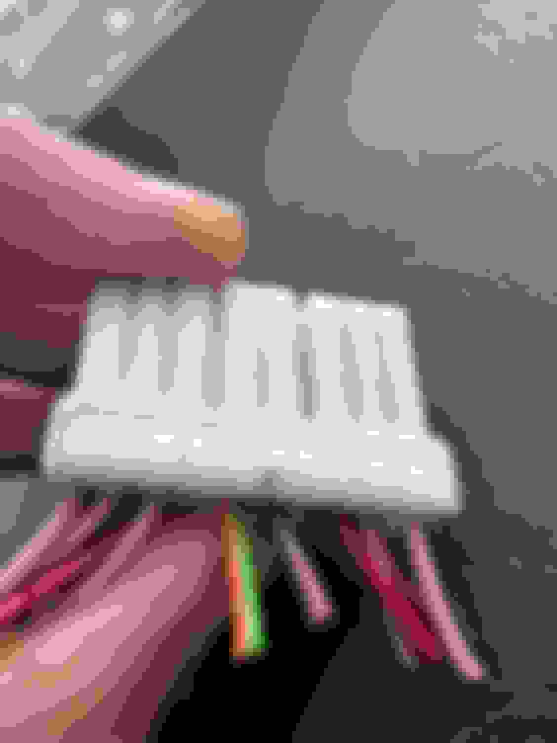
I also had a question about 4 remaining wires and what they might go to. I’ve attached photos to make our lives easier. These wires are Red/Pink, Red/Purple, Pink/Orange, Red/Lime Green. There was also another Red/Dark Green that I figured must be another (-) neg wire (one for left/one for right)
(Sidenote) the Jag sound system is pretty weak on songs with a lot of bass 😂 Will definitely need to swap those out if you want to have a pleasant listening experience.
Okay, so shoutout to user @Jagfix38. His post (which I’m leaving a photo of) was the most helpful resource when swapping the wires from the old harness.
Heres a simple video on how to remove the ashtray, trim, climate control/radio panel.
https://youtu.be/VqxXTtE30yg?feature=shared
I’ve attached the harness from my car with the wires detached and the pins to see what wire went where.
Here’s the list:
Large black cable bolted to unit = Ground
1 Red/White = Left Front Positive (+)
2 Red/Brown = Left Rear Positive (+)
3 Red/Darker Green = Left Front Negative (-)
4 Lime Green/Black = Not sure. Hooked up to antenna wire but my antenna didn’t work prior so not sure what it’s actually for
5 Red/ Lime Green = Don’t know
6 Red/Purple = Don’t know
7 Pink/White = Right Front Positive (+)
8 Pink/Yellow = Right Rear Positive (+)
9 Pink/ Lime Green = Right Front/Rear Negative (-) (pretty sure mine was split into 2 pink and lime green coming from 1 wire)