
Electric series 1 XJ6 project

Senior Member


Joined: Feb 2017
Posts: 412
Likes: 176
From: San Diego, CA
Carl I believe you are correct about the vacuum canister in the car not being big enough to provide vacuum for the brake booster. I think he is going to need a larger canister with larger hoses. The hoses on my canister are quite small compared to the hose going to the brake booster.
And yeah Roger is right, with no trans in the car, a gps speedo is the way to go here.
And yeah Roger is right, with no trans in the car, a gps speedo is the way to go here.


Thread Starter
|
Member
Joined: Dec 2015
Posts: 79
Likes: 76
From: San Jose, CA
thanks for the tips regarding the vacuum system guys, I'll see how it turns out and add another reservoir if the pump can't keep up with my foot.
Ron, that's a sweet mustang - I'm going for a little more useable trunk space though I'm using a power steering pump from an Opel Astra, it seems to be a popular one for conversions
Carl, most batteries up in the trunk, but I'm not going to let that 24 gallons worth of fuel tank space to go waste either... planning to keep the spare tire as well
I did make a little bit of progress today mounting the motor to the subframe. I've decided to try mounting the motor directly to the subframe. As the subframe bushings are rubber isolated, I'm hoping that this will be sufficient to mechanically isolate the two.
I've also decided on a method to mount the power steering pump and vacuum pump adjacent to the motor. This should take advantage of the motor's mechanical isolation via the subframe bushings and also by each pump's own bushings. I'm not the most seasoned hand at fabricating so this part is a little slow going unfortunately
Ron, that's a sweet mustang - I'm going for a little more useable trunk space though
I'm using a power steering pump from an Opel Astra, it seems to be a popular one for conversionsCarl, most batteries up in the trunk, but I'm not going to let that 24 gallons worth of fuel tank space to go waste either... planning to keep the spare tire as well
I did make a little bit of progress today mounting the motor to the subframe. I've decided to try mounting the motor directly to the subframe. As the subframe bushings are rubber isolated, I'm hoping that this will be sufficient to mechanically isolate the two.
I've also decided on a method to mount the power steering pump and vacuum pump adjacent to the motor. This should take advantage of the motor's mechanical isolation via the subframe bushings and also by each pump's own bushings. I'm not the most seasoned hand at fabricating so this part is a little slow going unfortunately

Veteran Member
Joined: Jul 2012
Posts: 6,796
Likes: 2,403
From: Walnut Creek, California
1. Cut, weld and grind. It can be frustrating, yet satisfying. In my past repetoire, an HF sourced power metal cutting band saw. An oxy acetylene torch set. A hand held grinder, also HF sourced. I've turned out some fairly decent parts.
2. You might have a look at the two piece drive shaft. It's alignment s critical. And, as your changes are considerable....
Carl
2. You might have a look at the two piece drive shaft. It's alignment s critical. And, as your changes are considerable....
Carl
Thread Starter
|
Member
Joined: Dec 2015
Posts: 79
Likes: 76
From: San Jose, CA
Motor is suspended on mounts! Progress continues..
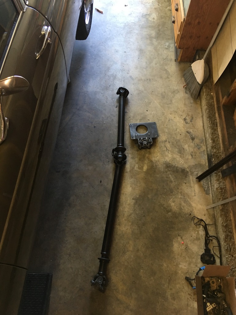
The driveshaft is exactly 6.5" too short, so I'll be taking it in to my local shop for a lengthen and rebalance treatment. It should look much like an OEM driveshaft when it's done
The driveshaft is exactly 6.5" too short, so I'll be taking it in to my local shop for a lengthen and rebalance treatment. It should look much like an OEM driveshaft when it's done

Thread Starter
|
Member
Joined: Dec 2015
Posts: 79
Likes: 76
From: San Jose, CA
Thanks!
Batteries are going up front. Looks like I mis typed in haste up above, since the cells package in a nice brick shape, just like the engine bay, this should work out very nicely indeed. With the initial 24kW pack the front end will be pretty close to the weight of the six. The second pack ~90kW will even the weight out to be almost exactly the same as a fully fueled XJ12, so stock springs can keep the original ride quality and height
Batteries are going up front. Looks like I mis typed in haste up above, since the cells package in a nice brick shape, just like the engine bay, this should work out very nicely indeed. With the initial 24kW pack the front end will be pretty close to the weight of the six. The second pack ~90kW will even the weight out to be almost exactly the same as a fully fueled XJ12, so stock springs can keep the original ride quality and height
Last edited by Bry5on; Jul 14, 2017 at 09:33 AM.


Veteran Member
Joined: Jul 2012
Posts: 6,796
Likes: 2,403
From: Walnut Creek, California
Aha, your fab skills are under stated ! Looking great.
However:
1. I hope your drivel line is now a one piece line sans the 'touchy" center U joint.
2. The front motor mount perplexed me a bit. I am not a mechanical engineer, or even close. But, triangulation came in to my lexicon early on. No evidence of it in the front mount. In view of the instant and high
torque inherent in motors as opposed to IC engines, it does need attention. Perhaps, a simple bar???
Carl
Thread Starter
|
Member
Joined: Dec 2015
Posts: 79
Likes: 76
From: San Jose, CA
Aha, your fab skills are under stated ! Looking great.
However:
1. I hope your drivel line is now a one piece line sans the 'touchy" center U joint.
2. The front motor mount perplexed me a bit. I am not a mechanical engineer, or even close. But, triangulation came in to my lexicon early on. No evidence of it in the front mount. In view of the instant and high
torque inherent in motors as opposed to IC engines, it does need attention. Perhaps, a simple bar???
Carl
However:
1. I hope your drivel line is now a one piece line sans the 'touchy" center U joint.
2. The front motor mount perplexed me a bit. I am not a mechanical engineer, or even close. But, triangulation came in to my lexicon early on. No evidence of it in the front mount. In view of the instant and high
torque inherent in motors as opposed to IC engines, it does need attention. Perhaps, a simple bar???
Carl
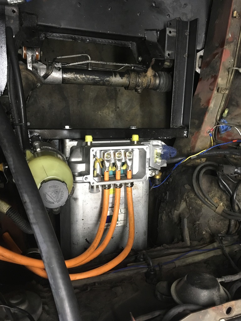
Regarding the front motor mount - you picked up on a very good point
in order to be able to install the mount, I couldn't add a welded box section on the bottom. The lower extension will get a bolt in strengthening member (with under tray!) that ties into the lower side of the subframe via some blind rivnutsAnd as promised, the mount installed with vacuum and power steering pumps
Last edited by Bry5on; Jul 16, 2017 at 11:39 AM.
Thread Starter
|
Member
Joined: Dec 2015
Posts: 79
Likes: 76
From: San Jose, CA
Bonus evening update! This afternoon I was able to wire up the DC/DC 12v charge system and get the throttle pot hooked up to the original pedal. I am now running the car off of an outlet in the garage as my DC/DC also takes AC input

Got my doubts as to that mount handling an instant 4-600ftlbs of torque.
But this is a cool project, love it. Very heavy car for electric, but gorgeous!
Brakes... already have electric for the power steering, can't you plumb it to a hydroboost? Cheap used and simple to install.
Subbed...
But this is a cool project, love it. Very heavy car for electric, but gorgeous!
Brakes... already have electric for the power steering, can't you plumb it to a hydroboost? Cheap used and simple to install.
Subbed...
Thread Starter
|
Member
Joined: Dec 2015
Posts: 79
Likes: 76
From: San Jose, CA
we'll see how the bracket holds up. Hopefully once it's fully tied in, and along with the rear mount, it should be plenty to withstand the torque.
Hydroboost could be doable, but the conversion is one less thing for me to worry about!
Today was a pretty light day - I started fabricating the under tray/lower support for the motor mount and I also wired up the fuel gauge
I did run into a snafu while I had the center console out to run the reverse trigger wire and remove the shift cable. I probed the reverse light switch to ensure it was getting a proper 12v signal and it was repeatably operational, as this switch is going to be what puts the car into reverse. I then soldered in and heat shrinked a splice off of the switched side to run into the motor inverter. After doing this and hooking everything up, I no longer have a 12v signal into the switch! O_o I looked through the fuse box, checked my wiring for shorts, but found neither a fuse nor a hard short.
Question: which fuse controls this wire and where is it located? It's the same hot wire that also goes to the PRND illumination light
Veteran Member

Joined: Nov 2011
Posts: 1,262
Likes: 326
From: Atherton Tablelands Nth Qld Australia
Have you considered solar cells on the roof, & a regenerative braking system? You're never going to generate enough to run off those entirely. But they could help extend the range.
Thread Starter
|
Member
Joined: Dec 2015
Posts: 79
Likes: 76
From: San Jose, CA
Great ideas, both!
I hadn't considered a solar roof but you bet this thing has regenerative braking. The amount of regen is currently software selectable, in addition to there being an input on the inverter board for a brake pressure sensor. Presumably this can be set to provide regen proportional to disc brake effort, maybe even enough to remove the rear brake system entirely...
I wonder if anyone makes a sort of 'roll up' solar panel that I could stash in the trunk..
Veteran Member
Joined: Jul 2012
Posts: 6,796
Likes: 2,403
From: Walnut Creek, California
Backup light switch? I don't think you have one anymore. In my series 3, using later version of the BW transmission in your car, it was switch on the transmission. Left side as I recall. Multi purpose, Neutral start and back up lights.
Carl
Carl

Senior Member
Joined: Oct 2016
Posts: 184
Likes: 49
From: Brisbane
Roll up Solar Panels are a thing, available online or in Camping stores.
The idea of solar panels is poo-pood on the DIY electric car forum as not justifiable given the weight, wind resistence, complexity and 'minimal' output. possibly just to help charge the 12v battery but not really for range extension. I think a good system can output reasonable wattage and a roll up/ ultra thin panel could remove the wind resistance factor.
Its something i had considered for my project, either the roll up kind or i was thinking about making the trunk/ boot lid, front bonnet and guards out of fibreglass and inlaying individual solar cells to maximuse the use of space. Its currently at the bottom of the list under 'cool but time consuming/ impractical' ideas.
Veteran Member
Joined: Nov 2011
Posts: 1,262
Likes: 326
From: Atherton Tablelands Nth Qld Australia
There has been a major breakthrough in fflexible solar cells recently, with them now able to be printed onto plastic, which reduces weight, drag, & costs.
http://www.momentumenergy.com.au/habitat/renewable-energy/solar-cells-printable/
http://www.momentumenergy.com.au/habitat/renewable-energy/solar-cells-printable/
Thread Starter
|
Member
Joined: Dec 2015
Posts: 79
Likes: 76
From: San Jose, CA
Progress! Lengthened driveshaft is in and fits like a glove. I've also got the inverter complete and started wiring it up to the car for testing without a high voltage DC bus. Here's a video showing the start sequence and what happens on the dash during that time:
and some photos to accompany the video
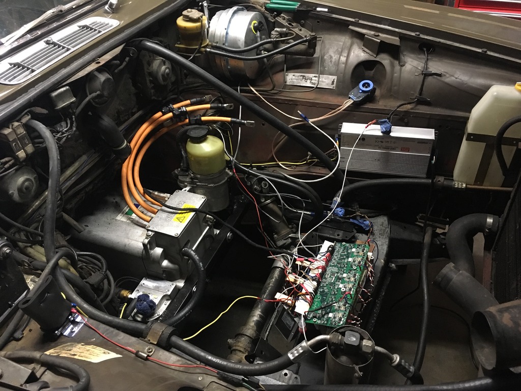
and some photos to accompany the video


