
Wiring to Coil Series III


Thread Starter
|
Member
Joined: Feb 2022
Posts: 59
Likes: 14
From: NYC
Hello all,
I've been trying to sort out the intermittent no start on my Series III, and I think I've figured out the problem. I've got no spark coming out of the coil, and I think I know why. I'm only reading ~7.5V across the coil poles, even when reading directly across the leads unplugged from the coil. I'm also reading ~0.1V across the amplifier leads when disconnected from the coil. The coil itself reads fine, with ~1 Ohm across the poles and 9.5K Ohms from the positive to secondary winding. I tried this with two different batteries, one of which was freshly charged. The voltage across the battery leads with the first, lower, battery was ~11.5V, and I expect the fresh battery would have produced closer to 12V.
I've been reading the wiring diagrams, and I can't figure out where the coil is getting its current from. The diagram confusingly shows three leads coming into and out of the amplifier, when there are only two on mine. Further, the wiring diagram shows three leads coming off the ballast resistor, when mine had only two (I replaced the old coil and resistor a year ago with an internally resisted coil). Further still, the diagram shows only one lead coming off the positive of the coil, when mine has two. This diagram actually contradicts another diagram in the same part of the manual, which shows the two lead-per-pole setup my coil has. As such, I'm no closer to understanding where to start looking to find the cause of this low voltage.
As always, looking for advice on the matter.

Senior Member


Joined: Dec 2011
Posts: 778
Likes: 459
From: Central California

Two wire Ignition amplifier
Intermittent ignition can come from: 1. Distributor pickup 2. GM module in the amplifier 3. Ignition Coil 4. Ignition switch , or the wires in between each unit.
Jaguar XJ6 S3:
1. C to (-) terminal of Ignition Coil = White with black stiped wire
2. B to (+) terminal of Ignition Coil = White wire
3. IGN SW to (+) terminal of Coil = Brown (or White) wire
4. EFI to (-) terminal of Ignition Coil = White with Black wire
5. Tach to (-) terminal of Ignition Coil = Slate with Blue spiral stripe wire
GM module will be intermittent when hot, before a complete fail. In the Lucas Ignition amplifier there is a "Radio Interference Capacitor" and a Current Fault Diode, neither is required for ignition and both can short to ground causing ignition failure. When you have a no start situation, unhook both inside the Amplifier for T/S.
Ignition switch is age related. Forum members have disassembled, cleaned and lubed electrical portion of Ignition switch. You can buy electrical portion only, from usual sources.
Distributor and Ignition amplifier need good grounds. The ground (in picture) on the ignition Amplifier mounting bolt, doesn't have to go to Battery ground post, any good grounding point on engine is ok.
It is a process of elimination to find where the fault is.
Rgds
David
Last edited by David84XJ6; Apr 11, 2024 at 04:41 PM.

Senior Member
Joined: Jun 2022
Posts: 118
Likes: 24
From: San Francisco, CA
I had a no start situation that I linked to a faulty coil. When I replaced the coil, I had a brief scare when the new coil didn't give me a spark, but was remedied when I played with the wires on the negative end of the coil. My question is what exactly the "EFI" wire is? Is that going to the ECU ? From process of elimination, I'm figuring that has to be the problem - a old and corroded wire or connection. My second question is whether a old EFI wire/bad connection can burn out a coil since the coil was pretty new. Any thoughts on this ? To make matters more complicated, I replaced the amplifier (it remains on the car because of the screw holes) with a MSD 6 unit and corresponding coil. It did improve idling substantially and I do like the system.

Senior Member
Joined: Dec 2011
Posts: 778
Likes: 459
From: Central California
I had a brief scare when the new coil didn't give me a spark, but was remedied when I played with the wires on the negative end of the coil. My question is what exactly the "EFI" wire is? Is that going to the ECU ? From process of elimination, I'm figuring that has to be the problem - a old and corroded wire or connection. My second question is whether a old EFI wire/bad connection can burn out a coil since the coil was pretty new. Any thoughts on this ? To make matters more complicated, I replaced the amplifier (it remains on the car because of the screw holes) with a MSD 6 unit and corresponding coil. It did improve idling substantially and I do like the system.
The corroded wire to to ecu would prevent injectors getting a fuel pulse, but IMO should not cause a coil failure. With the MSD box, are you getting Tach signal ok? They have a separate module that is added to get "Tach and Fuel injection signal" correct. Tach/Fuel Adapter, Points and Amplifier
(Factory Ignition Module)If you are triggering an MSD Blaster, 5,6, or 7 Series Ignition with its white wire or points terminal, you will need this Tach Adapter. This unit will correct the operation of most voltage triggered tachometers or fuel injection systems that do not work directly off the tach output terminal of the MSD Ignition Unit.
 Magnetic PickupIf you are using the magnetic pickup input (green and violet wires) to trigger your MSD Ignition, you will need the #121-8920 Tach Adapter. This will correct the operation of most voltage triggered tachometers that do not work directly off the tach output terminal of the MSD Control. This Adapter should also be used on current triggered tachs (hooked in series with the ignition switch).
The corroded wire to to ecu would prevent injectors getting a fuel pulse, but IMO should not cause a coil failure. With the MSD box, are you getting Tach signal ok? They have a separate module that is added to get "Tach and Fuel injection signal" correct.
MSD Tach Adapter - Points or Amplifier and Magnetic Pickup
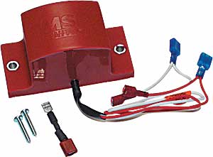 Tach/Fuel Adapter, Points and Amplifier
(Factory Ignition Module)If you are triggering an MSD Blaster, 5,6, or 7 Series Ignition with its white wire or points terminal, you will need this Tach Adapter. This unit will correct the operation of most voltage triggered tachometers or fuel injection systems that do not work directly off the tach output terminal of the MSD Ignition Unit.
 Magnetic PickupIf you are using the magnetic pickup input (green and violet wires) to trigger your MSD Ignition, you will need the #121-8920 Tach Adapter. This will correct the operation of most voltage triggered tachometers that do not work directly off the tach output terminal of the MSD Control. This Adapter should also be used on current triggered tachs (hooked in series with the ignition switch).
Senior Member
Joined: Jun 2022
Posts: 118
Likes: 24
From: San Francisco, CA
The guy who installed the MSD for me told me he didn't need it. That really surprised me. The tach works as advertised. It's possible he had someone else in the garage do the install and the Tach adapter is hidden under the air filter housing where I can't see. I'll take a more detailed look this weekend. Is it possible it would work without the adapter? If not - do I have a MSD unit in my car that isn't hooked up? Hmmmm

Thread
Thread Starter
Forum
Replies
Last Post
Currently Active Users Viewing This Thread: 1 (0 members and 1 guests)