
Delanair Mk111 Repair

Thread Starter
|
Veteran Member
Joined: May 2010
Posts: 4,638
Likes: 2,583
From: Vic Australia
First off I needed to replace the leaking heater core and replace the connectors that had been damaged by coolant.
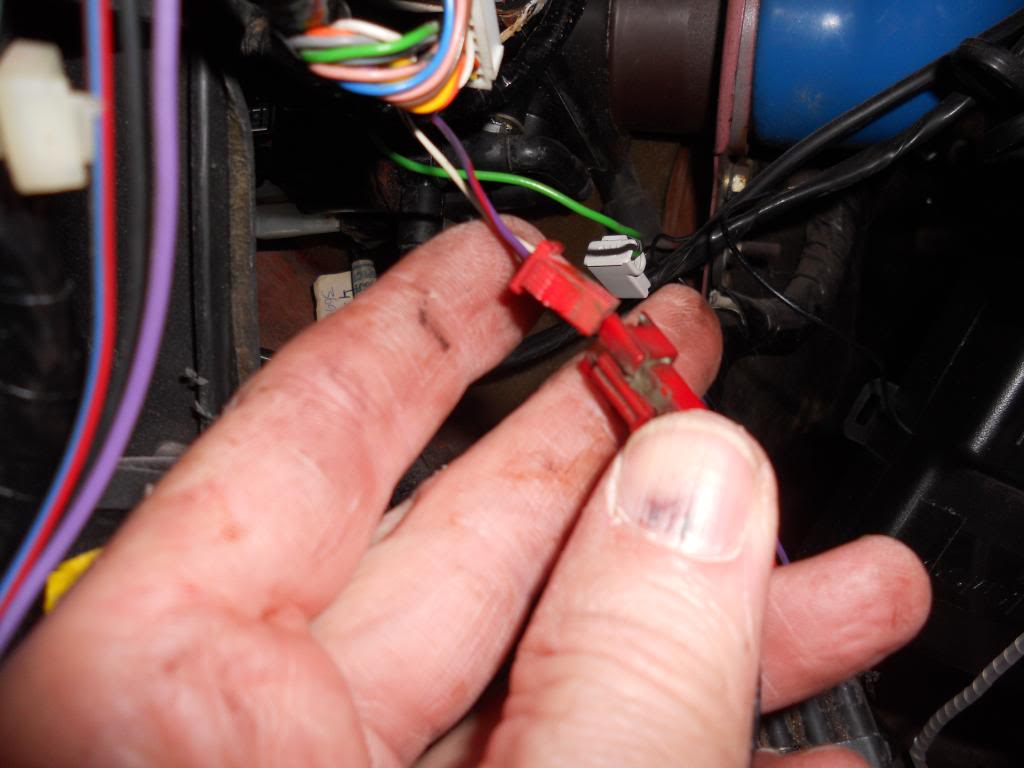 New Main cabin power connector got this from Jaycar

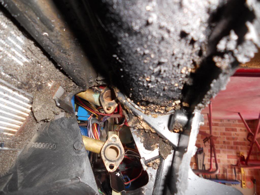
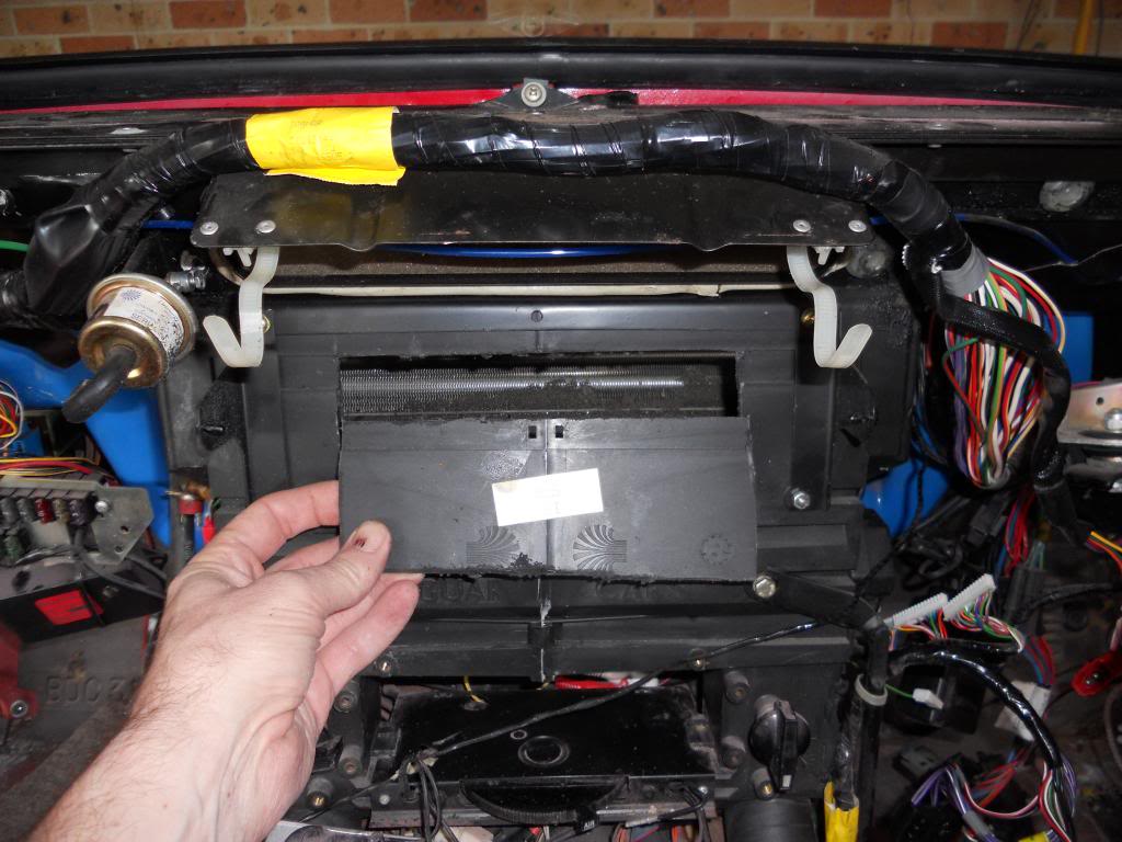
All of the junk in the AC box, This needed cleaning.
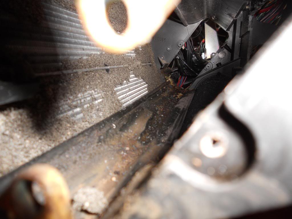
This pic is upside down but it gives an idea how bad it was in there.
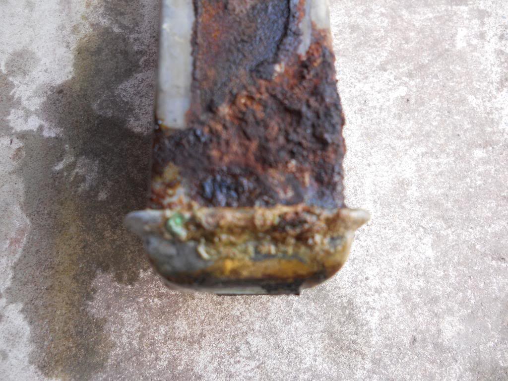
Dead Heater core, definitely been leaking.
So I cut the front off the AC box to gain access to clean it. I forgot to take a photo but I sealed the front of the box up with a plate of 1mm aluminum, riveted and silicone.
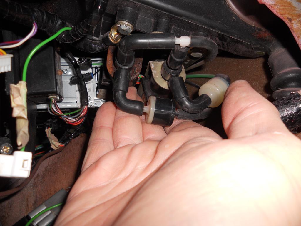
The solenoid on the Left controls the center vent.
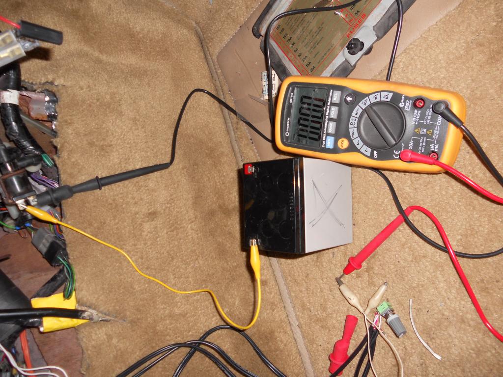
Checking the current draw on the solenoid before re-installing the AC controller. Don't want to blow it up again. About 400-500mA is good.
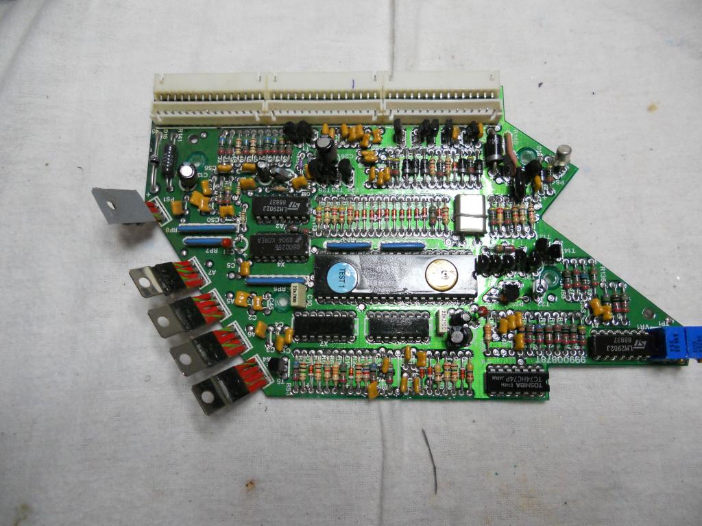
AC Controller on the bench.
I had my AC re-gassed last week and not everything was well. I had cold air coming from the defrost vents, Hot air from the footwell vents and no center vent operation at all. My car is an 1989 with the Delanair Mk111 system, this system was used from about 1987 until about 1992.
A big thanks to Doug for the Manual, which made diagnosis easier and quicker.
Anyway I am going to try and simplify diagnosing problems with this system. As it turns out I had 3 different issues, that took me the best part of the day to find and rectify. At least 2 were caused by having the dash out of the car and replacing the heater core
Hot air in the footwell was caused by the lower blend flap being re-installed incorrectly. A PITA to fix with the dash back in the car.
The main issue was no air from the center vents. To cut a long story short I used the manual to find the problem which turned out be a failure in the AC control unit. At some point the driver transistor that turns the center vent solenoid on had failed. These PCB's are a real PITA to fault find as the PCB is multi-layered with all the tracks running on the inner layers.
To make it easier for others I have put together a simple getting started flow chart before diving into the measurements in the manual.
I hope this helps. SEE PDF AT BOTTOM OF POST


All of the junk in the AC box, This needed cleaning.

This pic is upside down but it gives an idea how bad it was in there.

Dead Heater core, definitely been leaking.

So I cut the front off the AC box to gain access to clean it. I forgot to take a photo but I sealed the front of the box up with a plate of 1mm aluminum, riveted and silicone.

The solenoid on the Left controls the center vent.

Checking the current draw on the solenoid before re-installing the AC controller. Don't want to blow it up again. About 400-500mA is good.

AC Controller on the bench.

I had my AC re-gassed last week and not everything was well. I had cold air coming from the defrost vents, Hot air from the footwell vents and no center vent operation at all. My car is an 1989 with the Delanair Mk111 system, this system was used from about 1987 until about 1992.
A big thanks to Doug for the Manual, which made diagnosis easier and quicker.
Anyway I am going to try and simplify diagnosing problems with this system. As it turns out I had 3 different issues, that took me the best part of the day to find and rectify. At least 2 were caused by having the dash out of the car and replacing the heater core
Hot air in the footwell was caused by the lower blend flap being re-installed incorrectly. A PITA to fix with the dash back in the car.
The main issue was no air from the center vents. To cut a long story short I used the manual to find the problem which turned out be a failure in the AC control unit. At some point the driver transistor that turns the center vent solenoid on had failed. These PCB's are a real PITA to fault find as the PCB is multi-layered with all the tracks running on the inner layers.
To make it easier for others I have put together a simple getting started flow chart before diving into the measurements in the manual.
I hope this helps. SEE PDF AT BOTTOM OF POST
Last edited by warrjon; Nov 26, 2013 at 01:09 PM.

Veteran Member


Joined: Mar 2008
Posts: 25,541
Likes: 11,739
From: Pacific Northwest USA
Good work 
This is something I've often wondered about.
What system was used in the later cars?
I *thought* the Delanair Mk III was used until the end....perhaps with some revisions.... but that manufacturing had been turned over to (or bought by) Valeo.
Cheers
DD
My car is an 1989 with the Delanair Mk111 system, this system was used from about 1987 until about 1992.
This is something I've often wondered about.
What system was used in the later cars?
I *thought* the Delanair Mk III was used until the end....perhaps with some revisions.... but that manufacturing had been turned over to (or bought by) Valeo.
Cheers
DD
Thread Starter
|
Veteran Member
Joined: May 2010
Posts: 4,638
Likes: 2,583
From: Vic Australia
Thanks Doug. Hopefully the PDF flowchart I attached to my last post will help the next poor sod who has to diagnose these systems.
I heard something about the Mk4 - who knows what Jaguar did, most of this information is in someones head.
I heard something about the Mk4 - who knows what Jaguar did, most of this information is in someones head.
Thread Starter
|
Veteran Member
Joined: May 2010
Posts: 4,638
Likes: 2,583
From: Vic Australia
A warning. Before I put everything together I measured the current draw from both vacuum solenoids, both measured under 500mA (0.5A). Then yesterday the horrible electronic component I am dying smell and the center vents closed.
The center vent solenoid decided after working for a couple of days to draw just over 1A. The AC controller did't like it and died again. This time I have added a 630mA inline fuse in the supply to both solenoids to protect the controller. I will be dong this to the other 2 vacuum solenoids (heater and recirculation).
I would strongly recommend everybody add these fuses to protect the AC controller. Solenoids can and do fail, they usually draw additional current and POP no more controller.
They are easy to install. Use an inline fuse holder and crimp INSULATED spade terminals to each end (male one end and female the other) and just plug it into the + side.
Last edited by warrjon; Dec 6, 2013 at 09:46 PM.

Thread
Thread Starter
Forum
Replies
Last Post
Currently Active Users Viewing This Thread: 1 (0 members and 1 guests)