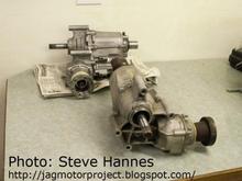
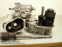
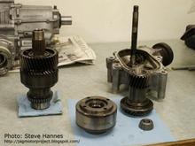
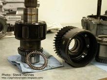
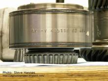
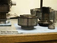
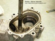
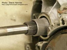
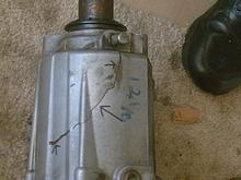
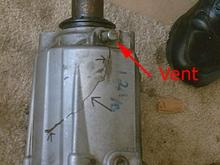
Steve Hannes: Also, and to dispel some rumors, there is no way this transfer case can function without the VC and with the existing gearset design. Here is another picture of the mainshaft. You can see the inner and outter shafts clearly here. The outer spline is "fed" by the transmission; the inner splined shaft is the output to the front wheels and reduced in RPM by the planetary gearset. Both shafts in this case have tapered roller bearings on both ends. Tapered roller bearings must be loaded properly or they will quickly wear out. If too much pressure (load) is applied, the bearing will, in a sense, crush itself, quickly run very hot and scorch the rollers and races. On the other hand, if not enough load is applied, then the bearing will run loose, rattle and eventually destroy itself that way. Too loose and the shafts will chatter causing the mating gearsets to mesh incorrectly, eventually destroying the gearsets. But, the bearings will go way before these gearsets are destroyed.
***** more info: http://jagmotorproject.blogspot.com/2007/02/motor-project-17-transfer-time.html *****