When you click on links to various merchants on this site and make a purchase, this can result in this site earning a commission. Affiliate programs and affiliations include, but are not limited to, the eBay Partner Network.
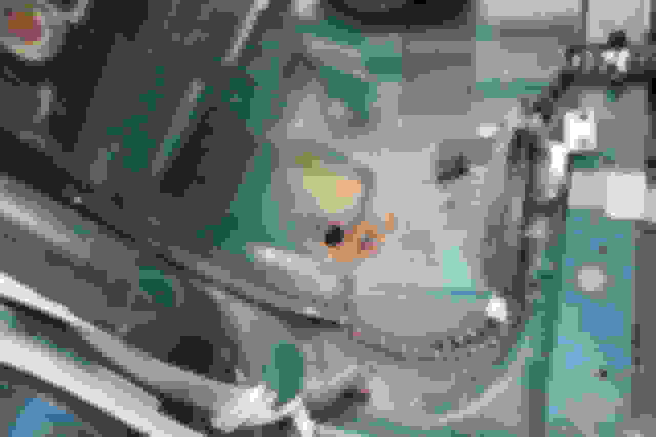
The photo below shows the mounting stud where the positive lead from the starter/alternator passes through the firewall on its way through the cabin to the lug under the rear seat, then to the battery.
I haven't looked yet, so my apologies if this is an obvious question; but where is the other end of this firewall stud? Is it accessible from up under the car on the exterior, or does the stud pass through into the interior right hand foot-well?
Last edited by al_roethlisberger; 02-10-2018 at 10:13 PM.
If it's mounted to the frame it would be a negative grounding stud , Will look at mine in the morning . The 3 insulated positive power through studs are on the upper edge of the firewall and the starter / alternator stud is the one off center . Remove the wire and verify the stud is tight as the cabin side wire is on the other side . From the cabin it is way up high as you climb under the dash
Last edited by Lady Penelope; 02-10-2018 at 10:38 PM.
5) ST8, fuses on battery positive terminal, or one other stud in the trunk?
So, in the attached photo, "ST6" should be the stud under the rear seat. Is "ST8" a separate stud in the trunk, or is "ST8" just the two connections at the battery terminal with the built-in fuses as shown in the photo I've attached of the battery? I think it is just the two connections at the positive battery terminal fuses. But just checking so I don't miss a stud hidden behind the fuel tank or somewhere else in the trunk.
.
Last edited by al_roethlisberger; 02-11-2018 at 08:15 PM.
When I had the rear seat out I don't remember seeing any power cables below the pan , just smaller wires going from the heelboard fuse box going to this and that . I didn't remove the black tape on the arches but they're probably routed in there if you look at the heelboard fuse and relay section and follow the cable back . Someone mentioned a cable terminal inside there if my memory is correct . If you don't see the single fuse as the cables run on the top of the left and right heelboard area the tie point ST6/7 and single 250 amp fuse must be in the arch . Seat pan has to come out to see the arch tape from above on the outer edges .
Last edited by Lady Penelope; 02-11-2018 at 09:11 PM.
Just looked and there is the battery source cable on the right lower outboard portion of the right heelboard going aft into the wheel arch area . I didn't remove that arch patch as you lift the seat pan back several months ago as a well enough leave it alone thought . You may be able to remove the patch with a heat gun and a plastic putty knife from the dollar bins at the hardware store to prevent scraping the paint . Watto700 may have some better tips on this area if you PM him . I don't remember visually the triangular patch he is referring to but it makes since .
The cable from the under seat fuse to the battery terminal is continuous. there are no other studs.
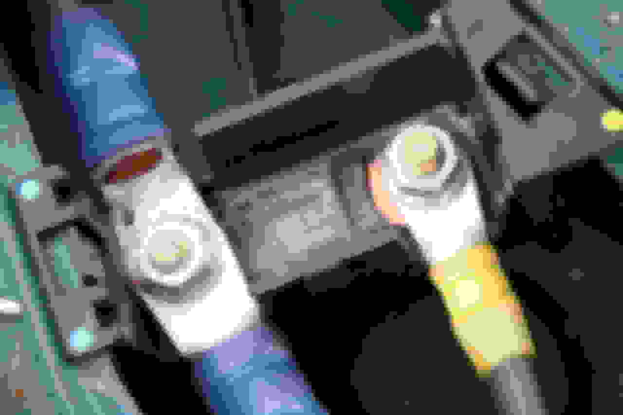
Here's the under seat fuse triangle foam cover. It can just be lifted out, it's not glued in.
Here's the fuse that sits underneath. As you know, the main starter/charging cable (Blue) is not fused here. The other cable (Yellow) feeds the fuse boxes on the heelboard and in the engine bay.
The blue cable exits from the fuse here though a box section in the chassis and appears in the boot on the RH side of the fuel tank.
You can see the cable coming in to the boot at the top of this picture. (NOTE this is on my X308 bodyshell X300 but I'm 99% sure it's the same).
OK I've replaced the OEM engine ground strap with a new OEM unit, and added another 4 gauge battery cable ground from the alternator bracket bolt to the frame of the car.
The only other step not yet performed was to disconnect, clean and tighten the chain of positive/charging cable studs from the alternator to the battery. However I did perform both a continuity and impedance check of that chain from battery to alternator and it was good.
So since the studs in the positive/charging cabling I could see were very clean and noting the above testing, I thought I'd give the car a try.
I took the car down to a local store about 3 miles away, long enough to the engine warmed up, and it ran perfectly, no stumbles or low charge at idle. I parked it for about 15 minutes at the store, then got in and it started right up and ran great for another couple miles to the office. As I pulled into the lot, throttle "closed" coasting into the parking spot, but not in park.... it stumbled and died. It had enough power to turn over, it almost fired when turned over but didn't want to run.
So I went inside and waited about 15 minutes to try again. When I tried to start it again, it again stumbled a bit but I "pumped the accellerator" while cranking, and it then stumbled started, then immediately fell into a good idle and charge. It ran fine all the way home and didn't stumble at any of the 5 other stops (lights, signs, turns) along the way.
So I guess I'll have to check the connections/studs on the positive charging cable after-all before ruling that out, but this is making me wonder if it is purely an electrical problem.
Reviewing . I did get spin test done on my new IN221 voltage regulator when the Ebay item ordered was a new IN435 . Failed on regulator
We're you able to monitor the voltage meter needle and see it go low . For a quick glance read you can mark the gauge with some masking tape with the tape on the high side you never expect it to be so you don't have to focus on it too long .
If never a charge light I would focus on the B+ cable run you mention .
Could it be a open cell in the battery opening up after the battery warms up ?
Last edited by Lady Penelope; 02-19-2018 at 03:20 PM.
You can bypass the fuses by putting the terminals together and give it a try as you have visually inspected terminals tight . In my opinion you can try this if you load shed by keeping the cabin heat blowers off , headlights off , rear window defrost off , seat pan heaters off , cabin air control panel off .
The voltage meter needle and the charge light monitoring signal come straight out of the voltage regulator on the same wire with some connectors in between . But you have a real power and not a sole indication problem as it is reflecting what it is seeing .
Where did you source and brand the latest generator ?
Below 11.5 volts the ECU acts up and should not start .
If you want to look at that voltage regulator power source as it regulates the excitation field windings , look under the fuse box and there is a connector under there that is a prime location for corrosion and may be heat dependent . Corrosion would inhibit the needed current without blowing the fuse which is also demanded by all the other things tied into that fuse . If you want to take power straight to the regulator just pull it off the fuse box terminal post and cut , isolate from all the other systems including the fuse box connector and then splice into the round connector wire.
Last edited by Lady Penelope; 02-19-2018 at 05:27 PM.
When I replaced my alternator the charging voltage increased a little but not enough to keep the battery charged. I checked the voltage at the alternator and it was correct at around 14.4 Volts but at the battery was barely over 12 Volts.
I took apart and cleaned all the connections in the lead from the alternator to the battery and found all of them to be loose and around the firewall stud there was evidence of high resistance and localised heating, the plastic insulator had burned a little and softened and deformed.
After cleaning and reinstalling all the connectors the charging voltage at the battery was up where it should have been at 14.4 Volts so I was losing about 2 Volts in the battery lead due to to poor conductivity in the various connectors.

 02-10-2018, 09:56 PM