When you click on links to various merchants on this site and make a purchase, this can result in this site earning a commission. Affiliate programs and affiliations include, but are not limited to, the eBay Partner Network.
I was a little bit looking into the wiring, but it's pretty old and I found for the moment just the connections for cars with 2 batteries. Also some names for the modules used in wiring are different from names of modules in description. Junction box dual battery is name for the PSDB (power supply distribution box) and Module Gateway for GWM is more common.
So it seems that this connector carry a Lin-Bus wire signal what would explicate the disabling of the spoiler switch. Also a FET Diagnostics line, that seems to have no effect as missing.
More interesting is V-Bat2, so the second battery voltage seems to be tested in the GWM and this explicate also that for the Eco Stop disabling the pull of the plug generates no error as a simple analog signal is provided. So in general it seems that it should be enough to disable this wire. It seems also that the colors have changed over time. But sure is, the wires from the PSDB where is our small black plug, will go directly to the GWM module. If somebody could find a newer version of the F-Type electric wiring, possible to find out if something else changed.
Now I think that on the one battery system, V-Bat2 different from V-Bat1 will always exist. But instead of using a second battery, the voltage is generated from the one battery by a DC-DC converter who makes a steady 12?Volt from a dropped 10?Volt. That is very easy and common today with small electronics and possible all inside the box with the small black plug.
Yes, but the principle is near the same. On the 2 batterie system you have a second battery and on the one battery scheme you have a virtual second battery created by a dc dc converter that generates a stable 12V from an overcharged primary battery in starter modus. Main point is that there is no bus envolved, as the voltage go directly inside the GWM module. I just search for a more sain way to disable the Eco as pulling the plug. I will continu to search for a wiring past 2016 with the one battery system. But it seems pretty sure that the gateway module is the point. If it will be possible to switch the V-Bat2 voltage wire by a remote control, the Eco stop becomes just at choice from the driver. For all VAG cars this works and I appreciate the possibility if I am waiting at a location for longer time, to be able to switch the Eco stop back into normal working condition.
I also found a picture about the VQM where we pull the plug.
Last edited by Cleantex; Feb 12, 2020 at 04:01 AM.
Reason: Picture
Thank goodness for this thread. I carried out the instructions to the letter and voila! No more annoying stops. It just makes the car so much more pleasurable. Thanks for the information!
I still want to work on an upgrade with remote control. It will arrive this days. I know that the V2bat is connected to pin 2 of GWM, but first must find the location of the GWM :/
If the wire on pin2 tells me the color or the connection on the plug of the voltage quality module, the rest is peanuts. What I still not know is if the wiring for the one battery system is exactly the same as before. If somebody could provide this plans, this would be a help in some step forward.
Last edited by Cleantex; Feb 16, 2020 at 12:28 PM.
I have drawings for the 1 battery plus dcdc convertor... Is that what you are after?
It may be easier to just disconnect one wire at a time from the signal connector to identify the one that gives you the desired effect.
As these are signal wires the only, an undesired effect should be a warning on the dash instrument cluster that comms have been lost on the bus to the VQM etc.
That would be nice if there is also the GWM on the diagram and a version with Eco Stop and one battery. All that I have found on the web is earlier 2016. To identify the second voltage connector is not such easy when it is unplugged. Because the GWM send a signal over lin bus to the VQM to generate the Start/Stop voltage. So there is , I think, no voltage on the cable as long it is not demanded by the GWM. With second battery it was just connected during the stop.
Eco Delete different trunk configuration F-type model year 2015
i would like to show a different type of trunk wiring,different to what has been shown here before, my car an F-type S, 2015, has this wiring, no rectangular box, with the purple wire connector to unplug, it has the battery backup. Any help in where to find the Eco connection to disable the stop and go function will be greatly appreciated, it drives me nuts.
TRUNK- MODEL YEAR 2015 F-TYPE COUPE license plate panel -MODEL YEAR 2015 F-TYPE COUPE
You have the two battery set-up (pre 2016).
The secondary battery is visible at the bottom of the first pic (on the RH side of the trunk (boot), right at the back tucked under the trim panel).
No plug to remove, instead you undo and tie up out of the way the earth (ground) lead that runs from the negative terminal of that secondary battery from where it bolts to the floor of the trunk (boot).
Again you can see it in the first pic, roughly parallel and to the right of the emergency hatch release.
Or you can go the whole hog like I did a few days ago and completely remove the secondary battery, same result.
Thank you Oz for your quick reply, I will proceed with it now and post how did it go, Greatly appreciated reply to my reach out for help, this forum rocks!
Yes, but the principle is near the same. On the 2 batterie system you have a second battery and on the one battery scheme you have a virtual second battery created by a dc dc converter that generates a stable 12V from an overcharged primary battery in starter modus. Main point is that there is no bus envolved, as the voltage go directly inside the GWM module. I just search for a more sain way to disable the Eco as pulling the plug. I will continu to search for a wiring past 2016 with the one battery system. But it seems pretty sure that the gateway module is the point. If it will be possible to switch the V-Bat2 voltage wire by a remote control, the Eco stop becomes just at choice from the driver. For all VAG cars this works and I appreciate the possibility if I am waiting at a location for longer time, to be able to switch the Eco stop back into normal working condition.
I also found a picture about the VQM where we pull the plug.
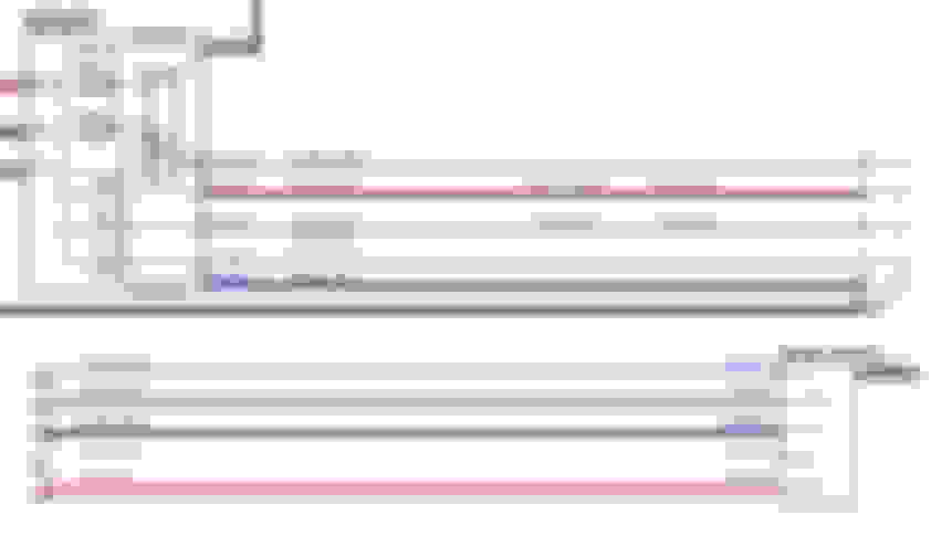
ToPix is such a nightmare to navigate...anyway, the DC DC convertor VQM schematic responsible for the acting as the second battery in earlier cars, is below: Cars without second battery.VQM
I would be inclined to try lifting the Purple/Wh wire 318-4. This is the Sig input from the Gateway Module.
ToPix is such a nightmare to navigate...anyway, the DC DC convertor VQM schematic responsible for the acting as the second battery in earlier cars, is below: Cars without second battery.VQM
I would be inclined to try lifting the Purple/Wh wire 318-4. This is the Sig input from the Gateway Module.
Hi,
First thanks alot for your posting.
Did you also found in Topix not far from this picture the Gateway module (GWM) with the connections to it ?
This would clarify even more the relation between both.
I agree that the purple/white could be the signal on the Lin Bus, but to the VQM, what we need is the feedback
to the GWM. Do you also have this picture larger with the labels ?
Last edited by Cleantex; Feb 19, 2020 at 01:19 PM.
Unfortunately after many hours of hunting, I can't seem to find the internal block diagram of the GWM.
I know where it is located, and what it looks like and it's hooked up tot he MS and HS bus, but can't seem to find the internal electronic schematic which is what we want.
Anyway, here is as much as I can dig up....
I have uploaded a detailed .pdf for the GWM operation: Battery, Mounting and Cables - Battery and Cables Description and Operation.pdf
Anyway thanks to you,
the rest will be digging on the car, but the pdf has some value for this.
I agree, Topix is a nightmare and cannot understand the secret that Jaguar
makes about their cars electric, even Spacex is more open with informations.
Also the funny story is that the colors of the cables om the car have not changed
with the move to the single battery. But on the schematics is different.
You dont have the green/white cable that exists in the real world.
Last edited by Cleantex; Feb 20, 2020 at 03:35 PM.
I have now a copy from the manual of the MY19 electrical diagram and see more on the relation between VQM and the GWM. So, as you can see, the Vbat2 for the (virtual) second battery is always existing on the 1 battery system, but the wire take not its origin in the VQM (as it was green-white before) but in the CJB. And this connection is going over a fuse named PF26.
So it seems that pulling this fuse or remote controlling it may be another option. What I cannot understand, where to find the description of all the fuse in the F-Type ???
Somebody has the answer ? It should be minimum in the workshop book, every trash car has this in the user manual.
I catched today a few more infos, as the seller of the manual send me a description of the fuse boxes.
So, the PF26 is on the A Pillar, passenger side. I will test by pulling it, but for the moment car stands in garage very near to this side.
So, will need some time and good weather.
Hey Tel,
mine is a 2017 SAWD and when look in in the boot this module is on the far LEFT side, (drivers side, US)
it LOOKS the same from your picture, is it the same?