
Solved!!! Resistors w/ LED installs

Thread Starter
|
Veteran member


Joined: Mar 2007
Posts: 11,345
Likes: 1,166
From: Oak Ridge, TN
I replaced the turn signals and brake/stop lamps with some LEDs, but of course, it is causing a couple problems with the electronics.
(1) Car thinks there is a bulb problem, so 'quick' flashers inside
(2) When I press the brake, the bulbs dim after a couple seconds, also presuming having to do with the new bulb load
So, I am either going to add load resistors or a new flash relay or these http://www.superbrightleds.com/flashers.htm
Wire splicing, is not my preferred method of correction, as the wiring harness on the tailight assembly will have to be looked at pretty closely to figure out which wire is which. I prefer the easy relay replacmeent, but need to know if this type will work, and how many I need. One for turn signals, one for front one rear? What about the brake dimming problem..., and where are these relays located.
[sm=helpout.gif]
Thread Starter
|
Veteran member
Joined: Mar 2007
Posts: 11,345
Likes: 1,166
From: Oak Ridge, TN
I found the fuse/relays in the battery 'bay', but the manual doesn't state which relay is for which component. I'm googling, with little luck.
Thread Starter
|
Veteran member
Joined: Mar 2007
Posts: 11,345
Likes: 1,166
From: Oak Ridge, TN
Managed to find an old XK8 electrical manual online, which shows me the color of the wiring for the brake/stop and turn signals. I still can't find the location of the turn signal relays...sounds like under the steering column..so hoping someone could help me there.
Matt
Matt


Joined: Jan 2008
Posts: 2,961
Likes: 89
From: 33498
Sorry bro but your car does not have flasher relays. Input to Body Processor Module (BPM) from turn signal switch and output from BPM to activate lamps. The tick tock sound you hear that is like the old flasher relay cars is created by BPM to sound that way. Studies showed that people were more comfortable hearing the tick tock noise when turn signals on.
Thread Starter
|
Veteran member
Joined: Mar 2007
Posts: 11,345
Likes: 1,166
From: Oak Ridge, TN
Ok, so I got the project ALMOST finished. The turn signals I got working just fine with the new LEDs and load resistors installed, and I am in the tail lamps, upgrading the single tail/brake combination bulb - 1157.
I plan on posting another thread, just as soon as this is finished, with a thorough writeup about what is the best to use, and errors that I learned the hard way.
So, back to my tail lights. This is a schematic of my Left Tail Lamp wiring harness and where I have currently installed load resistors.
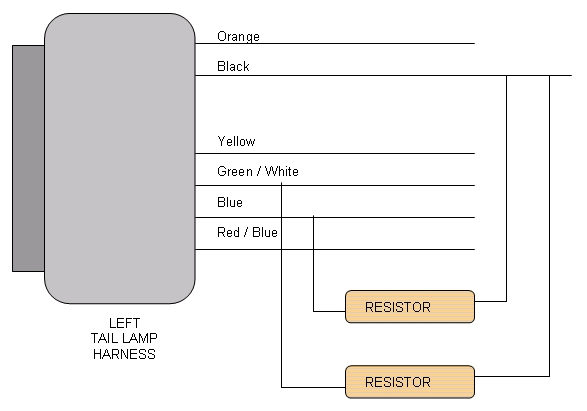 [ul][*]The turn signal wire is the Green / White wire. As I said, that one was figured out testing the bulb mount for the same voltage as the harness.[*]The brake/indicator bulb is charged by both the Blue and Red (on 1s click of the stalk)/ Blue *brake applied*
[*]Orange - Rear Fogs, tested by the volt meter
[*]Yellow - Reverse Lights, by process of elimination
[/ul]Not that this helps me, but each resistor is a 6ohm, 50 watt unit. A filament bulb uses 2 amps, so they say. But is that double for a double filament bulb?
Here is a schematic of the LEFT Tail Lamp for reference on my second question.
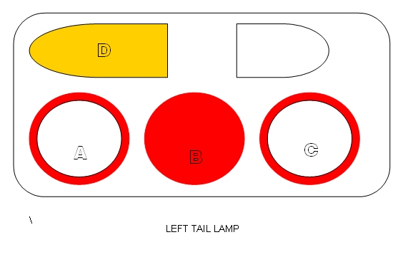
LEDs are installed in bulb mounts in A, C and D
OK, Now the Turn Signal (D on the schematic) uses a 1156 (single pole) bulb. Again, no problems with this one.
A - Brake / Parking Indicator, uses a 1157 (two pole) bulb
B - Parking Indicator, uses a 1157 bulb, but only has on one contact in the bulb mount. Basically, it is only on (dimly) when the lights are turned on.
C - Fogs, uses a 1156 bulb. Operated by the 'rear fog' button on the console, no message show up when I turn them on.
Now, the instructions with the load resistor says to install it on the BRAKE/TURN wire of the 1157 bulb, which is what I tried. I had the brake applied, no 'parking' or indicator bulbs on...just the brake. I tested the bulb mount and found the voltage of one of the two poles..the only one that would register, leading me to believe that the Blue wire was the brake lead. So, resistor tied on that one and check of the instrument warning area. When I now apply the brake, no "CHECK REAR LIGHTS" comes on. So far so good. But when I turn on the indicator lamp/parking light on the stalk (1st click), I get the message instantly. I'm miffed.
Thinking out loud...two bulbs illuminate in the lamp when I turn on the parking lights. A and B both. Only one wire on the harmess puts out 12+ volts, that is the Red / Blue wire. It must be energizing both bulbs. So, I tried to put another separate resistor on it.
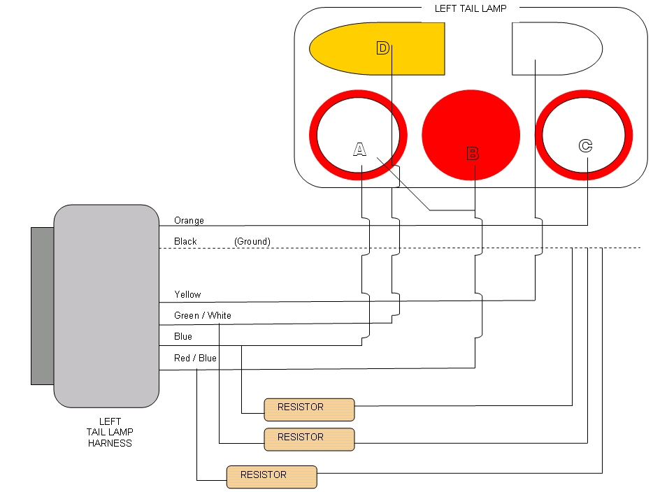
Still no luck. Maybe the same resistor that is on the Blue wire must also be on the blue / red wire, not separate. Does that make sense? Any electrical wizzes out there to help me out. I've spent 2 full days trying to diagnose and solve these LED install issues, i'd like to fnish it up with fixing this last little hurdle.
For now, it stays as is, and I clear the message when I turn on the lights at night. Need help. [sm=headbang.gif][sm=dontgetit.gif][sm=headbang.gif]
I plan on posting another thread, just as soon as this is finished, with a thorough writeup about what is the best to use, and errors that I learned the hard way.
So, back to my tail lights. This is a schematic of my Left Tail Lamp wiring harness and where I have currently installed load resistors.
[ul][*]The turn signal wire is the Green / White wire. As I said, that one was figured out testing the bulb mount for the same voltage as the harness.[*]The brake/indicator bulb is charged by both the Blue and Red (on 1s click of the stalk)/ Blue *brake applied*[*]Orange - Rear Fogs, tested by the volt meter
[*]Yellow - Reverse Lights, by process of elimination
[/ul]Not that this helps me, but each resistor is a 6ohm, 50 watt unit. A filament bulb uses 2 amps, so they say. But is that double for a double filament bulb?
Here is a schematic of the LEFT Tail Lamp for reference on my second question.
LEDs are installed in bulb mounts in A, C and D
OK, Now the Turn Signal (D on the schematic) uses a 1156 (single pole) bulb. Again, no problems with this one.
A - Brake / Parking Indicator, uses a 1157 (two pole) bulb
B - Parking Indicator, uses a 1157 bulb, but only has on one contact in the bulb mount. Basically, it is only on (dimly) when the lights are turned on.
C - Fogs, uses a 1156 bulb. Operated by the 'rear fog' button on the console, no message show up when I turn them on.
Now, the instructions with the load resistor says to install it on the BRAKE/TURN wire of the 1157 bulb, which is what I tried. I had the brake applied, no 'parking' or indicator bulbs on...just the brake. I tested the bulb mount and found the voltage of one of the two poles..the only one that would register, leading me to believe that the Blue wire was the brake lead. So, resistor tied on that one and check of the instrument warning area. When I now apply the brake, no "CHECK REAR LIGHTS" comes on. So far so good. But when I turn on the indicator lamp/parking light on the stalk (1st click), I get the message instantly. I'm miffed.
Thinking out loud...two bulbs illuminate in the lamp when I turn on the parking lights. A and B both. Only one wire on the harmess puts out 12+ volts, that is the Red / Blue wire. It must be energizing both bulbs. So, I tried to put another separate resistor on it.
Still no luck. Maybe the same resistor that is on the Blue wire must also be on the blue / red wire, not separate. Does that make sense? Any electrical wizzes out there to help me out. I've spent 2 full days trying to diagnose and solve these LED install issues, i'd like to fnish it up with fixing this last little hurdle.
For now, it stays as is, and I clear the message when I turn on the lights at night. Need help. [sm=headbang.gif][sm=dontgetit.gif][sm=headbang.gif]
Trending Topics
Thread Starter
|
Veteran member
Joined: Mar 2007
Posts: 11,345
Likes: 1,166
From: Oak Ridge, TN
Since I love updating my own thread, and don't know if anyone is really following this one or not, I decided to finish it.
I was having problems with the CHECK REAR LIGHTS message coming up on my display, and I thought it was due to an incorrect install of the resistors on the wiring harness that was related to the LED bulb socket. Well, during LED install and testing, one of my P21W bulbs in the tail lamp went out, the one next to the brake bulb (the one that is always on, just dim), and I replaced it with an aftermarket 1157 bulb, perfect fit and function right? Well, the message comes up, and I decide to start over...put all the old filament P21W bulbs back in, except the 1157 remained, because the old one was burned out.
When I turned on the key to the 'accessory position' right before ignition, the message would not appear. As soon as I nudged the key further...ignition, and the message appeared...so I got to thinking. Another member had trouble replacing his light bulb with an aftermarket, and had to get a dealer one to clear his message. Well, I thought that maybe the P21W bulb and the 1157 bulb have different levels of resistance, causing the computer/module to still think that the bulb was out, but why after startup, and not pre-ignition??? So, as an experiment, i put a load resistor ON this wire as a test. And it worked! No more messages!!
[sm=groupwave.gif]
So, in goes all of the LEDs, and their own resistors, and it works perfectly. The red/blue line gets two resistors in series to act for the LED and the replacement 1157 bulb. It now makes all the sense in the world.
Final Wiring diagram...promise.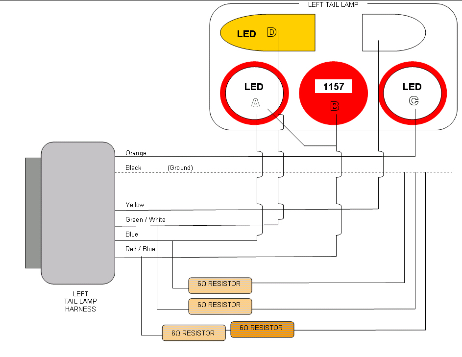

Thread Starter
|
Veteran member
Joined: Mar 2007
Posts: 11,345
Likes: 1,166
From: Oak Ridge, TN
Working on a video to put on u-tube with some still shots of the resistor install locations. Hope to have up next weekend.
Thread Starter
|
Veteran member
Joined: Mar 2007
Posts: 11,345
Likes: 1,166
From: Oak Ridge, TN
Another tidbit of resistor information.
From Thermo:
"the size of the resistor is kinda trivial really. There are 2 specs that you need to be interested in. First spec is the resistance of the resistor. For our cars, at a maximum you want a 20 ohm resistor. This will be enough combined with the loading of the LED bulb complex to not trigger the fast flash. The other spec is the wattage rating of the resistor. This is what normally determines the size of the resistor. The resistor is going to pass some amount of current through it. You can calculate the power requirements of the resistor simply by squaring the voltage of your car system (typically 14.4 VDC) and then dividing it by the resistance of the resistor. So, ultimately, you are going to need a resistor with a power rating of 14.4 x 14.4 / 20 ohms, or 10.36 watts (a 10 watt resistor will be just fine). If you use a 10 ohm reisistor, then you simply subsitute in the 10 ohm in place of the 20 and you will need a 20.72 watt resistor. The higher wattage resistor is going to be bigger so it can dissapate all that heat. You can get away with say a 10 ohm 10 watt resistor for a short period of time as the bulb is not energized 100% of the time (actually only about 50% of the time), but the cycling of the heat can lead to premature failure. So, get the larger wattage resistor and save yourself a lot of heartache later on."
"the size of the resistor is kinda trivial really. There are 2 specs that you need to be interested in. First spec is the resistance of the resistor. For our cars, at a maximum you want a 20 ohm resistor. This will be enough combined with the loading of the LED bulb complex to not trigger the fast flash. The other spec is the wattage rating of the resistor. This is what normally determines the size of the resistor. The resistor is going to pass some amount of current through it. You can calculate the power requirements of the resistor simply by squaring the voltage of your car system (typically 14.4 VDC) and then dividing it by the resistance of the resistor. So, ultimately, you are going to need a resistor with a power rating of 14.4 x 14.4 / 20 ohms, or 10.36 watts (a 10 watt resistor will be just fine). If you use a 10 ohm reisistor, then you simply subsitute in the 10 ohm in place of the 20 and you will need a 20.72 watt resistor. The higher wattage resistor is going to be bigger so it can dissapate all that heat. You can get away with say a 10 ohm 10 watt resistor for a short period of time as the bulb is not energized 100% of the time (actually only about 50% of the time), but the cycling of the heat can lead to premature failure. So, get the larger wattage resistor and save yourself a lot of heartache later on."


Thread
Thread Starter
Forum
Replies
Last Post
Currently Active Users Viewing This Thread: 1 (0 members and 1 guests)