When you click on links to various merchants on this site and make a purchase, this can result in this site earning a commission. Affiliate programs and affiliations include, but are not limited to, the eBay Partner Network.
Looks like you are right about them being TTY bolts. From the manual:
"Torque to yield bolts must be discarded and new torque to yield bolts installed unless otherwise stated within the procedure, recognizable by a tightening torque with more than one stage together with a torque angle".
I appreciate the willingness to discuss, often times these threads dissolve into valueless arguments when questions are asked. Just my opinion, but I would be concerned that using the new fasteners may have resulted in a change to the clamping force on the mains (42lb-ft +70 degrees vs 60lb-ft) which necessitates line boring/honing the crankcase. I'm sure there is a calculator out there (or someone smart on the board) who can calculate the equivalent torque for the 42lb-ft +70 degrees and compare it against what ARP specify for their studs. If there is no significant difference I can't see why the line boring would be required. If there is, you could be changing the stiffness of the crankcase in that area which could change it's response to loads. Is there any information on the Jaguar bolts that might indicate the material used?
I understand what you're saying, however, "davetibbs" was measuring the roundness of the main bearing saddles AFTER checking them with the ARP studs installed and torqued to spec. Maybe I missed it, but I didn't see where he measured that dimension when the OE bolts were securing the main caps. Therefore, it's possible that the saddles were out of round right from the "get-go". While certainly not perfect, that IS a small number, possibly maybe even within spec.
I understand what you're saying, however, "davetibbs" was measuring the roundness of the main bearing saddles AFTER checking them with the ARP studs installed and torqued to spec. Maybe I missed it, but I didn't see where he measured that dimension when the OE bolts were securing the main caps. Therefore, it's possible that the saddles were out of round right from the "get-go". While certainly not perfect, that IS a small number, possibly maybe even within spec.
Correct. I'll probably torque a main bearing cap up with factory bolts to spec to see how it compares.
Very small update, while the beast sits sad and lonely as I rebuild the engine (far too slowly) I decided to make it look a bit less sorry for itself. A bit.
At the moment it's primed but I'll wait to get it painted, so I've covered it in plastidip to protect it until the car is up and running again.
(the headlights are missing as I'm doing a cheeky bit of work to them too)
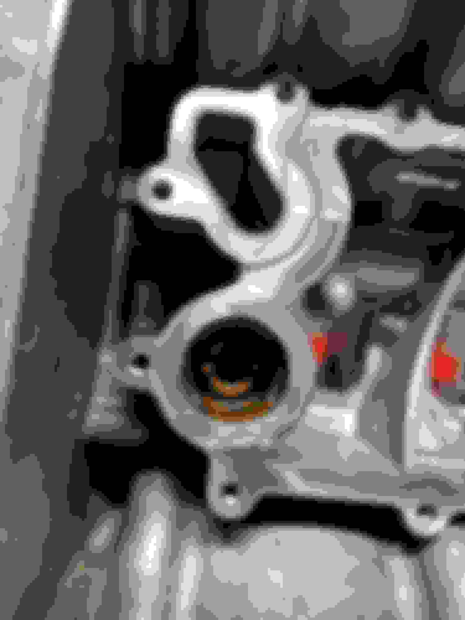
So this is a weird one. I've been trying to replace anything "while I'm there" on this rebuild like seals, O rings, etc, and one of the things that I've found is this:
It's an oil non-return valve that's fitted under the oil cooler, and I can't find one anywhere. Obviously it's tricky to find parts listings for pretty much any internals in the 5.0 engine, but I have this diagram of the 5.0 NA engine block from an odd Russian Land Rover parts catalog website and you can see it marked 6C571:
That shows the part number as "LR012974" but I can't find any reference to this part beyond links to that site. The SC block diagram from the same website doesn't even show the valve on the diagram. I found another site that had the image of the valve grayed out. Sites like lrdirect.com have no reference of that part number. I've tried Google image searching for it, with no luck.
Anyone got any ideas where I might be able to source these? JLR don't make any of their own parts, so someone else made this and they must be possible to buy, but I'm pretty stumped.
Incidentally, if anyone can suggest a way I can remove this without damaging it, there may be some identifying marks or numbers on the bottom, but I doubt there is.
I guess the bigger question is - mine is fine, I assume everyone else's is. But what happens if one breaks?
perhaps you can find a similar check valve across the Ford product range
as these engines are build by Ford.
Regarding the notch on the upper part of the check valve I suppose it might
be screwed to the engine block with a special tool engaging in this notch.
Worth a test whether it can be turned (carefully) .
Since I've read alot about the timing chain issues of these engines I could
not find serious information about the design of the hydraulic timing chain tensioners.
There should be a "ratchet mechanism" inside , but no glue how it works and how
to reset this mechanism when reinstalling them .
Dave , can you give me some advice ?
Regards
Ulrich
@davetibbs...Been following this thread for a while. Awesome learning experience for me and it has helped me visualize alot of things for my own project.
Here is the approach I would take (incorporated into my personal philosophy by hanging out with old geezers during my childhood):
-Can you break it?
-Is it broke?
IF the answer to those is Yes and NO....don't **** with it. As much as I feel your need to take that little f%$^ing thing off just to see how it works, it seems you have no source to replace it if it breaks on you. I will take this to the dealer service guys when I drop by this week and see if they know where to get it or even what it is.
Thanks - and for what it's worth, I completely agree. I'd never take it out just to see how it works, but I'd like to replace it with a new one if I can because it just makes sense. Obviously if I can't find one I'm leaving well alone.
perhaps you can find a similar check valve across the Ford product range
as these engines are build by Ford.
Regarding the notch on the upper part of the check valve I suppose it might
be screwed to the engine block with a special tool engaging in this notch.
Worth a test whether it can be turned (carefully) .
Since I've read alot about the timing chain issues of these engines I could
not find serious information about the design of the hydraulic timing chain tensioners.
There should be a "ratchet mechanism" inside , but no glue how it works and how
to reset this mechanism when reinstalling them .
Dave , can you give me some advice ?
Regards
Ulrich
Sure, although I haven't actually fitted new tensioners yet. They have a spring inside with a ratchet mechanism, and a pin to hold the tension until it's needed.
I've attached the relevant workshop manual section, and here's a video from the online workshop manual to illustrate the action:
So for those who were interested in this thread, I haven't died, and neither has the project....yet. (Though it's felt close to it sometimes).
At the moment it seems I'm perpetually in a situation of awaiting parts (pistons/rings which are due any day now, and line-honed conrods with ARP bolts), then I need to get the crank polished and balanced but I'm close to being able to start building the block back up, and then it's all systems go to get the engine built back up as frankly, I want my ****ing car back.
I've got lots of new parts sat awaiting engine reassembly
And since it seems unfair to drag this thread back up without anything of substance, have a teaser photo of something I was going to wait to reveal but I'm quite excited about: custom oil temperature, pressure, and boost gauges designed to match my factory instument panel, made by New Vintage USA. The quality is fantastic - the paint is silver like the factory gauges, and I haven't had a chance to compare the backlight color but it looks pretty good from the photos they sent of them illuminated.
I'm planning on some custom dash work to mount these but that can come after the engine has been rebuilt. As for why I got them: I'm not putting this much time, effort and money into rebuilding this engine without having some sort of a telltale as to if it's going to break again!
If anyone else is interested (though you might want to see how the dash gauge mounting goes first, lol) I'm sure they've kept the design files to make more.
Dave, I closely following this thread. with such effort,and complete dissasembly i think you could went for custom engine( custom rods, crankshaft) uprated components from ford(same zf) gearbox after remap and both pulleys you should have some seriuos (850-900HP ) and RELIABLE power built to last more than youngsters mitsubishi evo or subaru which is built for few races.
Again this is NOT a Ford engine and NOTHING from the 5.0L Ford engine swaps over the JLR 5.0L V-8.
They are completely different engines.
To clarify, I think elviukai's point about Ford refers to the gearbox and not the engine - the Ford 6R80 is based on the ZF 6HP26 but has upgrades like a thicker input shaft allowing the gearbox to handle higher engine power output once you fit uprated clutches etc - this means it's possible to swap the 6R80 internals into the 6HP26 (with some mix-and-matching of things like the torque converter) which would likely be required once you break into the power figures he's talking about.
My problem with this is even if you uprate the engine and the gearbox, you're likely just making the rear diff the weak link in the chain, and I don't fancy the costs of upgrading that.
elviukai brings up a good point though. Would there be any way to throw in forged components into the block before you assemble it again? I assume, as with all thing Jaguar, there are no sources of parts for our engines and that is probably why @davetibbs has not upgraded any internal engine components. Nice gauges btw...way nicer than what is currently in the XF dash...hopefully you wont have as much trouble as I have finding a signal for those...lol
Last edited by Cherry_560sel; 12-28-2017 at 10:08 PM.
probably why @davetibbs has not upgraded any internal engine components.
Who said I'm not upgrading internal components?
The lack of parts availability is precisely why I'm awaiting custom forged pistons, and I'm also using ARP fasteners internally. However, I don't have an unlimited rebuild budget and since the factory conrods are forged anyway, I didn't really see the point of having custom rods and crank made as well. I'm not planning on putting stupid power out of this engine.
I couldn't agree more. I could've done a pretty good job on an A pillar, moulding the gauges in and having it recovered in the same material as factory, but this is a Jaguar XF, not a Subaru Impreza, EK Civic or Foxbody Mustang
Since my dash top leather is screwed like everyone else's my current plan is to pull it off and mould the 3 gauges into it above the infotainment (I hate myself for using that word) screen, pulling the tops back and smoothing them in like the XJ air vents. I can then get it (and the four matching door cards) covered in the same color alcantara because racecar. I'm hoping I can have it look reeeaaaasonably factory, but I really haven't found any other options that work for me.
davetibbs if anybody can do this and have it look decent it will be YOU!
Thanks again for your in depth and very detailed posts.
They are a treat to read!
Just wish I could do anything at that level. I feel great just doing repairs and maintenance UNTIL I read what your up too!
.
.
.
 09-21-2017, 04:52 PM