When you click on links to various merchants on this site and make a purchase, this can result in this site earning a commission. Affiliate programs and affiliations include, but are not limited to, the eBay Partner Network.
Premium ICE head unit install with factory amp (Success)
Abracadabra
Houston we have lift off!
With help from: Ric in RVA, Lady Penelope (It’s a dude) haha & SleekJag12 a head unit has been successfully installed while maintaining the factory amp and it sounds perfect!.
I would like to start by thanking them, with their direction and a little luck i’m excited to say we have bluetooth, dvd, tuner, monitor outputs (head rest or any external lcd screen you’d like to mount) aux input and backup camera all in a single din package.
Total time including testing (4 hours), You should be able to pull it off in 1-2 hours
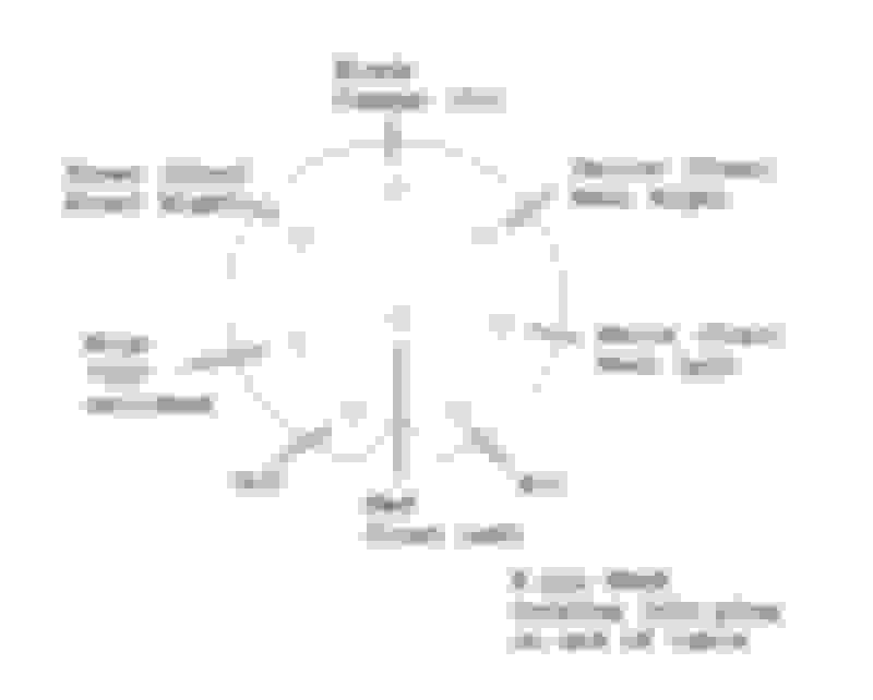
8 pin din connector to CD player, It is very easy to tap the low level audio lines to give yourself bluetooth or an AUX with the factory Alpine however getting the CD changer to work with an aftermarket is impossible (for me at least). I do have the pin out if you'd like to try. The radio and CD changer communicates through a “CAN BUS”. I don’t have the the time to sniff the bus line and find out how it works. I did get you the pin out though, something I don’t believe anyone has or at least has provided for me. Maybe someone could build off my work here
Now onto the good stuff.
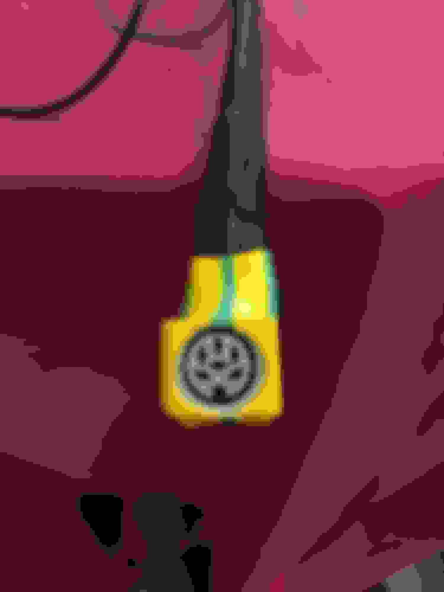
Tan 5 pin din
Blue = rear drivers side
Red = rear passenger
Yellow = front drivers side
Black = front passenger
Green = Ground - should be connected to the chassis ground not the radio ground speaker wires if there's an alternator hum or squeal
This system uses a common ground so grounding the radio is all you need to do. You will not use the striped leads from your new head unit only the + solid speaker leads.
Just for definitive clarification these are NOT low level line inputs they are high level inputs (DO NOT USE THE RCA’S) unless you want to add a secondary amp for a sub on top of what we’re doing with the tan 5 pin din
White connector
Pins you will use, at this point most of the colors will align with the aftermarket head unit and the new harness
Car Harness/Aftermarket Radio
Pin 1 - Y/Y
Pin 5 - LGB/Blue - This pin hooks to the power antenna output from the new head unit it turns on both the factory amp and power antenna, woo hoo!
Pin 11 - R/R Switched +12v
RW and RO are poth non switched +12v if you need to power something else like a dash cam, gps etc.
You will not be using pins 6, 7, 8, 9, 12, 14, 15, 16, 17, 18, 19 or 20 with the ICE setup. You will still need the normal setups (NON ICE) harness to keep from cutting wires. Part #
is the Dash/Rear cam DVR rearview mirror setup. The head unit has reverse cam, dvd, tuner, bluetooth and an aux. all in a single din. The dvd plays on the tiny screen you see in the video
Can you post an "after" pic using the approximate same angle and lighting as the "before" pic? (I was all atwitter with excitement at discovering someone had accomplished fitting all those features in a neat, OEM-like appearance, having rapidly scrolled down through all the wiring discussion and schematics to find an install pic.....then decided it looked a bit "too" OEM-like, and noticed the "before" tag)
Depending on the status of your speakers and whether you plan on repairing them , double check the size as mine are the non - premium and the dimensions given in the pic are for that .
I'm suppose to rewire someones X300 premium setup stereo system ( and engine regulation ) as the previous owner has slaughtered the wiring attempting to put in a aftermarket head . I will get the dimensions for it's speakers when he ever shows up for his appointment with me ( ? ) . The non - premium door speakers are branded Philips as a labeled LNA4140 B A part number and the premium according to this website is different as LNA4140 A A .
Can you post an "after" pic using the approximate same angle and lighting as the "before" pic? (I was all atwitter with excitement at discovering someone had accomplished fitting all those features in a neat, OEM-like appearance, having rapidly scrolled down through all the wiring discussion and schematics to find an install pic.....then decided it looked a bit "too" OEM-like, and noticed the "before" tag)
Very nicely done! And so quickly too... Happy to hear that it works and sounds great. Lovely dashcam view over the hood!
Out of curiosity,
How did you figure out that the inputs to the amp are not low level? Did you first try using the head unit's RCA outputs? I never would have thought you could put the positive only speaker outputs to the input of the amp. What about the negative leads from the head unit, are they just tied off unused?
You have also unlocked the secret of the auxiliary input for the original head unit! The Rosetta DIN connector! Thank you for that. YOU sir, are a beast!
Unfortunately for those without the 8 pin line to a external amplifier not used in the standard setup , looking to find a way to get a aux line into the head unit as the speakers final amplifiers are in the head unit . This approach would be more DIY easier then soldier inside .
One of the wires in the tan connector must be a volume control to the external amplifier other then the left and right channel line ins .
Otherwise it is a nice deciphering ( you broke the code ) and installation .
Last edited by Lady Penelope; Jan 27, 2018 at 12:26 AM.
Unfortunately for those without the 8 pin line to a external amplifier not used in the standard setup , looking to find a way to get a aux line into the head unit as the speakers final amplifiers are in the head unit . This approach would be more DIY easier then soldier inside .
One of the wires in the tan connector must be a volume control to the external amplifier other then the left and right channel line ins .
Otherwise it is a nice deciphering ( you broke the code ) and installation .
It's actually the tan 5 pin din to external amp, The 8 pin goes to the factory 6 disk so if you have an external CD unit you can use the 8 pin din pin out to add AUX.
If not, the tape head itself inside of the factory radio will have low level inputs red & white then ground to the deck plate to add AUX at this point you would have to put in a dummy tape with no guts to trigger it. It would be a clean option though much better than a tape to aux hanging out of the head unit.
After reading your post again, I think this is what you were saying no?
Last edited by Jacob Hankins; Jan 27, 2018 at 04:40 AM.
Very nicely done! And so quickly too... Happy to hear that it works and sounds great. Lovely dashcam view over the hood!
Out of curiosity,
How did you figure out that the inputs to the amp are not low level? Did you first try using the head unit's RCA outputs? I never would have thought you could put the positive only speaker outputs to the input of the amp. What about the negative leads from the head unit, are they just tied off unused?
You have also unlocked the secret of the auxiliary input for the original head unit! The Rosetta DIN connector! Thank you for that. YOU sir, are a beast!
Yes sir and thank you. I was leary about the low level inputs the more I thought about it. If i was personally designing the Alpine unit for both standard and ICE I would not rebuild the amp circuit just reroute it. I did test the low level's first and was rewarded hearing sound and knowing I got the amp on at least but with low volume. I then went for the high level input and solid crisp sound was the outcome. I am really pleased with the result and am adding a sub and amp right now. I did some investigation into my stock speakers and they look new except for the A pillar tweet, It's blown out completely. I will be fixing this and my clock ASAP!. I really aprreciate the time you guys spent helping me. It will be very beneficial for future readers.
(Ground) You are correct, with a common ground the head units -12 is tied off and unused.
If I can ever help either of you with anything. does not have to be jag related let me know please
Last edited by Jacob Hankins; Jan 27, 2018 at 03:11 AM.
Excellent work and a well-done thread!
End result is a very handsome installation. I'm still partial to maintaining the OEM appearance, but until someone retires to the workshop and adapts the original faceplate and controls to operate a "black-box" head unit with all of the modern functionality, this is as good as it gets! Not jumping into the aftermarket pasture yet, but I have at least climbed the fence....
I was leary about the low level inputs the more I thought about it. If i was personally designing the Alpine unit for both standard and ICE I would not rebuild the amp circuit just reroute it.
An excellent deduction! Makes sense.
I think I'll sit back now and wait for you to replace the tweeters, see how you did it and what you used, then go ahead and copy it! If you don't mind.
I am 100% original at this point too, although left front tweeter doesn't work and the sound is not so crisp anymore. Aside from replacing tweets, I'm not quite ready to make the leap to aftermarket either. But if there are any failures of systems, we now know it can be done. It's gold!
I agree with keeping stock appierence in most classic cars but i have to have a good sounding system. I've produced music for 20 plus years and for me personally music and cars go hand in hand. Last year I bought a Maserati Quattroporte and the first thing i did was rewire the entire sound system. Everyone thought i was crazy but I do good work and am confident I can return them back to spec, I do countless hours of research and would never pull some hack job crap. not that anyone will EVER get their grubby hands on my cars!, haha, I don't sell cars I buy them and they will be mine until I die. I decided tonight to go buy a new head unit that has a dimmer and monochrome green lighting. I am much more please with the aesthetics now as it matches more closely. I am removing the factory sub and adding tweets to the blank grills on the deck lid as well as the pillars, I will be sure to let you know how it goes. The factory mids I can deal with but the highs are sharp in a bad way. I will be installing a seperate hidden micro amp and spending a pretty penny on ribbon tweeters like
Coming back to this for a quick update for future explorers:
The below figure as referenced in post #9 above does not actually apply to this installation. The 8-pin DIN cable (gray) is only used for the 6-disc CD player, and the pinout is different than what is shown here. The 5-pin DIN cable (tan) is used for the external amplifier feed, which does not correspond to this figure.
The diagrams shown in the FIRST post here are correct.
Please DISREGARD the below pinout for this installation.
I decided tonight to go buy a new head unit that has a dimmer and monochrome green lighting. I am much more please with the aesthetics now as it matches more closely.
Thanks Jacob, got any pics of the new head unit with monochrome lighting? Maybe a source/link for the head unit you chose?
The original head unit on my son's 96 VDP got stuck on (IMO) too-high volume, which didn't bother him much...but later became stuck on "OFF" and would not play. After awhile, I replaced it with an OEM head unit I'd retrieved from a Pick-n-Pull car. All good for some months. However, for QUITE a while now, it has been incapable of anything above a whisper volume. On/Off works ok, but volume was only loud enough to be barely audible with the car not running, even at idle. He graduated from High School this spring and will be attending Tarleton State University in August. The wife and I are very proud of the young man. I told him for graduation, I'd fit an aftermarket head unit or have one of our broken OEM ones refurbished. He is a traditionalist, and quite interested in maintaining the original appearance. However, the teenager in him won out after I showed him this post and he decided he'd like the modern amenities of bluetooth and aux-inputs. I gave him this model, and a couple of Alpine media players to choose from that had changeable display colors, but not a screen display as this unit does. After considering it for awhile, and consulting his audiophile older brother, he opted for the head unit pictured in post #6, above.
I sourced it from Amazon on account they were some $40 cheaper or so than Crutchfield's as Crutchfield didn't offer any special installation gear and noted they had no installation tips or fit instructions for this application. I waited until the harness and fascia arrived from Amazon UK to begin the installation, thinking I had everything in-hand to complete. I thought wrong...sort of.
Hate to admit it, but while I intrinsically "sensed" that the purpose of Jacob's post was to inform us how to make an aftermarket head unit work with the premium sound setup....I somehow missed the whole necessity and mechanics of how to access the wires in the "5 pin" connector. Ok, first pet-peeve, it's a 6-pin connector! Yes, only 5 are used, but it has 6. Yes again, not really an issue as the only other connector that it could possibly be is the 8-pin (that actually has 8 pins) CD connector that is well-identified in the post.
Anywho, after I had everything plugged together, pre-installation, for a function test, and was met with silence, I began to study this thread (post #1) more closely. I ran a jumper from the white speaker output on the head unit to one of the pins on the 6-pin. I was rewarded with radio sound, from a speaker of indeterminate location. I recruited the car-owner to help me identify which speaker was working, as I had to maintain position to hold the jumper in-place. He helped me work my way around the 6 pin with the jumper identifying what was what.
Yes! Jacob did an excellent job of identifying what wire color was associated with which # pin and what speaker each was associated with. However, post #1 contains an excellent schematic of the 8-pin with the pins numbered. No such animal for the 6 pin. IF I were cutting the 6 pin off and connecting the wires, it would be easy to just go by the colors. Not in my plan. First order of business in modifications in my world is to do everything possible to maintain backward compatibility. I like to keep the option to always go home again....so no cutting off the 6-pin DIN. Couldn't find a pic like the 8-pin schematic in the wiring diagrams anywhere, either. Where do I find a female, 6-pin DIN connector? Here:
but I found this late afternoon Saturday and I imagined buttoning this thing up before heading back to work on Sunday.
Well....I've got 4 X300 head-units, 2 of which are inoperable, vs. 3 cars, so I could maybe get one off the board. As it happens, we joke about the OH-58D Kiowa helicopter being a transport system for the giant sensor ball on top of the rotor. Take it off and sell the aircraft to law enforcement or for paramilitary use and the aircraft fatigue life is drastically reduced. The ball attenuates significant vibrations within the airframe. I'm now convinced something similar is going on with the OEM head unit. It is a box designed to securely hold the female 6-pin DIN connector!
AFTER I finally got the board it was mounted to free, I found it was protected by a metal stamping running the length of the board, attached by tabs inserted through the board and bent to lock in place, then soldered. Heavily. Additionally, the 6 pin connector was securely soldered to the board using thru-hole methodology with not 6, but 8, count 'em, 8 thru-hole pins!!! After getting 3 of the five metal-stamping pins de-soldered and twisted into alignment to remove, I got frustrated and just peeled the stamping up out of the way on the side that I'd freed-up using a pair of pliers. Continued under-performance of my solder-iron in melting the solder on any of the 8 pins reliably, drove me, board-in-hand, to the bench grinder. I ground the pins off, along with a bit of the board, then applied the solder-iron tip to each pin and (FINALLY!) effected removal.
After several hours worth of attempts, I conceded that I didn't have enough pin-length left to solder a wire to. After a full-night's sleep, I determined removal of the black plastic locking device on the back of the connector was key to liberating enough metal to solder to. Naturally, "removing" the locking device degenerated into an exercise in brute-force and awkwardness resulting in the removal of said device in an array of broken pieces. Fortunately, the female pin molding of the DIN connector remained intact, despite the actual "pins" being scattered all over the work table! Sorry, too involved to take intermediate pictures, but here is what I ended up with:
Naturally, once I got it all together, and was cleaning up my workspace and putting away my tools, I happened upon the microphone, still in it's bag! Ah well, my plan is to pull it all apart in a week or two and replace the home-crafted Female DIN connector with the one that arrived on Monday, after Sunday's re-assembly.
There were other complications, of course, including two broken radio/clock/CCM frames and a no-crank condition upon final assembly that I'll detail later, but for now, this is already too long-winded. The main point is, if backward compatibility is important to you...think about how you are going to handle the 6 pin connector before you dive in.
Very nice install, I love seeing people build off my work as I built off others. It's been a few months now since my original install and I'm pleased to report everything still sounds amazing original speakers and all.
Wouldn't have been successful without your post, Jacob! End result looks the same as yours as it is the same head unit.
Last week, I had some time to remove it and re-install with the recently-delivered 6-pin din and switch the audio feeds so that left on the radio balance equals the left side of the car, and right is right....don't recall if I mentioned above...but with the temporary connection, I'd managed to make right left and left right, even so front and rear were proper in the fader controls, despite our rigorous pin-to-pin testing during development. I think it was a translation mistake from testing the front of the male connector and translating that to the rear of the female connector....should be the same in my mind, but somehow wasn't.
I mentioned the broken mounting bracket...when installed, it was broken at the three climate control mounting bosses, repaired with epoxy, and then slightly cracked during installation. Upon removal, I asked the kid, "Did you drive through a crater at highway speed?" the center console plastic that mounts the climate control, clock, and head unit had all six mounting tabs broken off, was re-broken at all three climate control mountings, and then broken in numerous other places...it came out in about 14 pieces! So I'll be on the hunt for a replacement as more X300's show up at the local pick-n-pulls. Meanwhile, I had mended the original one that came out of this car, which had failed to retain the clock. #4 X 1" wood screws were key to the effort. The bosses were still intact back where they were integral to the clock-frame, but broken off/disintegrated where they extend to catch the short clock-fixing screws. So I needed spacers of the proper size for clamping force and figured it would be best if they were attached to the frame and also thread-engaging rather than clearance holes.
First attempt, was to take a wooden pencil, drill out the lead, and cut to length, then epoxy to the frame. I used this method on the top two bosses. Unfortunately, I guess I removed the screws too soon during cure, or didn't have one fully engaged to start with, so when everything was cured, one had an alignment problem resulting in a no-build condition. Additionally, the pencil wood cracked axially when the screws were driven through.
Several days later, when addressing the lower bosses, I shifted to un-insulated wiring crimp connectors: 18 ga. forks, with the fork bent over to provide a base for the epoxy. At the same time, I had to cut the epoxy on the misaligned pencil enough to re-align it, but not enough to totally detach, re-insert a screw, and re-epoxy.
Key Installation TIp: Fit the metal head unit sleeve to the plastic frame. Then fit the clock and climate control unit. Install that assembly to the dash, pulling the radio connections through the metal sleeve. Then make the connections to the head unit and slide it into place, locking it into the sleeve. There is a mass of cabling back there, and it tends to bind, preventing you from pushing the head unit far enough back to lock into the sleeve. Be patient. I found success by poking around underneath with a paint-stirring stick alternately with pushing the head unit into place. This time, I actually remembered to fit the microphone as well! Though I did manage to forget to install the RCA video extension cable I'd purchased for just this purpose.
I also purchased the mirror shown in Jacob's post. Haven't yet routed the backup camera wiring; but did install the mirror to make sure the kid likes it, before going to the trouble of routing the wiring. Have been mulling how to mount the camera, and was considering making a frame to span the two number plate top fixing screws.
I also ordered a number plate frame backup camera because the head unit supports it in case the kid doesn't care for the mirror after trying it. That's why I meant to fit an rca video extension - to prevent another radio R&R....so I HOPE he likes the mirror!!!
Just drove the 03 S-type to mom and dad's in Lexington, KY for a visit and ordered another mirror for delivery here in hopes for installation prior to return home. It occurred to me to mount the camera on the S-type using 3M molding tape. May pursue a similar method on the X300 if it survives the 1,000 mile return trip. The X202 will be handed over to our newest driver, a 16 yr old daughter for commuting during her last two years of high school, starting this fall. When I mentioned it, she was quite excited about fitment of a backup camera.....I haven't mentioned the recording features.........
Aholbro your diligence in these matters is admirable. Custom repairs and mods are sometimes the best way to go. The trouble is that sometimes they are unsuccessful and require a re-do. That's where it gets tiring for me! You've got a lot of sweat equity in these projects, which only makes the finished product more valuable. Those console frames are quite the headache. Nice work!
Coming back to this for a quick update for future explorers:
The below figure as referenced in post #9 above does not actually apply to this installation. The 8-pin DIN cable (gray) is only used for the 6-disc CD player, and the pinout is different than what is shown here. The 5-pin DIN cable (tan) is used for the external amplifier feed, which does not correspond to this figure.
The diagrams shown in the FIRST post here are correct.
Please DISREGARD the below pinout for this installation.
Do you know the pin out for the black CD changer cable?