
window switch


Thread Starter
|
Senior Member
Joined: May 2012
Posts: 228
Likes: 26
From: puertorico
I just fixed the passenger side window switch that caused the window to not work. tought Id post the relay and plug information for anyone in need.
probably the same for rear passenger switches.
wires:
fat wires.
BLUE = motor
ORANGE = motor
BLACK = ground
BROWN/BLACK = positive
thin wires
BLACK/PURPLE = ground signal from driver door switch UP
BLACK/RED = ground signal from driver door switch DOWN
WHITE/BROWN = ignition switch


on the rear of the PCB there is no identification for the relay connections so i made this drawing while i was testing and figuring out what each connection was for the relays on the bottom left of the picture the drawing shows with circles the solder points. it might not make sense to look at it now but when you have the PCB in hand you will see the pattern. on their side is the relay connection #, refer to the first picture for what each connection should be wired too.
on the right side of the pic is the plug pinout with wire colors, i had to do it this way cause i needed to remember what each pin was for testing on a bench, i used a 12v PC powersupply to test.
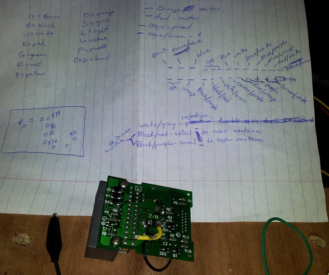
in my case i had for some reason lost continuty between various connection within the PCB so had to do some bypass, also had to fix the white flex cable from the switch itself to the pcb, it had broken off on one side. had to soder a few wires there too but not shown in the pics.
this is a tedious little job that requires alot of patience. hopefully with this bit of info it will be easier for you.
probably the same for rear passenger switches.
wires:
fat wires.
BLUE = motor
ORANGE = motor
BLACK = ground
BROWN/BLACK = positive
thin wires
BLACK/PURPLE = ground signal from driver door switch UP
BLACK/RED = ground signal from driver door switch DOWN
WHITE/BROWN = ignition switch
on the rear of the PCB there is no identification for the relay connections so i made this drawing while i was testing and figuring out what each connection was for the relays on the bottom left of the picture the drawing shows with circles the solder points. it might not make sense to look at it now but when you have the PCB in hand you will see the pattern. on their side is the relay connection #, refer to the first picture for what each connection should be wired too.
on the right side of the pic is the plug pinout with wire colors, i had to do it this way cause i needed to remember what each pin was for testing on a bench, i used a 12v PC powersupply to test.
in my case i had for some reason lost continuty between various connection within the PCB so had to do some bypass, also had to fix the white flex cable from the switch itself to the pcb, it had broken off on one side. had to soder a few wires there too but not shown in the pics.
this is a tedious little job that requires alot of patience. hopefully with this bit of info it will be easier for you.
Last edited by avioni; Jun 22, 2013 at 12:20 PM.


Thread
Thread Starter
Forum
Replies
Last Post
rentzoo
S-Type / S type R Supercharged V8 ( X200 )
11
Nov 10, 2015 04:56 PM
RaceDiagnostics
XK8 / XKR ( X100 )
20
Sep 13, 2015 02:22 AM
jagent
XJ6 & XJ12 Series I, II & III
8
Sep 12, 2015 09:10 AM
1964Daimler
MKI / MKII S type 240 340 & Daimler
0
Sep 9, 2015 11:28 AM
Currently Active Users Viewing This Thread: 1 (0 members and 1 guests)

