
Connection options, splicing electrical wires and how to do it right, and WRONG!

Thread Starter
|
Senior Member
Joined: Apr 2011
Posts: 152
Likes: 43
From: Pennsylvania, USA
I've been involved with a wiring nightmare.
The Previous Owner had no clue when it came to wiring a stereo in me mom's Honda Civic. For that matter, when it came to me it had no brake lights, or turn signals and the headlights are askew, so I guess the PO was what they call "electrically challenged".
I found wire splices made by just twisting bare wires together and using, of all things, duct tape to insulate them?!
 NO!
NO!
What really galled me is I found where he/she had tapped into a wire at a plug/socket by clipping the wire directly at the plastic, leaving no length with which to solder/crimp and return the harness the way it was from the factory.
I could go on ...
I've read where the XJ40s have come into the hands of those who have bought their first or second car.
In the hope there are those out there who would like to read a good page on how to do it the right way, please click on the following link:
Connection options, splicing wires and how to do it right, and WRONG!
Read it, and please apply it into your work ASAP.
You'll be doing yourself and the next owner of your Jaguar a favor and a service.
The Previous Owner had no clue when it came to wiring a stereo in me mom's Honda Civic. For that matter, when it came to me it had no brake lights, or turn signals and the headlights are askew, so I guess the PO was what they call "electrically challenged".
I found wire splices made by just twisting bare wires together and using, of all things, duct tape to insulate them?!
NO!What really galled me is I found where he/she had tapped into a wire at a plug/socket by clipping the wire directly at the plastic, leaving no length with which to solder/crimp and return the harness the way it was from the factory.
I could go on ...
I've read where the XJ40s have come into the hands of those who have bought their first or second car.
In the hope there are those out there who would like to read a good page on how to do it the right way, please click on the following link:
Connection options, splicing wires and how to do it right, and WRONG!
Read it, and please apply it into your work ASAP.
You'll be doing yourself and the next owner of your Jaguar a favor and a service.
Last edited by Trick Freestones; May 23, 2011 at 12:57 AM.
Veteran Member
Joined: Feb 2011
Posts: 9,733
Likes: 2,203
From: on-the-edge
The link given is a lightweight treatment of the subject with many omissions of fact. The most offensive one being the reference to "magic smoke".
A reader who believes that the referenced page is the ultimate in knowledge on the subject, or even an adequate treatment would be deluding themselves.
It is good enough ... maybe ... for youtube, twitter, facebook, et al where all the rest of the pure, unadulterated crap resides.
A reader who believes that the referenced page is the ultimate in knowledge on the subject, or even an adequate treatment would be deluding themselves.
It is good enough ... maybe ... for youtube, twitter, facebook, et al where all the rest of the pure, unadulterated crap resides.
Thread Starter
|
Senior Member
Joined: Apr 2011
Posts: 152
Likes: 43
From: Pennsylvania, USA
Surprised to read you were so disappointed that you felt compelled to give the link a "thumbs down".
I think the author included the term, "magic smoke", to lighten the subject.
My soldering pencil, when properly warm, will not only melt the solder when applied to the tip, but a quick "whiff of smoke" accompanies the melting. This tells me the pencil is hot enough and ready. When I now apply the pencil to my wires, the solder flows just right. If I don't wait for the "magic smoke" thing, my solder joints look starved.
There is an art to soldering.
Furthermore, if I didn't think the link was worthy, I wouldn't have posted it.
I've been trained and worked in the US Navy as an electrician's mate. I've worked in electronics assembly shops, too. So, I think I know at least a little bit about the subject.
I usually solder, but I found the discussion on crimping butt splices most enlightening.
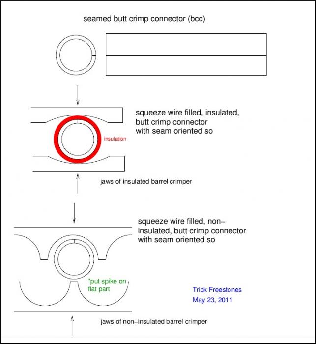
"Butt/Barrel Crimp Connectors"
Again, some shops swear by this method for its speed, while others enforce soldering only. There are insulated and non-insulated barrel (butt) connectors both being either seamed or seamless. The differences between seamed and seamless are mainly price (seamless cost more) and crimping methods. With seamed barrels there is a split running the length of the barrel. If crimping is done on both sides of the seam, the barrel will flatten out and not hold the wire tightly. When crimping is done on the seam and the opposite wall, the barrel tends to concave digging into the wire holding it more securely. With the more expensive seamless barrels you can crimp on it all around the barrel and it closes the same way. This saves time since you don't have to check the position of your crimp. Now with insulated and non-insulated barrels its more of a user preference. There are also different crimpers for both types. Insulated barrel crimpers look like a pair of pliers with 2 crescent shape groves on each side. While the non-insulated barrel crimpers have a groove and a spike on the other side. It is not recommended to use non-insulated crimpers on insulated barrels as it pierces the insulation leaving bare metal to cause problems.
Again, some shops swear by this method for its speed, while others enforce soldering only. There are insulated and non-insulated barrel (butt) connectors both being either seamed or seamless.
The differences between seamed and seamless are mainly price (seamless cost more) and crimping methods. With seamed barrels there is a split running the length of the barrel. If crimping is done on both sides of the seam, the barrel will flatten out and not hold the wire tightly. When crimping is done on the seam and the opposite wall, the barrel tends to concave digging into the wire holding it more securely. With the more expensive seamless barrels you can crimp on it all around the barrel and it closes the same way. This saves time since you don't have to check the position of your crimp. Now with insulated and non-insulated barrels its more of a user preference. There are also different crimpers for both types. Insulated barrel crimpers look like a pair of pliers with 2 crescent shape groves on each side. While the non-insulated barrel crimpers have a groove and a spike on the other side. It is not recommended to use non-insulated crimpers on insulated barrels as it pierces the insulation leaving bare metal to cause problems.
Veteran Member


Joined: Apr 2010
Posts: 7,657
Likes: 3,020
From: Arlington VA USA
IMO, soldering is best...however in the quest for ease and speed, these connectors are quick and quite reliable, though a bit pricey:
Posi-Lock(R) - The Best Connectors You'll Ever Use!
Posi-Lock(R) - The Best Connectors You'll Ever Use!

Senior Member
Joined: Nov 2010
Posts: 114
Likes: 7
From: Dominica
If you haven't got a soldering iron, twisting and taping is quite effective if properly done - to stop the tape coming loose (after a long time if it's good quality tape) it can be tied with thread.
Sounds crude, I know, been doing it for years and it works.
Sounds crude, I know, been doing it for years and it works.
Thread Starter
|
Senior Member
Joined: Apr 2011
Posts: 152
Likes: 43
From: Pennsylvania, USA
In order to repair the harness adapter from the factory Honda plug adapter to the Panasonic tuner/CD player plug, I decided to solder new wires to the PO amputated pins and undo the twisted wire & duct tape mess between the adapter to the plug. There I decided to give non-insulated butt crimp connectors (bcc) a go.
It may be my earlier non success with crimp connectors may very well have to do with that I didn't understand there was a seam and what to do about it.
For a non-insulated bcc, one can find the seam readily. I needed 11 of these for splicing the plug and socket wires.
For an insulated bcc, I had to peer down the insulation tube and look for the faint line. It's easier to probe for it with an X-acto bladed knife.
I placed a mark where this was on the outside insulation layer. I did the same on the other end. I then drew an axial line connecting the two marks, thus showing where the seam was when looking from the outside.
I also carefully marked around the circumference where the end of the metal connector was inside the plastic tube. I did the same on the other end. I used a Sharpie marking pen. I had to make four of these and used them on the four lines connecting the rear speakers to the factory harness.
These are the things to keep in mind when working with butt crimp connectors:
My previous crimp pliers could only do insulated bcc's, but I found a decent pair that could do both varieties at Lowe's for, I believe they were < $10.
Senior Member
Joined: Nov 2010
Posts: 114
Likes: 7
From: Dominica
None of us here are electronic technicians (I suppose), and I think all of that is rather confusing - can you be a bit less technical-sounding - I. for one haven't got a clue what you're talking about.
Trending Topics
Thread Starter
|
Senior Member
Joined: Apr 2011
Posts: 152
Likes: 43
From: Pennsylvania, USA
Hi jrwb,
It is a tough subject to get across but I'm glad to read you've taken an interest.
I use acronyms at times in my posts, but start off with the full word and introduce the shortcut there; e.g. butt crimp connectors (bcc).
If I use the proper word, you can usually "Google" it for more information.
I'll try to include more pictures and keep you in mind when writing in the future.
Some pics:
1. Vinyl Insulated Butt Splice Connectors (note: this particular one fits 22-18 gauge wire [AWG]). Note that for this one you can see where metal ends and where it's all plastic, but you still can't see where the seam is.

2. Non-Insulated Butt Splice Connector (this one for 16-14 gauge wire). The wire stop prevents each wire end (when inserting) from going beyond the middle of the splice. You can see where the seam is on the bottom.

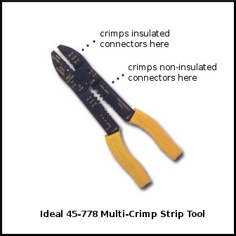
3. These are the crimpers I bought.
Ideal 45-778 Multi-Crimp Strip Tool (features: cuts wire, crimps insulated and non-insulated connectors, cuts small bolts, strips 10-22 AWG wire). Look carefully and you can see the "spike" where the non-insulated connectors are crimped. I read on the Internet, these are going for US$14.
It is a tough subject to get across but I'm glad to read you've taken an interest.
I use acronyms at times in my posts, but start off with the full word and introduce the shortcut there; e.g. butt crimp connectors (bcc).
If I use the proper word, you can usually "Google" it for more information.
I'll try to include more pictures and keep you in mind when writing in the future.
Some pics:
1. Vinyl Insulated Butt Splice Connectors (note: this particular one fits 22-18 gauge wire [AWG]). Note that for this one you can see where metal ends and where it's all plastic, but you still can't see where the seam is.
2. Non-Insulated Butt Splice Connector (this one for 16-14 gauge wire). The wire stop prevents each wire end (when inserting) from going beyond the middle of the splice. You can see where the seam is on the bottom.
3. These are the crimpers I bought.
Ideal 45-778 Multi-Crimp Strip Tool (features: cuts wire, crimps insulated and non-insulated connectors, cuts small bolts, strips 10-22 AWG wire). Look carefully and you can see the "spike" where the non-insulated connectors are crimped. I read on the Internet, these are going for US$14.
Thread Starter
|
Senior Member
Joined: Apr 2011
Posts: 152
Likes: 43
From: Pennsylvania, USA
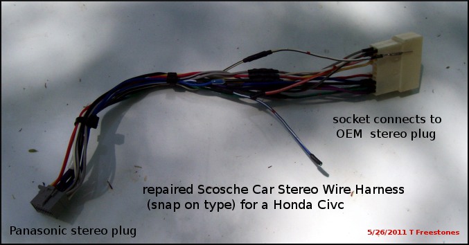
This is a blow-up of the middle where I spliced plug and socket wires together. I was supposed to stagger the splices, but I felt if I had problems with the crimps, then I would need as much wire as possible in order to make solder joints instead.
Also is a close-up of one of four wires I did not use. The ends had to be insulated some how. What I decided to do was to place the middle of a rectangular shaped piece of electrical tape over the end and fold it together so the glue surfaces would stick together when pressed. I repeated with another piece.
Then I gave it a CC twist in order for the edges to lay closer to the wire insulation. Next I cut a piece of 1/8" heat shrink tubing and slipped it over the electrical tape. After heating with a hot air gun, it made a nice tight fit.
Veteran Member
Joined: Jul 2009
Posts: 12,704
Likes: 1,236
From: Brittany France
Nice neat job you did there. Puts some of my youthful fire hazard twist and tape jobs to shame.
You might want to explain how the seam works in the connector when you crush with the crimpers and why the position in the crimper is important for rolling the connector around the wires rather than just flattening the connector, plus how to correctly action the crimp process, especially if the length of available wire is at the limit of being short.
Nothing worse than chopping straight through a wire and then not having enough left to make the join.
I know that you know what I mean, but a diagram or pic of the differences between correct crimp crush position and an incorrect position should help to make things clearer as to why position is important.
Try to show an internal image of a correctly and an incorrectly crushed connector.
Sounds pedantic, but can make all the difference, if a wire is slightly loose inside a connector, arcing, radio interference, strange blown fuses, erratic operation, etc.
Thread Starter
|
Senior Member
Joined: Apr 2011
Posts: 152
Likes: 43
From: Pennsylvania, USA
Thanks Richard.
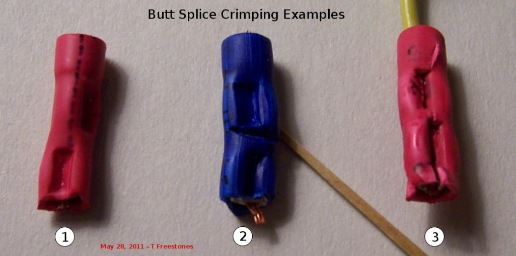
Here is a pic of three examples of crimps I removed from the harness before I restored it. I don't take credit for these - the previous installer did them.
If you imagine your self at the bottom end of each, trying to look through the connector
another pic forthcoming ...
Here is a pic of three examples of crimps I removed from the harness before I restored it. I don't take credit for these - the previous installer did them.
If you imagine your self at the bottom end of each, trying to look through the connector
- the seam of connector 1 is at the 12 o'clock position (yes, I have represented it with a dashed line drawn on the insulation)
- the seam of connector 2 is at the 9 o'clock position and
- the seam of connector 3 is at the 6 o'clock position. This is the proper position - opposite the spike of the crimp.
another pic forthcoming ...
Last edited by Trick Freestones; May 28, 2011 at 02:57 PM.
Thread Starter
|
Senior Member
Joined: Apr 2011
Posts: 152
Likes: 43
From: Pennsylvania, USA
Using a modeler's saw, I carefully cut and removed the insulation from above.
Here is a pic revealing the nature of the two bad crimps and the one desired which is on the far right (#3).
Arrows point to the seam for each crimp example. It is readily apparent that the quality of the crimp is dependent upon seam orientation with respect to crimp plier contact position.

Here is a pic revealing the nature of the two bad crimps and the one desired which is on the far right (#3).
Arrows point to the seam for each crimp example. It is readily apparent that the quality of the crimp is dependent upon seam orientation with respect to crimp plier contact position.

Member
Joined: May 2011
Posts: 36
Likes: 0
From: Seattle, Washington, USA
Trick...
Man, you do nice work. Very neat.
Thanks for taking the time with this thread. Some of the injector plugs on my XJ12 need to be replaced. The PO of my car had two parts cars and he let me grab the plug harness from one to use as replacements. Your thread will be a lot of help.
Thanks again
Man, you do nice work. Very neat.
Thanks for taking the time with this thread. Some of the injector plugs on my XJ12 need to be replaced. The PO of my car had two parts cars and he let me grab the plug harness from one to use as replacements. Your thread will be a lot of help.
Thanks again
Thread Starter
|
Senior Member
Joined: Apr 2011
Posts: 152
Likes: 43
From: Pennsylvania, USA
Robert,
Thanks for the compliment. I'm glad to read you found it useful, too.
~~~~
I did some soldering on this harness, also.
This took place at the snap-on connector where the harness joined the OEM stereo plug. As I said before, the PO clipped 10 of the pin wires almost at the plastic shell in order to save him the trouble of doing any insulation work.
I guess it never occurred to him that someday, he might want to "put it back the way it was".
Thread Starter
|
Senior Member
Joined: Apr 2011
Posts: 152
Likes: 43
From: Pennsylvania, USA
I found I was able to remove each of the connector pins by gently inserting a partially straightened paper clip into the maw of the socket. Then a slight push on the paper clip and a gentle tug on the wire remnant, removed the socket pin.

I removed what insulation I could from the pin wire and duplicated that amount on the wire to be attached. I then found a larger diameter (smaller gauge no.) wire, removed a length of insulation and clipped a single strand from it.
I overlapped the two wire ends I wished to solder and wrapped the joint with the single strand. I then held this in a "third hand" vise and soldered the joint. Sinc the pin end was free of the socket, I was still able to slide a piece of Heat shrink tubing now and complete the joint.
It took a bit of time to finish this harness repair.

Thread
Thread Starter
Forum
Replies
Last Post
Currently Active Users Viewing This Thread: 1 (0 members and 1 guests)