
Lamp Module Repairs

Thread Starter
|
Junior Member
Joined: Jul 2012
Posts: 17
Likes: 8
From: New Zealand
Hey chaps, figured it wouldnt hurt to post this here in case it can benefit any other users.
So on my 87 XJ40, I recently swapped to round headlights from the bricks. After fitting it all up, i went for a drive and everything was sweet. However after a couple of days, i began to get false lamp failure warnings.
The intermittent warnings progressed to a constant one whenever any lights were on. Anyone with a digital dash will know how annoying this is on a 6 hour night drive! Even the indicator ticker was speeding up which ruined the calm flow of my morning commute.
Always try the simple stuff first, so i checked to make sure all bulbs were functioning and of the correct wattage and cleaned up the ground wires. At this point, from what ive read - the majority of people will replace the lamp modules. But, I live in New Zealand and although the cars are worthless here - people somehow feel justified charging moonbeams for the parts. I do import a box of parts from the UK every couple months but didnt want to wait or waste money so decided to explore the repair option.
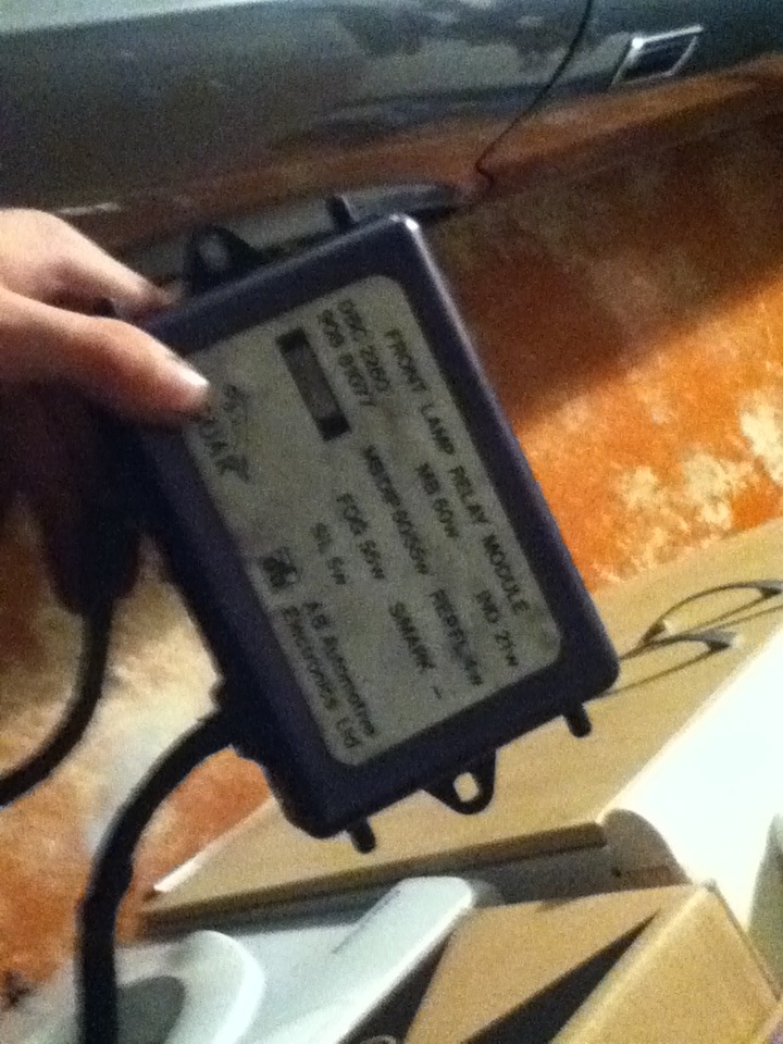
I dont have much of an electrical backround but figured id give it a try anyways and cracked into the modules. The back cover is removed by straightening out some bent bits of metal and then prying off.
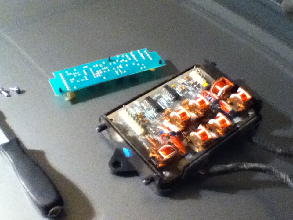
Inside, there are 2 distinct boards which can be seperated. The lower board contains all manner of beefy resistors and relays. To my untrained eye - there wasnt much silicon down there so i figured the logic board for the lamp failure monitoring was the top one. It seemed smarter in my mind from a design perspective to keep the 2 functions seperate.
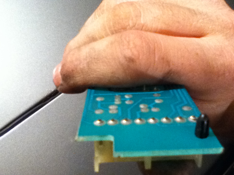
Immediately found some dry solder joints on the connectors between the top board and the big bottom one. This also makes sense to me since these joints would have been under the most mechanical pressure when installed. They also probably suffer a bit from stress when the pins inside the connectors expand and contract with the module warming/cooling.
Seen in the photo - with light pressure applied, the far left and far right joints split easily. Not seen - one or two of the center joints was also dodgy and required much closer examination to spot.
Corrected that and bingo - everything is working as it should. Half an hour with a soldering iron, some high flux solder and a few basic tools and thats another problem sorted!
Both modules had failed in the exact same manner, so rinse repeat for the drivers side module.
Next mission is to sort out the coolant level sensor which throws up "LOW COOLANT LEVEL" messages on the same bright screen. It irritates me far less frequently, so its not as big a priority. The float switch doesnt float as well as it used to, so when the coolant gets hot - it sinks and trips the warning. I think i'll just stick some low density foam to it instead of paying 30 quid for a new one.
Moral of the story: These days, your average automotive control module is a big chunk of silicon chips relying on CANbus protocols and waveform signals. This puts them well outside the reach of a backyard mechanic and even most workshops.
The XJ40 is from a bygone era where all of the computer stuff communicated in simple analogue ways. Everything was made from big easy to identify componentry and so is far easier for the electrical novice to repair.
So on my 87 XJ40, I recently swapped to round headlights from the bricks. After fitting it all up, i went for a drive and everything was sweet. However after a couple of days, i began to get false lamp failure warnings.
The intermittent warnings progressed to a constant one whenever any lights were on. Anyone with a digital dash will know how annoying this is on a 6 hour night drive! Even the indicator ticker was speeding up which ruined the calm flow of my morning commute.
Always try the simple stuff first, so i checked to make sure all bulbs were functioning and of the correct wattage and cleaned up the ground wires. At this point, from what ive read - the majority of people will replace the lamp modules. But, I live in New Zealand and although the cars are worthless here - people somehow feel justified charging moonbeams for the parts. I do import a box of parts from the UK every couple months but didnt want to wait or waste money so decided to explore the repair option.
I dont have much of an electrical backround but figured id give it a try anyways and cracked into the modules. The back cover is removed by straightening out some bent bits of metal and then prying off.
Inside, there are 2 distinct boards which can be seperated. The lower board contains all manner of beefy resistors and relays. To my untrained eye - there wasnt much silicon down there so i figured the logic board for the lamp failure monitoring was the top one. It seemed smarter in my mind from a design perspective to keep the 2 functions seperate.
Immediately found some dry solder joints on the connectors between the top board and the big bottom one. This also makes sense to me since these joints would have been under the most mechanical pressure when installed. They also probably suffer a bit from stress when the pins inside the connectors expand and contract with the module warming/cooling.
Seen in the photo - with light pressure applied, the far left and far right joints split easily. Not seen - one or two of the center joints was also dodgy and required much closer examination to spot.
Corrected that and bingo - everything is working as it should. Half an hour with a soldering iron, some high flux solder and a few basic tools and thats another problem sorted!
Both modules had failed in the exact same manner, so rinse repeat for the drivers side module.
Next mission is to sort out the coolant level sensor which throws up "LOW COOLANT LEVEL" messages on the same bright screen. It irritates me far less frequently, so its not as big a priority. The float switch doesnt float as well as it used to, so when the coolant gets hot - it sinks and trips the warning. I think i'll just stick some low density foam to it instead of paying 30 quid for a new one.
Moral of the story: These days, your average automotive control module is a big chunk of silicon chips relying on CANbus protocols and waveform signals. This puts them well outside the reach of a backyard mechanic and even most workshops.
The XJ40 is from a bygone era where all of the computer stuff communicated in simple analogue ways. Everything was made from big easy to identify componentry and so is far easier for the electrical novice to repair.


Thread Starter
|
Junior Member
Joined: Jul 2012
Posts: 17
Likes: 8
From: New Zealand
I figured it would be the 2 front modules as the system worked fine with the old headlights and the old modules.
The lamp failure warning did come back once briefly for 5 seconds out of 3 hours driving....so im not 100% sold but its a vast improvement from having it on constantly.
The lamp failure warning did come back once briefly for 5 seconds out of 3 hours driving....so im not 100% sold but its a vast improvement from having it on constantly.

Thread
Thread Starter
Forum
Replies
Last Post
trosty
XJ XJ6 / XJ8 / XJR ( X350 & X358 )
26
Dec 18, 2022 06:40 PM
John Fox
XK8 / XKR ( X100 )
2
Sep 19, 2015 07:56 PM
Currently Active Users Viewing This Thread: 1 (0 members and 1 guests)