When you click on links to various merchants on this site and make a purchase, this can result in this site earning a commission. Affiliate programs and affiliations include, but are not limited to, the eBay Partner Network.
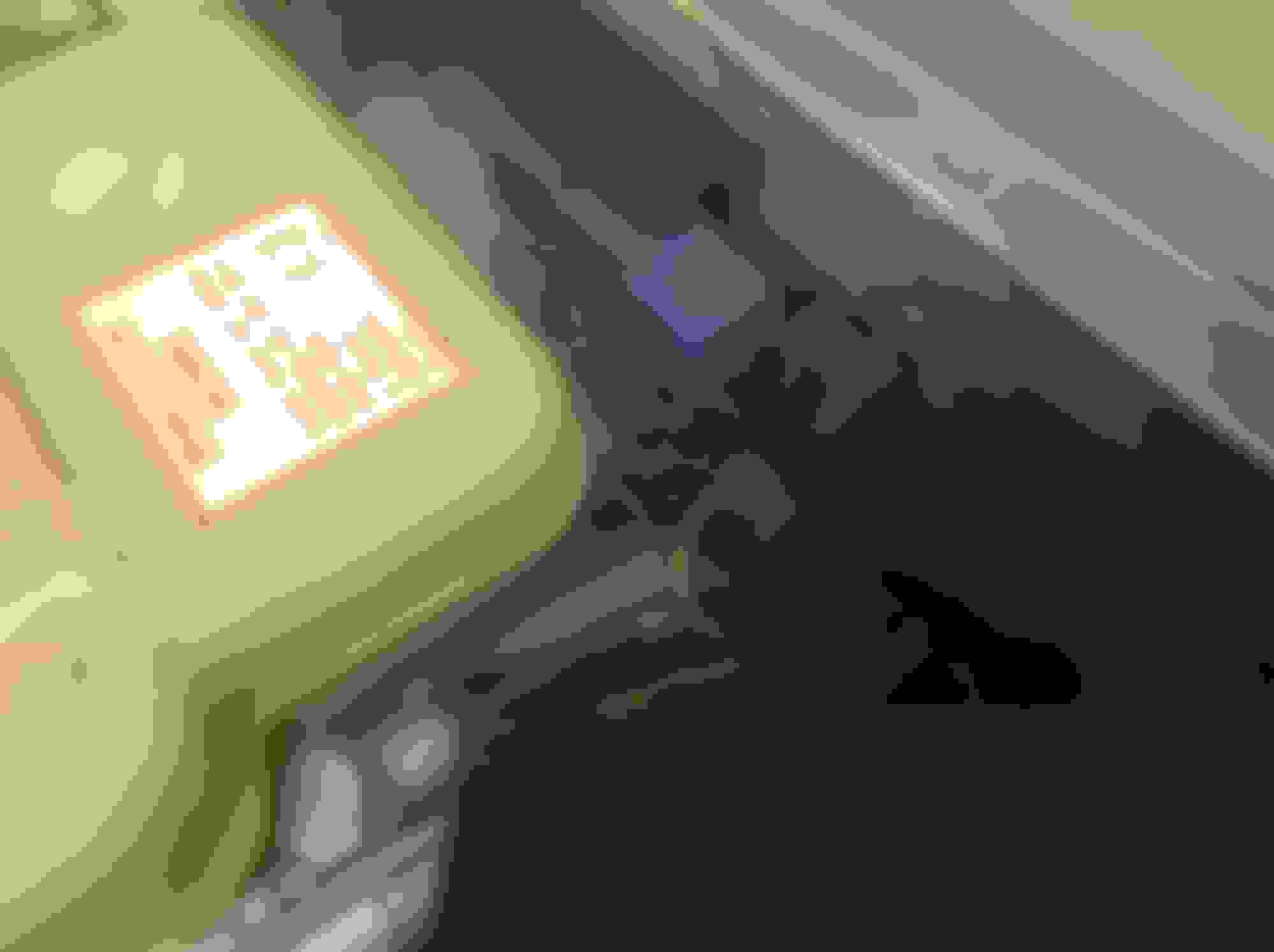
Looking for a bit of advice on a parasitic voltage drop on my 6.0 coupe. I'm no auto electrician unfortunately but since I got this vehicle a couple of months ago, there has been a draw of about 0.4amp from the battery whilst the vehicle is parked up inside and locked ( I put in a brand new battery - since found there was nothing wrong with the old one) I've looked at various methods of tracing a power leak on U-tube and learnt how to measure at the battery if there is a parasitic draw to start with. Whilst having a check around the areas of the fuse locations before starting to check for millivolt drop across each fused circuit, I took the cover off the RHS underbonnet relay bank and noticed the black relay in the picture was actually warm to the touch ( this being with the car having sat for several days without being started) I am wondering if this may be the source of the problem. It also looks like someone in the past has done a bit of amateur wiring around this relay and a couple of wires are severed and there is resistor or something attached that I do not recognise (second photo) I'd be really grateful if somebody out there knew what function this relay served and what the function of the resistor may have been for?
Black relay on RHS is warm to touch Unknown object?
the diode is located directly beneath the black relay already pictured. upon searching,I believe the relay may be the starter relay. the diode has at some time been disconnected by cutting through the red wire -so it isn't actually wired in to the circuit anymore. the black relay pictured doesn't look original to me and if so, may be differently configured, making it necessary to alter the wiring and take out the diode (this is all theory by the way! as i'm no expert when it comes to the electrics) but I do have an eye for detail and the fact that this relay is warm to the touch makes me think that this could be part of the current draw i'm experiencing.
I may try and source the correct relay and then take the car to an auto electrician to refit and rewire the diode (whatever its use is - it must serve some purpose i guess)
Diode rfd2 is shown as being around that location connected to start relay and associated with security system and start inhibit switch (black/green wires)
if you have a slow draw it may well be security system, maybe that's the connection.
The Jaguar Electrical Guide has ALL the relay locations and positions in the FRONT MATTER section.
Working on the electrical system without a guide is going to take a Loooong time figuring what-goes-where.
Ok, so thanks to this forum I have sourced a 1995 wiring diagram and identified the "mystery" relay as being the starter relay ( has been replaced at some point)
the RFD2 diode is present but the red wire from it that links into contact 87 (I think - it's difficult to see) of the starter relay has been cut and a new wire has been attached to the relay end of the cut wire and connected to Earth via screw on the bulkhead. It would appear therefore, that the RFD2 diode is no longer attached to anything.
So my question now is for someone with more knowledge than me as to the function of the diode and why should someone seek to do this? Could this result in the power draw I'm seeing in the car? The car starts and drives ok with this arrangement but it's obviously not as it should be.
Mine is a 4.0 but the circuit is the same showing the diode.
The diode simply ensures the ground-leg to the relay is not back fed by any of the other computers or loads grounds. Diodes arrows always point to the ground point/source, and in this circuit the source is after the security module. For a successful start, the ground path has to be completed first. Security system unlocked, transmission lever in Neutral or Park. The same ground is used by the Conv top and the engine management. You can see in the diagram.
The resistor in the relay is a voltage suppression resister much like a diode is sometimes used. Some relays use resisters and some use diodes. The ones using resistors are more robust and can take higher spikes saving the components attached to it. It's possible that the internal resistance of the resistor has been reduced over time however, the the relay wouldn't be warm to the touch if voltage weren't there in the first place. Why is it there? This is the part that bothers me. The only time control voltage should be introduced to the relay is during start. Once the ground is available due to the those conditions being met, the 12 volts brought by the ignition switch to start should be the only time the relay is activated. We need to know why power is at the relay when there should not be any regardless of the ground condition on the other side of the coil.
Time to probe the 86 receptacle at the relay base ignition off.
Last edited by carsnplanes; Dec 29, 2018 at 08:11 AM.
Thanks for the great advice. I have probed contact 86 on the starter relay and it is indeed live with the ignition off and no key present although vehicle is unlocked. There is a brown, fairly heavy cable into this contact 86 that is protected in a corrugated plastic sheath but I can't see where this runs to.. I take it though that it should not be live with the ignition off? I have left the relay out of its socket receptacle for the moment as it worries me that a fault is present somewhere.
Thanks for the great advice. I have probed contact 86 on the starter relay and it is indeed live with the ignition off and no key present although vehicle is unlocked. There is a brown, fairly heavy cable into this contact 86 that is protected in a corrugated plastic sheath but I can't see where this runs to.. I take it though that it should not be live with the ignition off? I have left the relay out of its socket receptacle for the moment as it worries me that a fault is present somewhere.
Correct. Should not be live with ignition off. Keep going back from the relay to the ign switch. Also, check the other ign switched power distribution points (red). If the start relay is live, then if all is equal, the other distribution points should be live too if the switch is leaking when off.
Below diagram shows three possible paths of the switch, each going to distribution points and eventually fuses and associated components. How much voltage were you measuring at the point 86 on the relay base?
You can see "Box" 1 is battery power going to the ign switch so it's HOT 12volts in to the switch. The out of the switch or "triangle 3" is switched power, or in this case during the start. That delivers 12 V to the relay and if all grounds are good, the relay is activated.
Last edited by carsnplanes; Dec 29, 2018 at 09:44 AM.
Right, I have just checked the rest of the relays in the engine bay and all four on the RHS including the starter read a full 13volts at contact 86 and also the first four out of six relays on the LHS read 13 volts at contact 86 and so does the 30 amp fuse - all this with the ignition off and no key in the ignition.
I am thinking this has to be a faulty ignition switch? But I haven't yet got round to dismantling the steering column shroud etc to get to it. If it proves to be the switch, do you know if it can be replaced without changing the lock barrel etc?
yes, should be a snap in electrical portion on the rear of the lock cylinder as in most cars. It will have a connector pigtail where it will plug into the car side of the wring. The key and tumbler side should stay intact and the back end has a rotating shaft, probably square end that fits on the inside of the switch. The switch contains all the contacts internally as well as the spring loaded start position.
I would first locate the connectors, unplug them and do a final electrical check as you rotate the key from off to start position and observing the 12 V output and when in off.
I'm really most obliiged to you taking the time to reply to my questions - I now feel as though I'm heading in the right direction with this and hopefully I can get it sorted out. Thanks for passing on your knowledge to an enthusiastic amateur! I will post again when I finally resolve the issue!
I'm really most obliiged to you taking the time to reply to my questions - I now feel as though I'm heading in the right direction with this and hopefully I can get it sorted out. Thanks for passing on your knowledge to an enthusiastic amateur! I will post again when I finally resolve the issue!
Confirm also that when you remove the relay and you go to "start" position with key, that you get the 12V as you should at 86. If what you're saying is correct that you have 12V at 86, then 12Volts never goes away from 86 as it should after you've completed your start (back to ignition only position). If there was 12Volts at pin 86 all the time and you had all the ground conditions as you should, then the start relay should always be energized enough to keep the starter spinning. Why is that not happening? Did they do something to the wiring to switch the ground rather than the 12 Volts knowing it was there all the time with a bad switch? Perhaps that is why the wiring looks messed with.
Yes, I see what you mean. When I put the key in and turn it to the pos 3 start, there is still full 12.8 volts measuring from position 86 on the starter relay. I can't quite fathom it out. Unless the wire being cut just after the RFD2 diode has made the difference?
Yes, I see what you mean. When I put the key in and turn it to the pos 3 start, there is still full 12.8 volts measuring from position 86 on the starter relay. I can't quite fathom it out. Unless the wire being cut just after the RFD2 diode has made the difference?
The diode is on the ground side of the relay coil, so no power should be feeding 86 from there. Best thing to do is to remove the bottom column cover and find the switch connectors and unplug them. That "should" remove the power path from the ign switch to the relay base and should have no power on 86 as a result. If there is, then somebody added or spliced power into the wire going to 86. Not sure why they would do that but who knows.
Do wire checks on each of the relay pins on the base and confirm they are all going to where they are supposed to . I have a 4.0 and my wiring diagram may be slightly different from your V12 wiring page,so compare diagrams. I think they're the same as far as start and ignition is concerned. Maybe different on the ignition because of the V12 coils, distributor etc. I have a computer ECU and coil packs for the spark plugs but that really shouldn't matter for the start.
??????
Brown wire to 86. Brown wire should be live since it is unswitched battery voltage BUT it should NOT be attached to 86, should be 30.
Is it possible somebody has messed with the position of the wires/terminations within the relay plugs. Confirm orientation of correct wires to relays.
??????
Brown wire to 86. Brown wire should be live since it is unswitched battery voltage BUT it should NOT be attached to 86, should be 30.
Is it possible somebody has messed with the position of the wires/terminations within the relay plugs. Confirm orientation of correct wires to relays.
On my diagram, brown (N) is hot comimg from hot batt to the ign switch. Then start position out to pin 86, (coil 12v side) is one of the white wires. In either case, start relay should only have start voltage at position 3 spring loaded. Ground is waiting at the neg side of the coil.
I've just discovered that the replacement relay I has differently configured pins compared to the original Jaguar units.
The Jaguar relay position of pin 30 = 86 in the replacement relay; 87 = 30 ; 85 = 87 and 86 = 85
Someone smarter than me might be able to work out how the car managed to start but not continually crank the starter whilst in this configuration - I still don't know why someone took a wire directly to earth from the RFD2 wire (Jaguar relay position 85) unless that facilitated the replacement relay to function.
It has taken me all day to get this far with thr invaluable help of you guys. Tomorrow I shall source a replacement Jaguar relay and remake the original RFD2 connection and see how that goes. fingers crossed!
I've just discovered that the replacement relay I has differently configured pins compared to the original Jaguar units.
The Jaguar relay position of pin 30 = 86 in the replacement relay; 87 = 30 ; 85 = 87 and 86 = 85
Someone smarter than me might be able to work out how the car managed to start but not continually crank the starter whilst in this configuration - I still don't know why someone took a wire directly to earth from the RFD2 wire (Jaguar relay position 85) unless that facilitated the replacement relay to function.
It has taken me all day to get this far with thr invaluable help of you guys. Tomorrow I shall source a replacement Jaguar relay and remake the original RFD2 connection and see how that goes. fingers crossed!t