More 'shielded wire' questions...but not the one you're thinking of!
#21
Join Date: Nov 2013
Location: Inverell, NSW, Australia
Posts: 3,014
Received 1,410 Likes
on
876 Posts
Hey Doug,
Tried it; doesn't work . . . so, I use cotton buds!
Great question . . . and I don't know and can't find among Jaguar tech resources. We do know that our systems interpret all these "potentiometer" type sensors via A/D converters. I can remember early days of only 8 or 16 steps across full scale in many fields of electronics . . . somewhat like the good old "grey scale" . . . but these days, 16million step A/D converters are commonplace.
This fits with comment that later Jaguars need more precise analogue voltage settings . . . but still leaves us wondering about TPS in XJ's.
Cheers and best wishes,

Ken
Great question . . . and I don't know and can't find among Jaguar tech resources. We do know that our systems interpret all these "potentiometer" type sensors via A/D converters. I can remember early days of only 8 or 16 steps across full scale in many fields of electronics . . . somewhat like the good old "grey scale" . . . but these days, 16million step A/D converters are commonplace.
This fits with comment that later Jaguars need more precise analogue voltage settings . . . but still leaves us wondering about TPS in XJ's.
Cheers and best wishes,
Ken
#22
Join Date: Mar 2008
Location: Pacific Northwest USA
Posts: 24,743
Received 10,757 Likes
on
7,101 Posts
Since the original TPS was dead I installed the Mustang TPS that I had bought ages ago 'just in case'. Not unexpectedly it doesn't allow voltage as low as .32v so nothing has been proven or disproven with respect to my fixed feedback mystery. However, it does deliver 4.55v at WOT....which seems like a far less important thing.
I bought another Mustang TPS to open up and experiment with in an effort to increase rotational travel to allow .32v. As-is, the voltage is .44v which doesn't seem to cause anything palpably bad.
The car runs and drive perfectly well so I'm shelving this project for a bit while I move on to finishing the conversion and refurbishment process, which is down to a wheel alignment, new mufflers, and an A/C recharge.
I'll come back to the small stuff later.
Oh......
In a rare moment of cleverness I soldered two 'test' pigtails into the TPS harness so that checking voltage in the future will be easier.
Cheers
DD
The following users liked this post:
cat_as_trophy (04-28-2017)
#23
The following users liked this post:
Doug (04-28-2017)
#24
Join Date: Nov 2013
Location: Inverell, NSW, Australia
Posts: 3,014
Received 1,410 Likes
on
876 Posts
The following users liked this post:
Doug (04-28-2017)
#25
This thread appears to have moved from O2 grounding to TPS related trouble shooting but according to 81 - 88 XJS Engine Performance S58.pdf the ECU and injector grounds, all ground to the chassis and the shielding for the O2 sensors and to pin 23 ground to the engine.
This is obviously significant at least on my 1983 XJS as the feedback according to my air/fuel gauges when shielding is grounded to the engine is improper, does not cycle as it should for both left and right banks but when the shielding is grounded to the chassis or directly to the battery the left bank performs perfectly with the right bank looking like it is in open loop.
This malady is the same for two different ECUs and two different power resistors packs. Cannot understand after days of trouble shooting everything as to the difference in the two banks.
Also to further confuse the issue before the alternator begins charging both banks operate perfectly until charge begins and then left bank continues to operate properly while right bank appears to go into open loop. Have thought there must be a floating ground problem somewhere south of the ECU but have been unable to locate such.
#26
Join Date: Mar 2008
Location: Pacific Northwest USA
Posts: 24,743
Received 10,757 Likes
on
7,101 Posts
Only because of the (apparent) necessity for the ECU to see .32v from the TPS before allowing the feedback monitor system to function
but according to 81 - 88 XJS Engine Performance S58.pdf the ECU and injector grounds, all ground to the chassis and the shielding for the O2 sensors and to pin 23 ground to the engine.
Right.
The only note being that the ground for the O2 sensor heaters is a 'chassis' ground....but your '83 will not have the heated sensors unless it has been upgraded
This is obviously significant at least on my 1983 XJS as the feedback according to my air/fuel gauges when shielding is grounded to the engine is improper, does not cycle as it should for both left and right banks but when the shielding is grounded to the chassis or directly to the battery the left bank performs perfectly with the right bank looking like it is in open loop.
This malady is the same for two different ECUs and two different power resistors packs. Cannot understand after days of trouble shooting everything as to the difference in the two banks.
Also to further confuse the issue before the alternator begins charging both banks operate perfectly until charge begins and then left bank continues to operate properly while right bank appears to go into open loop. Have thought there must be a floating ground problem somewhere south of the ECU but have been unable to locate such.
I wonder if your RH bank exhaust pipe...where the O2 sensor screws in... is not well grounded? No ground = inoperative O2 sensor. Something to check.
FWIW, as part of my conversion project, and just on general principles, I ran a redundant ground cable from the engine block to the same chassis ground point shared by the main battery ground and all the other F. I. grounds. Mine is a Series III sedan, though, so the lay of the land is a bit different.
I added a ground to the ECU case as well, just on GP. Not sure if it does anything useful.
Cheers
DD
#27
Actually the feedback system works just fine with the TPS unplugged, in fact it seems totally unnecessary as the vacuum line to the ECU seems to handle throttle changes very well on my car but that may be because it, the upgraded fuel pump regulator and my vacuum gauges are the only things using vacuum on my car as I removed all the air valves on the car years ago.
I have one voltage regulator that does not activate until at least 3500 rpms for some inane reason so it is possible to drive down the road with the feedback system working perfectly just as long as under 3500 rpms but just as soon as the alternator begins charging the right bank stops cycling. Thanks to that regulator I know everything in the system works as long as it is not charging, therefore, I think the logical approach is to determine what happens to change that for the right bank only.
To provide some background, I have relocated all ignition and fuel injection components in this car including the ECU, main and fuel relays and power resistors to the cabin with a serious shortening of the harness, so tracing wiring and confirming continuity is quite easy. The ECU now resides where the glove compartment was for example. The harness to the boot now consists of a single wire to the fuel pump.
BTW the relocation of the ECU, power resistors and main and fuel relays was done after I started having this problem with O2 feedback and the ignition system components were moved many years ago before any problem presented.
I appreciate your input, thank you.
ciao,
Frank Young
#28
Join Date: Mar 2008
Location: Pacific Northwest USA
Posts: 24,743
Received 10,757 Likes
on
7,101 Posts
Ahhh, good to know, thanks
in fact it seems totally unnecessary as the vacuum line to the ECU seems to handle throttle changes very well on my car but that may be because it, the upgraded fuel pump regulator and my vacuum gauges are the only things using vacuum on my car as I removed all the air valves on the car years ago.
I'm not entirely surprised. But I would've been surprised a couple weeks ago.
I discovered my TPS was dead in the course of general checking of V12 basics. The car was driving very nicely with the TPS sitting on a fixed voltage. Only one time did I notice a glitch....on moderately fast throttle opening on a not-fully-warmed-up engine. This reinforces the TPS function of commanding a squirt of fuel to catch up with incoming air....like an accelerator pump on a carburetor.
I'm not entirely clear about TPS function during steady-state situations. IOW, if you're driving down the highway at a constant throttle opening, is the TPS playing much of a role in overall mixture control? I'm thinking "no" but Jaguar literature is a bit vague and contradictory on this.
I have one voltage regulator that does not activate until at least 3500 rpms for some inane reason so it is possible to drive down the road with the feedback system working perfectly just as long as under 3500 rpms but just as soon as the alternator begins charging the right bank stops cycling. Thanks to that regulator I know everything in the system works as long as it is not charging, therefore, I think the logical approach is to determine what happens to change that for the right bank only.
To provide some background, I have relocated all ignition and fuel injection components in this car including the ECU, main and fuel relays and power resistors to the cabin with a serious shortening of the harness, so tracing wiring and confirming continuity is quite easy. The ECU now resides where the glove compartment was for example. The harness to the boot now consists of a single wire to the fuel pump.
BTW the relocation of the ECU, power resistors and main and fuel relays was done after I started having this problem with O2 feedback and the ignition system components were moved many years ago before any problem presented.
I appreciate your input, thank you.
You're welcome and keep us posted on your findings
Cheers
DD
#29
Doug I wanted to let you know that I added an extra ground cable to the engine even though the original braided cable appeared to be intact and voila, problem solved. I suspect this could be the source of many O2 feedback problems others experience.
My experience suggests anyone driving one of these cars should have air/fuel ratio gauges installed for both banks as I would never even have known how lean this problem was making my right bank run if I did not have such gauges installed.
BTW after adding that cable I had to hook the TPS back up otherwise it would die when throttle was increased so whenever everything is as it should be the TPS is absolutely required to drive the car even if the feedback system in regard to O2 sensors is not dependent on it.
Thanks for your suggestions.
Regards,
Frank Young
The following users liked this post:
Doug (05-02-2017)
#30
According the documentation I was reading the other day the TPS is only used for acceleration enrichment. It is NOT used for load.
Grounding is a difficult subject and one I have had considerable experience with. What works for one may not work for another due to so may variable factors. One of the worst to fix is noise induced on the ground plane. This can be signal noise, say from ignition and plays havoc with ECU signals, the other is thermal noise caused by different materials, as these metals heat they produce a voltage and current flow in the ground circuit, thermal noise is usually in microvolts but with corrosion on metal surfaces could be as high as a few volts.
One fix that is universal and for the most part has resolved grounding issues I have fault found is STAR grounding. This is where ALL grounds come back to a single point a bit difficult in a vehicle but multiple stars work as long as the ground between is low resistance.
The following 2 users liked this post by warrjon:
cat_as_trophy (05-04-2017),
Doug (05-02-2017)
#31
I totally agree the TPS is irrelevant in this discussion. I also agree the problem from the outset in my situation has been one of grounding, however I do not agree all grounds should originate from a single point. If that was the case Jaguar would not have specified the grounding of the shielding for the O2 sensors going to pin 23 should be to the engine as there is a definite difference between grounding the shielding to the same location as the other ECU grounds at the chassis and grounding to the engine. I think the difference is that when the alternator which is grounded to the engine begins charging it changes the resistance in the ground at the engine where the O2 shielding is properly grounded which does not happen at the chassis ground. This is just my opinion based on my analysis of my problem and may not hold true universally although I seriously think it does.
Also there should be no uncertainly as to grounding or possible interference from the ignition in a properly grounded braided copper shielding of the O2 sensors. That at least is not a question of variables.
Also there should be no uncertainly as to grounding or possible interference from the ignition in a properly grounded braided copper shielding of the O2 sensors. That at least is not a question of variables.
The following users liked this post:
Doug (05-02-2017)
#32

Temperature, vacuum, oil pressure and air/fuel ratio gauges and relocated ECU in cabin along with main and fuel relays, power resistors and external voltage regulator
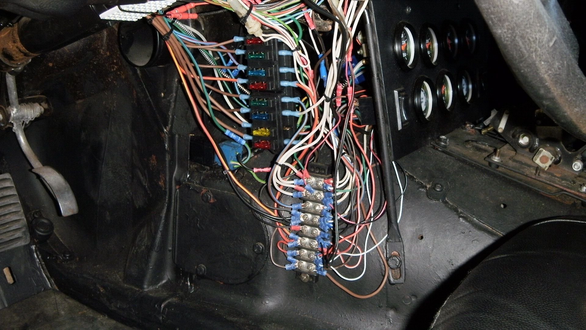
Total elimination of existing fuse panels and relays except main, fuel pump, headlights and cooling fans with 18" electric fan replacing original belt driven fan so now two electric fans
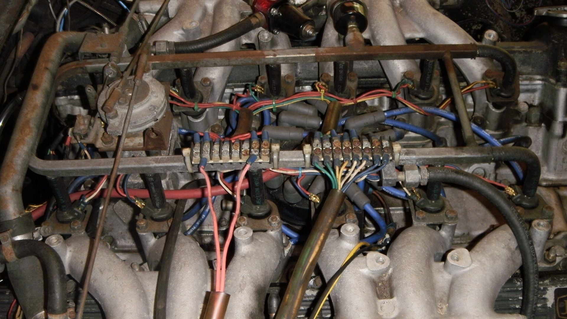
DIY fuel injection harness about $30 about 8 years ago, on top of engine, not in valley to prevent frying of wiring
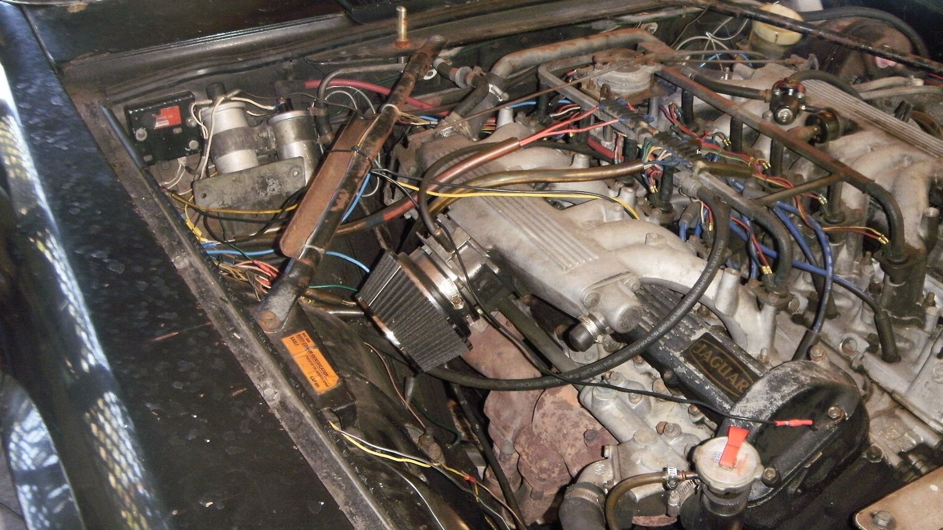
Relocated ignition components to avoid high heat areas
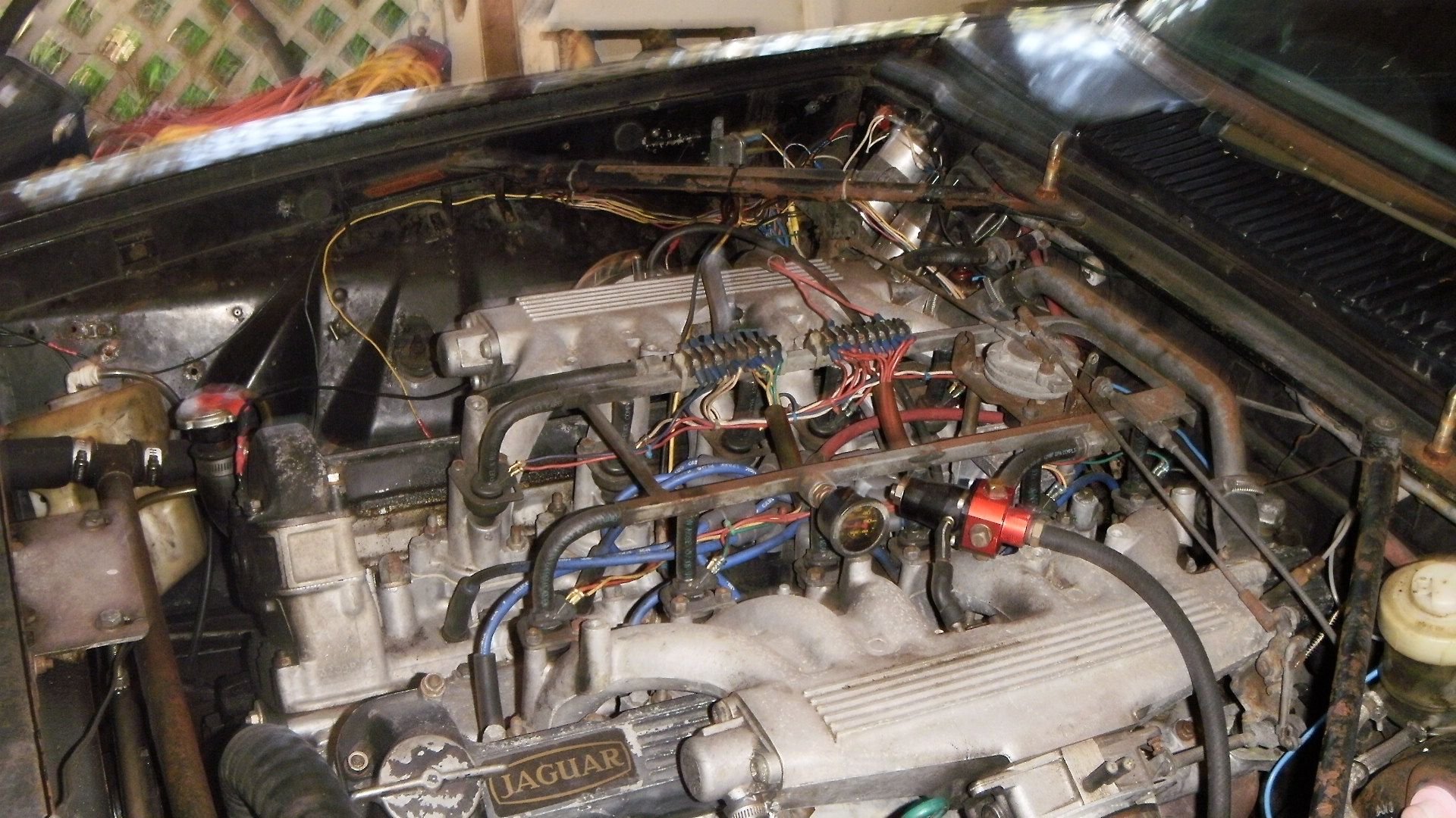
Extremely modified engine bay, check out the room, can change plugs in matter of minutes, not hours
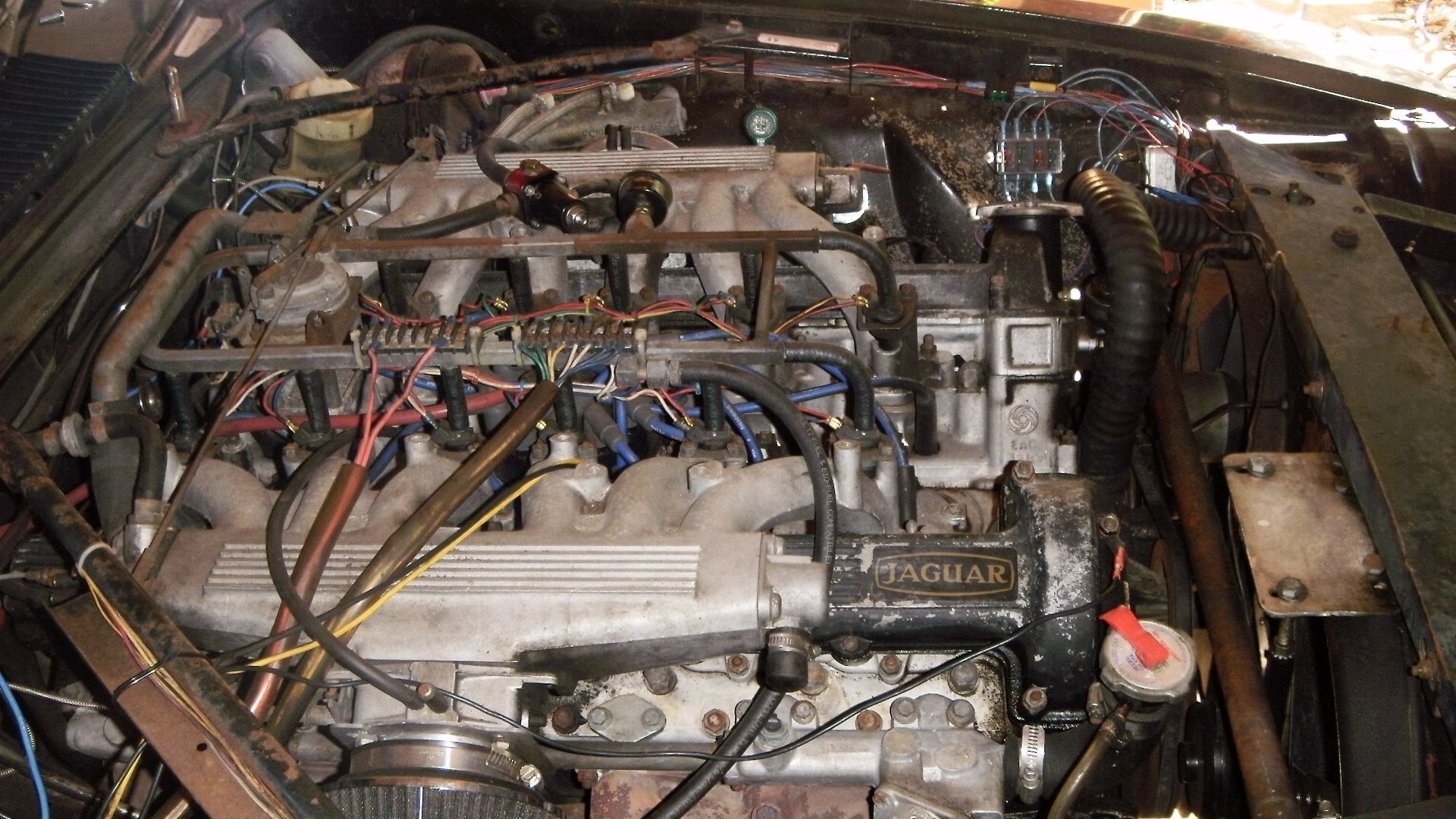
Redirected cooling system utilizing entire radiator for both banks
#33
If that was the case Jaguar would not have specified the grounding of the shielding for the O2 sensors going to pin 23 should be to the engine as there is a definite difference between grounding the shielding to the same location as the other ECU grounds at the chassis and grounding to the engine. I think the difference is that when the alternator which is grounded to the engine begins charging it changes the resistance in the ground at the engine where the O2 shielding is properly grounded which does not happen at the chassis ground. This is just my opinion based on my analysis of my problem and may not hold true universally although I seriously think it does.
Also there should be no uncertainly as to grounding or possible interference from the ignition in a properly grounded braided copper shielding of the O2 sensors. That at least is not a question of variables.
Also there should be no uncertainly as to grounding or possible interference from the ignition in a properly grounded braided copper shielding of the O2 sensors. That at least is not a question of variables.
Grounding a shield should be done at ONE end ONLY and it is not actually a ground but a GUARD, this is how ALL aircraft are wired. If you ground the shield at both ends and there is a potential difference between the 2 grounds, this will cause a voltage drop and current will flow in the shield, this can be DC not so bad but AC can wreak havoc.
Jaguar got it wrong grounding the O2 sensors at both ends, look at any new car and the O2 sensor shield is connect at the ECU ONLY, this is more critical with wide band O2 sensors than narrow band as these have a wider tolerance for rich and lean.
The following users liked this post:
Doug (05-02-2017)
#34
Again, there is definitely a difference in the ground at the engine other than at the chassis and I believe, based on my experience that is due to the alternator being grounded at the engine and change occurring in the engine ground when the alternator is charging.
The copper shielding of the two O2 sensors is connected to a ground wire just before it enters the ECU which is grounded to the engine with the shielding connecting to pin 23 in the ECU grounding that connection so that is absolutely a ground.
I also do not understand why you think it is not a ground nor where you came up with the idea of the shielding being grounded at both ends as it is only grounded on one end as indicated in every Jaguar diagram I have ever seen.
#35
35 years experience in military and aviation electronics.........
#36
Join Date: Nov 2013
Location: Inverell, NSW, Australia
Posts: 3,014
Received 1,410 Likes
on
876 Posts
Hey fellas . . . stay cool . . . this has been throughout, and continues to be, a brilliant thread with a steady focus on the issues DougD raised at the outset. Certainly, you have both contributed to a lively, well thought out discussion . . . so let's not allow misunderstandings or "opinion wrestling" interfere now.
I can certainly vouch for the value of what in the medical field we called "stacked star" ground topology . . . with 1 (and only 1) major cable from Battery to a ground point which was shared by a "star" of radiating grounds, some of which terminated in a further "star" of new, radiating circuits. In our field also, there was a dictated protocol that these ground connections (and especially braided shields, were to be grounded at one end only and that end was to be that closest to the main grounding point . . . . thus avoiding "noisy" and potentially damaging earth loops.
Having said that, I betcha . . . careful, I don't put my Golden Underpants Award on the line here . . . there are hundreds of members out there genuinely interested (some of them bewildered) by the issues you guys are raising . . . but more than anything else, and far more compelling than who gets the turkey's nuts, we wanna see Doug back in the land of Grace, Space and Pace . . . I mean, he's not gettin' any younger! (LOL)
Keep on truckin'

Ken
I can certainly vouch for the value of what in the medical field we called "stacked star" ground topology . . . with 1 (and only 1) major cable from Battery to a ground point which was shared by a "star" of radiating grounds, some of which terminated in a further "star" of new, radiating circuits. In our field also, there was a dictated protocol that these ground connections (and especially braided shields, were to be grounded at one end only and that end was to be that closest to the main grounding point . . . . thus avoiding "noisy" and potentially damaging earth loops.
Having said that, I betcha . . . careful, I don't put my Golden Underpants Award on the line here . . . there are hundreds of members out there genuinely interested (some of them bewildered) by the issues you guys are raising . . . but more than anything else, and far more compelling than who gets the turkey's nuts, we wanna see Doug back in the land of Grace, Space and Pace . . . I mean, he's not gettin' any younger! (LOL)
Keep on truckin'
Ken
Last edited by cat_as_trophy; 05-04-2017 at 03:30 AM.
The following users liked this post:
Doug (05-04-2017)


