When you click on links to various merchants on this site and make a purchase, this can result in this site earning a commission. Affiliate programs and affiliations include, but are not limited to, the eBay Partner Network.
my third stop light in the spoiler is not working anymore, anyone having this problem? is it the whole led that is dead ?
all other trunk lignts camera etc are working
i checked everything, all seems to be connected. i saw a grey unit where the black small wire goes, could it be this that is dead? impossible that all led dies ?
thanks
I've had a look at the wiring diagram, and there's something called "Suppressor-stop lamp- High mounted" that is connected in parallel with the LEDs. Perhaps that's the grey unit you're referring to - it should be on the LH side of the luggage compartment behind the carpet. The brown/red power wire that feeds the LEDs and the black/green earth wire also connect to the suppressor.
Yes this is the part i'm talking about, i disconnected it and reconnected. I will test if there is electricity passig throught these wires tomorow, and will remove the spoiler to see if the wire is not cut.
I'm not 100% sure what is inside the suppressor - the wiring diagram shows what appears to be a capacitor. I wonder if the fault might be in the suppressor - perhaps you could try disconnecting it and see if the LEDs work when it is not in the circuit. If they do, you need a new suppressor.
No, that's the AM/FM amplifier (I checked by searching for "18C847"). I'm not sure what the part number for the suppressor is - it may even be included in the stop-light part.
Way old thread.
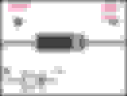
The part number for the suppressor is 9W8318K891BA. It's integral with the short harness that goes from the spoiler light disconnect and is about 12 inches in length. The suppressor does have a capacitor in it, but it's integrated into a circuit board with many components.
Mine is dead, hence no CHMSL. I've tried a web search and no luck. I also have a parts request into the "local" (60+ miles) Jaguar Dealer Parts Desk, but no reply yet.
From what I've read the capacitor is only used to prevent popping on the audio system - an open cap would not prevent the light from working from what I can see - if its shorted circuit then the led's are effectively short out which would probably blow a fuse.
That's the same schematic I used.
Anyway, there is a lot more stuff in that Suppressor than a capacitor:
There is a full 12V into this harness, but only 1.32V come out. This is weird, since the harness is in parallel. That's the way it is though.
The LED array works fine as I put 9V into it with a dry cell and LIGHT.
I was thinking maybe leave out the suppressor and add a big-*** resistor in Series between that 12v connector and the light array. It'd suck to burn something out though, like a chassis module or something.
Yer getting some where - I can't make out that black looking unit could it be an inline fuse.
I still think that surface mount transistor looking component is not passing current - check for voltage either side with some one holding the brake pedal down.
The transistor is open both directions. The "Inline Fuse" is just a black wire, for an additional Ground Wire.
Whatever those silver-black things are, (you didn't state) have continuity both ways so clearly not diodes. The tan-silver things are open both directions.
Going by all that, I'd assume the transistor, as you stated.
The capacitor holds and discharges fine also.
The part is removed from the car now, I'll check for voltage when I get a chance.
Really don't think it's a field effect, don't see why it would be.
ANYWAY, I replied to all this on that other thread. My bad for posting on two established threads anyway.
As in that other thread, CBE has zero continuity everywhere, so evidently toast.
I'll continue in the other thread and let this one die.
Post #13 third stop light not working
Yeah, can't see how two pins on one post would work out for a transistor. Weird though.
__________________
I mentioned that CJ after I took a look at the two leads going to the same foil on the left side - it may be some kind of zener diode (possibly twinned for current capability) to give some voltage regulation in combination with the silver and black/blue looking resistors.
Or it could be a simple diode combo in a single surface mount package:
Well then, probably that weird diode/transistor thing as full 12v before (which makes sense as it's directly from harness) and zero voltage after at the single post. And since no power past the diode thingy, no power to the capacitor at all. No power TO, then nothing out the negative side and back into the harness.
Seriously though, I don't understand the need for all this nonsense. All that would be needed to ensure the LED array doesn't get overpowered and burn up would be a single resistor, and maybe one diode to prevent feedback. Plus, why the capacitor? What would it power since the brake light gets constant power from the brake pedal circuit? Maybe to stabilize and reduce noise, but I can't see that as a problem.
Sheesh, I don't know.
Anyway, now maybe I should go to Radio Shack and get a diode, pull off that weird thing, resolder the diode in that spot and hope stuff works.
Thanks for the help, McJag
Radio shack carry 1N4001 to 4006 - all are 1 amp rated (I figure that should be adequate for led's - all of them are rated at well above 12 volts - I generally have a few 1N4004's hanging around)
Not sure if you know the correct polarity:
Last edited by McJag222; Nov 11, 2016 at 08:10 PM.
Plus, why the capacitor? What would it power since the brake light gets constant power from the brake pedal circuit?
Well, that's not true. The brake lights actually get a pulsing power signal. So the capacitor is to smooth it out so your lights don't flicker.
When I upgraded my 07 XK to have LED taillights, I had to add some circuitry to do that, as the original incandescent lamps would absorb the pulses via the lamp filaments and you wouldn't see the flicker.
Problem is, those 3-pin diode packages come in all flavours:
So, hard to tell which one you have, if it's open-circuit between all pin pairings and in all directions. But you do need to test between each pair and with both polarities to be sure.
Going by the way it's set up on the board, it would have to be BAR 15-1. Pin 1 and 2 are on the same circuit, and pin 3 needs to be the output.
Using my handy Phone App.....