
Curt hitch #11750 install

Thread Starter
|
Senior Member


Joined: Dec 2014
Posts: 592
Likes: 247
From: South Idaho
Curt hitch #11750 install
I know this may be blasphemy to some, and an insult to the Jaguar gods, but I installed a hitch on my late model x100. I am all about making the vehicles I own more useful and utilitarian, especially since the current ones double as work horses for me. On my x350 I installed a Jaguar roof rack and a Thule cargo basket in order to be able to carry more items. Seeing as my new project is a convertible, a roof rack is not an option. Regardless, I can more fully use the steel body of the x100's structure to carry weight via a hitch mount.
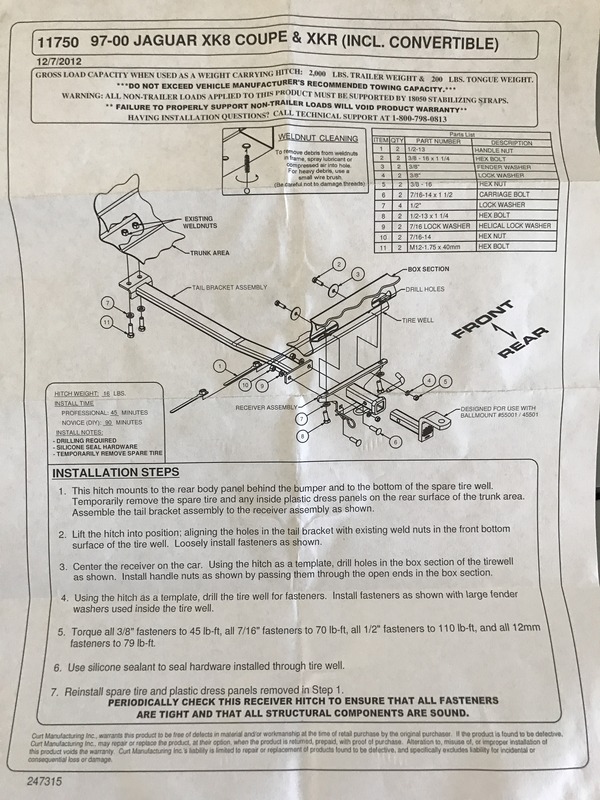
The Curt class 1 receiver hitch (model #11750) is designed for the earlier body x100's (Curt lists it as fitting 1997-2000) because the rear bumper cover rises higher than the later model x100's, and therefore does not interfere with the body. Installing this hitch on the earlier x100 is a direct bolt on process, while retrofitting it to later versions involves rear bumper modification. This involves the latter.
After shopping around online and finding a reasonably priced place with a decent local return policy, I purchased the Curt hitch from Home Depot and had it shipped to my door for $166. It came a few days later in a large Curt box wrapped with all the necessary hardware.

The instructions that came with it are very simple on a one sided piece of paper, and obviously do not address any body modification needed.
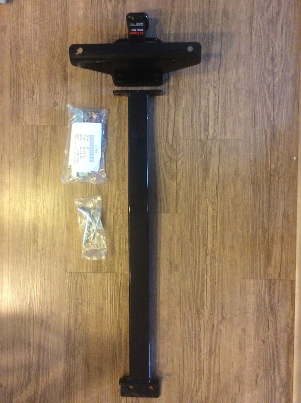
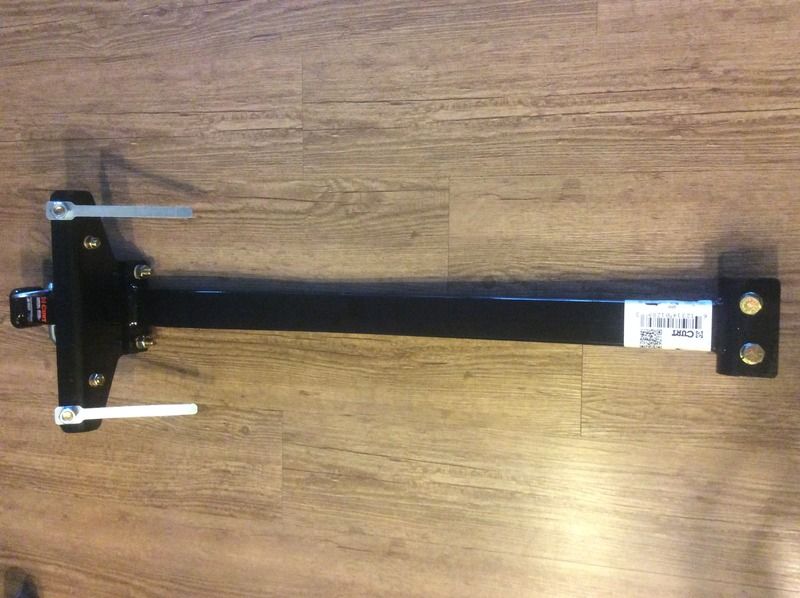
There are only a handful of bolts with their accompanying nuts and washers, along with two main pieces (a long slightly bent bar and the receiver end).
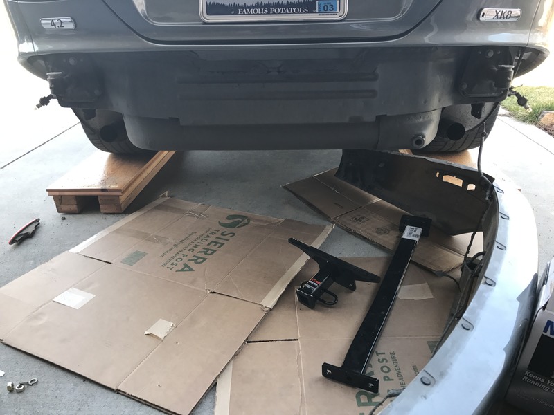
I wheeled the rear of the car onto ramps, setting the car in park with the parking brake on (use wheel chocks if needed).
I proceeded to remove the rear bumper. I thought I had read that bumper removal is not necessary for the hitch install (though that was probably for earlier x100's), but after installing the hitch I know I would have been fighting against the bumper since the hitch protrudes out to the rear so far. Plus I did not see a way to drill several of the holes without its removal, as there was no access.
I will not go into too much detail on the bumper removal, as it is documented quite well on the forum. I began by removing the rear exhaust tips and the pipes they are welded onto, which are secured on by single screws accessed at the bottom side of the exhaust. I did not need to remove any of the rear parking sensors, as the wiring came out of the right side of the car into the bumper and each sensor is wired in line. There are two large bolts that hold the bumper beam in place that are accessed where the exhaust tips were. The only other two bolts needed to remove the bumper are towards the front near the wheel well on either side. These bolts are not only used to hold the bumper in place, but also allows you to slide and tighten them down to correctly align the bumper to the fender. The lower lights on either side in the rear bumper also need to be disconnected. The sockets just rotate a partial turn and unscrew from the back side, leaving the bulbs dangling. I found it easier to unclip the lens cover (also from the back side, one on either side of the lens) and push the whole assembly through to the face of the bumper and then unscrew the bulb from the lens cover. Removing these gave me the ability to clean the dirt out from behind them. Rotate the bumper assembly to the right side of the car, pivoting it since the parking sensors are still attached by a wire. Be sure to set something down underneath the bumper if you are working on a coarse surface so as not to scratch the bumper.
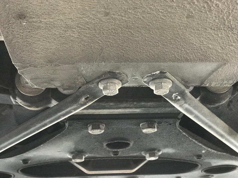
Unbolt the two tubular cross braces underneath at the front end of the boot well. The bolts were a bit stiff to get out, as they are triangular shaped.
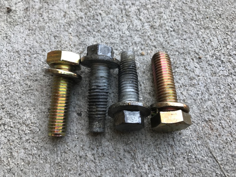
I replaced these with the supplied bolts, which are not triangular shaped and are easier to go in, but do have locking washers. Here are the old and new side by side:
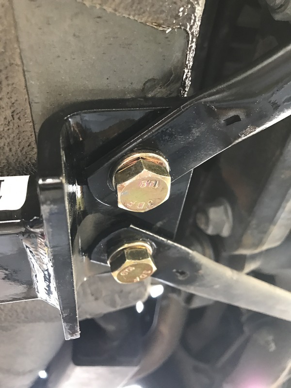
Using the supplied bolts, I loosely bolted the long hitch bar only to the car, without the receiver end, as it was lighter that way and easier to manage. Though the instructions did not specify which order they should go in, I opted to bolt the hitch bar directly against the car, with the cross brace ends underneath that.
At this point the rear of the bar will be hanging down.
I then attached the receiver end to the bar and tightened these bolts in far enough to hold it together firmly, but loose enough to still be able to push the unit up in place, as it will want to ride against the unibody protrusion at the rear of the boot well.
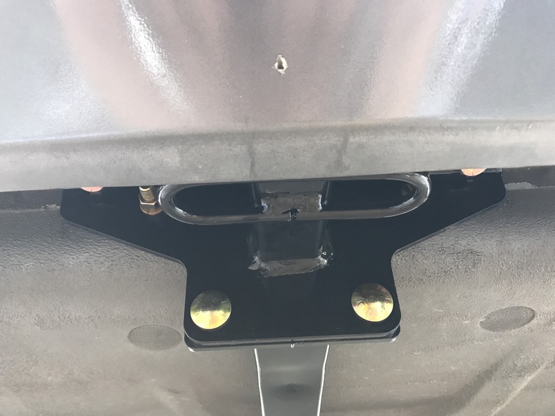
Two of the bolts go through the wide protrusion to the unibody on the rear of the boot well. I measured across this section from both sides and marked halfway, which was 9 7/8 inches on my car.
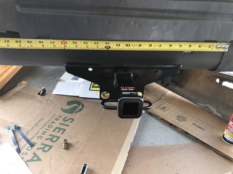
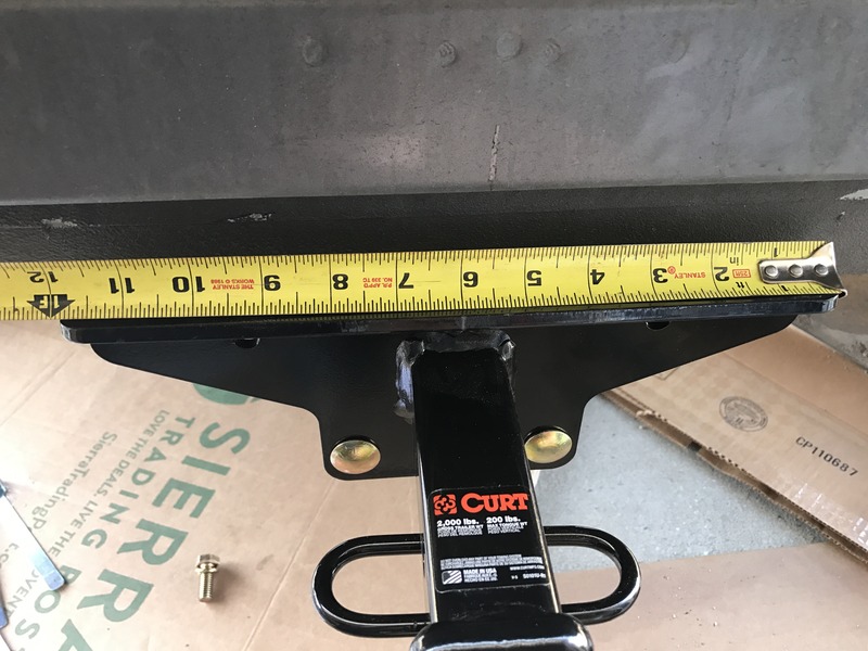
I measured from both sides on the top of the receiver and marked the middle point, which was 6 inches.
While the hitch is pushed upwards into place, I lined up the marks made to center, and marked the holes that would need to be drilled through the holes on the assembly with a Sharpie marker, then disconnected the two hitch pieces.
Though a bit more difficult, I first drilled the larger, upward angled holes into the unibody protrusion. It would have been easier to drill the smaller holes into the boot well first and then "hang" the whole unit on them while drilling the upper holes. The benefit this gave was that I could bolt the unit up and "suck" it upwards into place by tightening the larger bolts. This makes the placement closer to where it needed to be. If you first drill and bolt the boot well holes, the whole unit may hang lower than needed if your holes are not where they ought to be.
I bought a few extra hardened drill bits in case my bits broke, but my cheap black oxide Ryobi bits made it through the soft, thin unibody just fine.
First holes drilled:
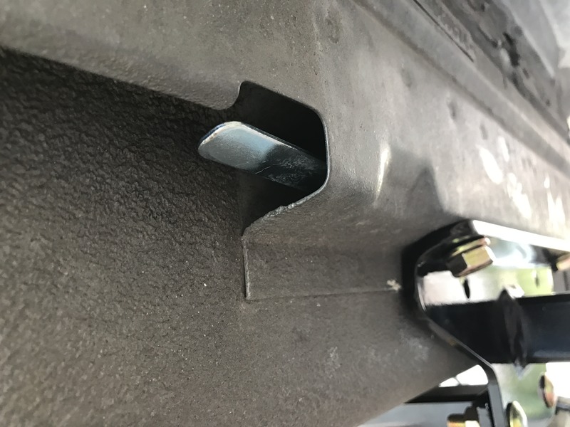
The larger bolts connect to one nut on either side that you slide inside the unibody protrusion using a long attached tab. It is a simple but neat way to get the nut deep enough inside the cavity so you can connect it to your bolt.
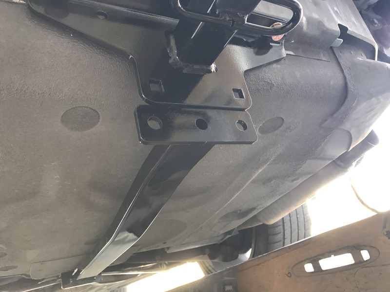
After bolting the receiver portion using the larger bolts and double checking center of the unit using the measured marks made earlier, tighten them sufficiently. I then reconnected the two hitch pieces together.
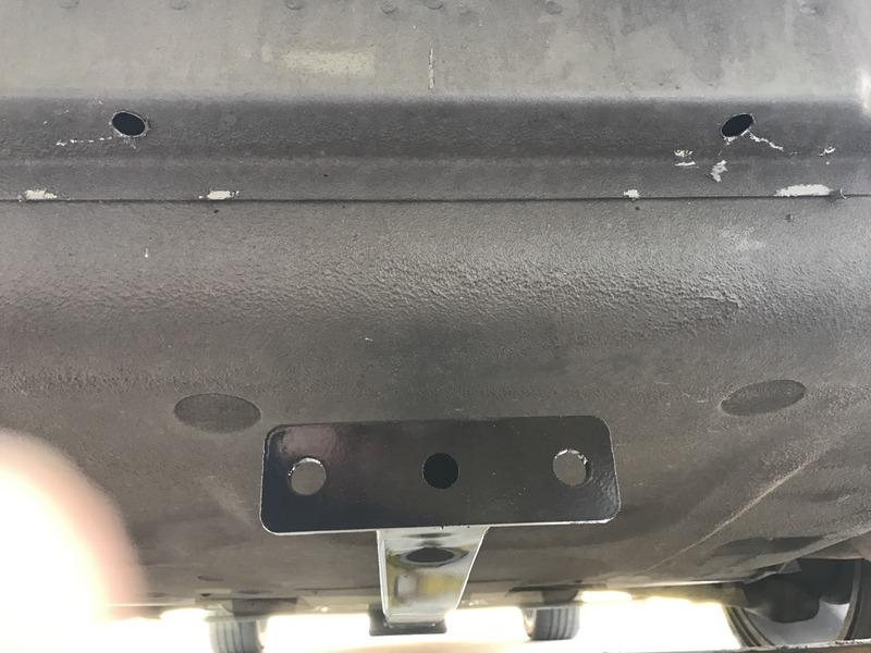
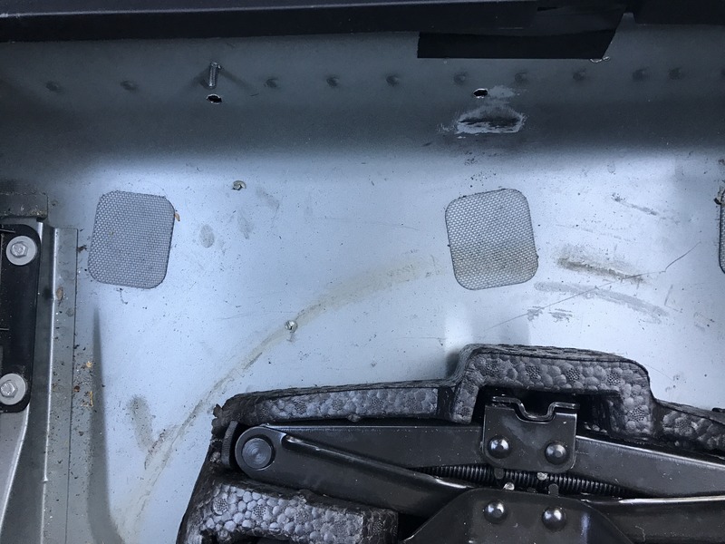
I used the hitch holes as a guide and drilled directly though them into the boot well while the receiver was bolted in place. One hole drilled:
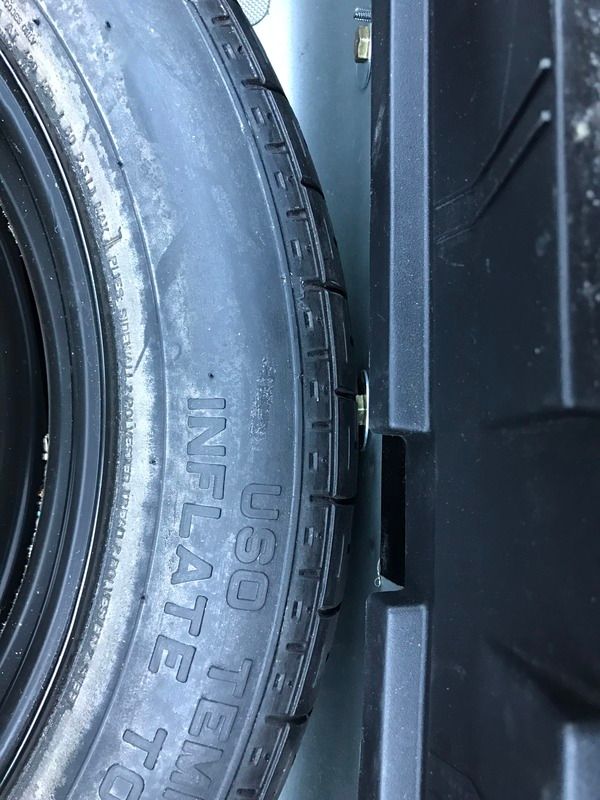
Be sure to take your spare tire out of the boot well as the holes come very close to where it rests.
You will also need room in order to place the nuts on the backside for the bolts to connect to.
I proceeded to tighten and torque everything else to spec.
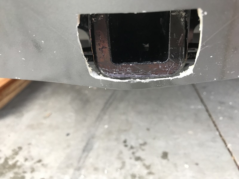
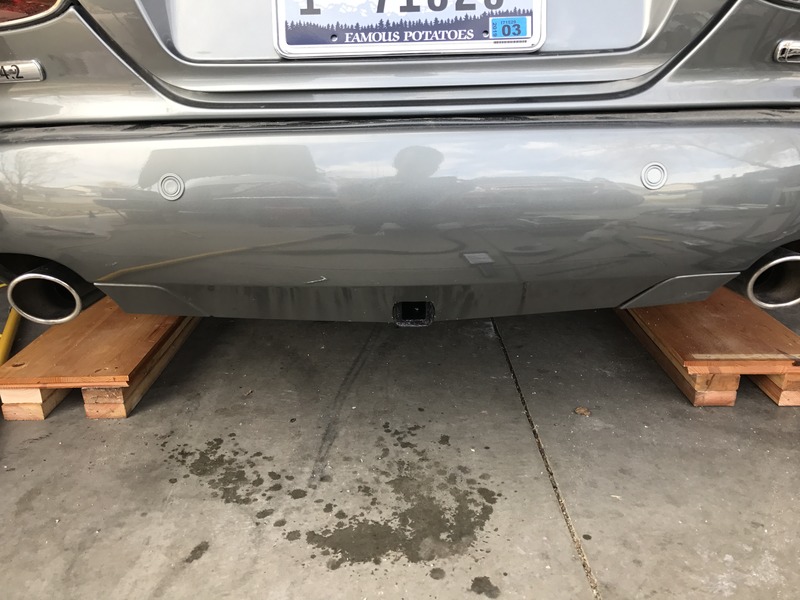
Now comes the trickier part with no instructions. Though you could probably do this a number of ways, I chose to loosely bolt the bumper back into place. At this point you will need to press the bumper forward and upward to get it into the correct place. I was able to bolt the bumper back up, though I didn't tighten the bolts completely down. When the bumper is in place, it will be bulging quite a bit where the hitch needs to poke through. I eyeballed and drilled a hole through the bumper cover into where the square receiver tube was, near the bottom of it since if anything the bumper was going to move upwards into place after the pressure was released and the hole was cut.
This gave me a start and I proceeded to use a sharp utility knife to slowly whittle away at the hole. I had a rotary tool on order at the time and as such didn't have access to it. Towards the end (postponed until the next day) I used the rotary tool and would recommend using it throughout, as the utility knife was slow and tedious, plus it scarred the face of the receiver tube (though I can fix it, I wouldn't do it again). I found the cutting discs to be the best attachment, and used the flex attachment on the rotary tool. Be sure to have multiple cutting discs, as you will probably break a few in the process. The bumper is especially thick near the bottom lip.
I wish there were a more accurate way to relay to you on how to cut the hole, but it really was just trial and error as there is no template and the bumper works itself into place as you cut and release pressure, so it is just slow going in order to get the placement right.
I bevelled the inside (back) edges of all my cuts in order to make the fitments easier against the hitch and to look better from the face. You can see the bevelled cuts here with the bumper pulled out a ways:
This gave me the ability to get even closer to the small sized hole I wanted and made it easier to fine tune the face side of the cover, as I could then just take the utility knife and take very small slivers off to make it look right on the face.
On the bottom side of the bumper cover you will need to make a wide notch so the safety hook connectors on the receiver will have room without interfering with the bumper. I found that if you nearly follow the bumper cover body line it is a good guide as to how much you need to notch back:
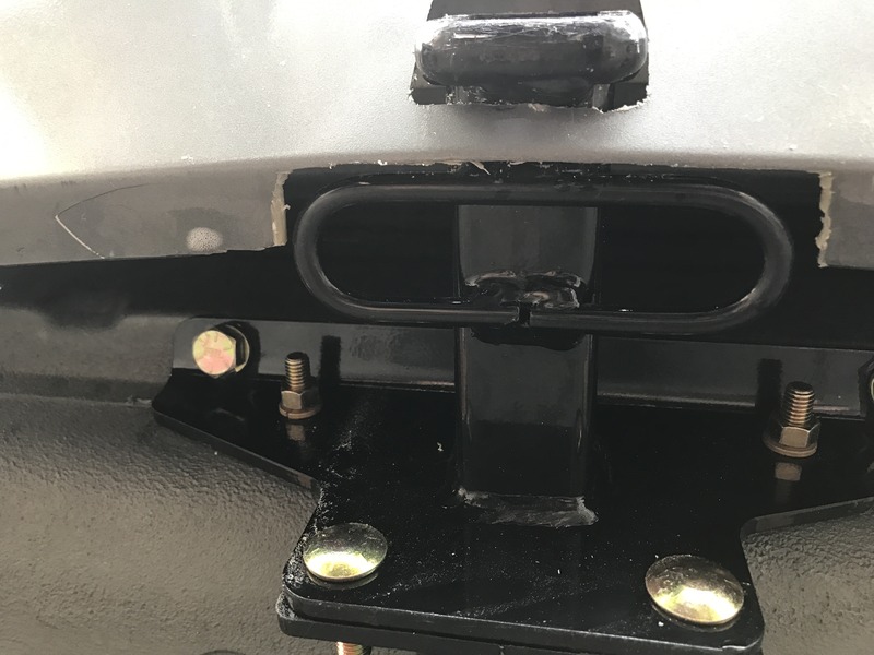
I chose to leave a strip of bumper cover connected directly under the square receiver tube (bumper is again pulled out in picture):
If you choose to do this you will need to bevel back the underneath portion of the bumper cover (the part you do not see) that rides against the receiver, as any bulk left in there will make the cover bulge outwards. In fact, after I cut underneath this part, my bumper still bulges slightly outwards at that point. I chose to go this route because even with the bulge, I think it looks better with the smallest hole possible in the bumper. The other option you have is to extend the vertical cuts you made for the receiver all the way to the bottom lip. This would negate any bulging but you may see the cut all the way down.
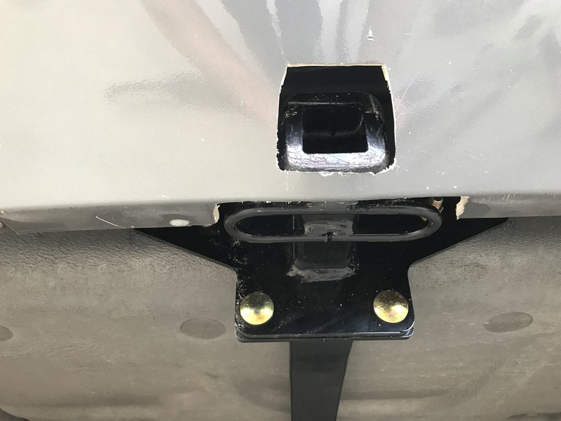
You can tell in the pictures I did not cut a square hole. It is a trapezoid, being narrower at the top and wider at the bottom. It needed to be wider at the bottom in order to clear the outside of the hitch tube, but I could get away with narrow at the top because it only needs to be wide enough for the hitch insert to plug into (the inside of the receiver tube).
By virtue of the slope of the bumper cover and the hitch tube not protruding out too far, it made this possible.
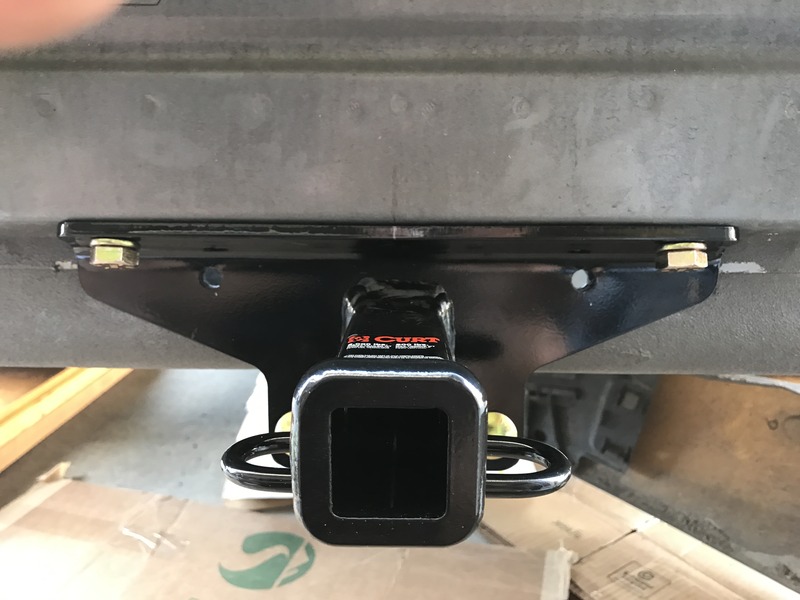
I think trapezoid shape I cut aided in making for a lower profile, less obvious hitch. The cuts may look a little rough around the edges, which they are, but once the bumper cover was pressed into place, I thought it looked pretty sharp. You can see the slight bulge downward in the bumper in this picture:
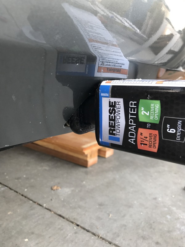
With the steep angle of the bumper, and because I needed to mate a 2" cargo hitch to it, I bought this adapter:
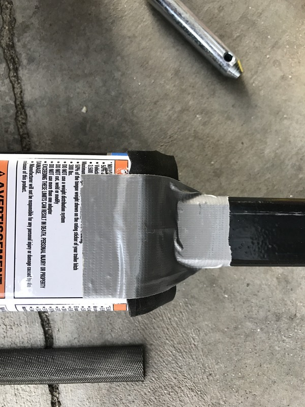
The adapter needs to be a bit longer, but works for the time being. I filed down the sharp upper edge of the adapter and attached a couple of pieces of bicycle tube rubber in between the adapter and bumper so no bumper scarring would occur, as it does fit tight.
Without rubber cushion:
With rubber cushion
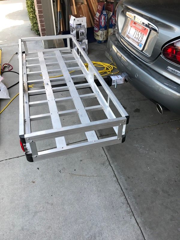
I have also noticed with the cargo carrier I am using, I need to find a hitch adapter with a sufficient rise in it but also long enough to clear the bumper in order to clear driveways and such, because it will scrape if not careful. If you are using a 1 1/4" inch cargo carrier, a lot of them come built in with a riser so you won't have this problem. I just wanted something heavier duty and also had this one on hand, so it is what I'm using at the moment:
Along with this hitch bag:
Here's a pic with the cargo basket on. It's a bit wide for my tastes, bit does alright for now:
As a side note, because of the multiple joints I have going from a 1 1/4" receiver to an adapter to a 2" cargo carrier, and because like all hitch accessories they are not machined to close tolerances, I found the necessity to shim the receiver and adapter tubes to make them tighter tolerances with less play so that the cargo carrier would be more rigid and also not drag as much when exiting driveways. I cut strips from a flat license plate (not the old style with the raised lettering) and slid them inside the receivers on the bottom side to take up space as metal shims. I was able to use three long shims in the Curt receiver and one long shim in the adapter. It took most of the play out and makes it so it doesn't scrape much at all anymore even when it is loaded down with weight.
Overall I am pleased with the Curt hitch and fitment. I need to work on the cargo carrier for my use, but that is outside the scope of this writeup and does not affect the purpose of it.
The Curt hitch is rated for 200 lbs tongue weight and 2000 lbs towing capacity. Curt states that the warranty is voided if you use non trailer loads without their stabilizing straps. I did not purchase the straps and do not plan to at this time. Though it might not be a bad idea to have, the places (or lack thereof) to securely connect the straps to concern me more than using the rack without them.
I'll try to get more pictures soon with it all loaded down.
Thanks for reading!
I know this may be blasphemy to some, and an insult to the Jaguar gods, but I installed a hitch on my late model x100. I am all about making the vehicles I own more useful and utilitarian, especially since the current ones double as work horses for me. On my x350 I installed a Jaguar roof rack and a Thule cargo basket in order to be able to carry more items. Seeing as my new project is a convertible, a roof rack is not an option. Regardless, I can more fully use the steel body of the x100's structure to carry weight via a hitch mount.
The Curt class 1 receiver hitch (model #11750) is designed for the earlier body x100's (Curt lists it as fitting 1997-2000) because the rear bumper cover rises higher than the later model x100's, and therefore does not interfere with the body. Installing this hitch on the earlier x100 is a direct bolt on process, while retrofitting it to later versions involves rear bumper modification. This involves the latter.
After shopping around online and finding a reasonably priced place with a decent local return policy, I purchased the Curt hitch from Home Depot and had it shipped to my door for $166. It came a few days later in a large Curt box wrapped with all the necessary hardware.

The instructions that came with it are very simple on a one sided piece of paper, and obviously do not address any body modification needed.

There are only a handful of bolts with their accompanying nuts and washers, along with two main pieces (a long slightly bent bar and the receiver end).


I wheeled the rear of the car onto ramps, setting the car in park with the parking brake on (use wheel chocks if needed).
I proceeded to remove the rear bumper. I thought I had read that bumper removal is not necessary for the hitch install (though that was probably for earlier x100's), but after installing the hitch I know I would have been fighting against the bumper since the hitch protrudes out to the rear so far. Plus I did not see a way to drill several of the holes without its removal, as there was no access.
I will not go into too much detail on the bumper removal, as it is documented quite well on the forum. I began by removing the rear exhaust tips and the pipes they are welded onto, which are secured on by single screws accessed at the bottom side of the exhaust. I did not need to remove any of the rear parking sensors, as the wiring came out of the right side of the car into the bumper and each sensor is wired in line. There are two large bolts that hold the bumper beam in place that are accessed where the exhaust tips were. The only other two bolts needed to remove the bumper are towards the front near the wheel well on either side. These bolts are not only used to hold the bumper in place, but also allows you to slide and tighten them down to correctly align the bumper to the fender. The lower lights on either side in the rear bumper also need to be disconnected. The sockets just rotate a partial turn and unscrew from the back side, leaving the bulbs dangling. I found it easier to unclip the lens cover (also from the back side, one on either side of the lens) and push the whole assembly through to the face of the bumper and then unscrew the bulb from the lens cover. Removing these gave me the ability to clean the dirt out from behind them. Rotate the bumper assembly to the right side of the car, pivoting it since the parking sensors are still attached by a wire. Be sure to set something down underneath the bumper if you are working on a coarse surface so as not to scratch the bumper.

Unbolt the two tubular cross braces underneath at the front end of the boot well. The bolts were a bit stiff to get out, as they are triangular shaped.

I replaced these with the supplied bolts, which are not triangular shaped and are easier to go in, but do have locking washers. Here are the old and new side by side:

Using the supplied bolts, I loosely bolted the long hitch bar only to the car, without the receiver end, as it was lighter that way and easier to manage. Though the instructions did not specify which order they should go in, I opted to bolt the hitch bar directly against the car, with the cross brace ends underneath that.

At this point the rear of the bar will be hanging down.
I then attached the receiver end to the bar and tightened these bolts in far enough to hold it together firmly, but loose enough to still be able to push the unit up in place, as it will want to ride against the unibody protrusion at the rear of the boot well.
Two of the bolts go through the wide protrusion to the unibody on the rear of the boot well. I measured across this section from both sides and marked halfway, which was 9 7/8 inches on my car.

I measured from both sides on the top of the receiver and marked the middle point, which was 6 inches.

While the hitch is pushed upwards into place, I lined up the marks made to center, and marked the holes that would need to be drilled through the holes on the assembly with a Sharpie marker, then disconnected the two hitch pieces.
Though a bit more difficult, I first drilled the larger, upward angled holes into the unibody protrusion. It would have been easier to drill the smaller holes into the boot well first and then "hang" the whole unit on them while drilling the upper holes. The benefit this gave was that I could bolt the unit up and "suck" it upwards into place by tightening the larger bolts. This makes the placement closer to where it needed to be. If you first drill and bolt the boot well holes, the whole unit may hang lower than needed if your holes are not where they ought to be.
I bought a few extra hardened drill bits in case my bits broke, but my cheap black oxide Ryobi bits made it through the soft, thin unibody just fine.
First holes drilled:

The larger bolts connect to one nut on either side that you slide inside the unibody protrusion using a long attached tab. It is a simple but neat way to get the nut deep enough inside the cavity so you can connect it to your bolt.

After bolting the receiver portion using the larger bolts and double checking center of the unit using the measured marks made earlier, tighten them sufficiently. I then reconnected the two hitch pieces together.

I used the hitch holes as a guide and drilled directly though them into the boot well while the receiver was bolted in place. One hole drilled:

Be sure to take your spare tire out of the boot well as the holes come very close to where it rests.

You will also need room in order to place the nuts on the backside for the bolts to connect to.

I proceeded to tighten and torque everything else to spec.
Now comes the trickier part with no instructions. Though you could probably do this a number of ways, I chose to loosely bolt the bumper back into place. At this point you will need to press the bumper forward and upward to get it into the correct place. I was able to bolt the bumper back up, though I didn't tighten the bolts completely down. When the bumper is in place, it will be bulging quite a bit where the hitch needs to poke through. I eyeballed and drilled a hole through the bumper cover into where the square receiver tube was, near the bottom of it since if anything the bumper was going to move upwards into place after the pressure was released and the hole was cut.

This gave me a start and I proceeded to use a sharp utility knife to slowly whittle away at the hole. I had a rotary tool on order at the time and as such didn't have access to it. Towards the end (postponed until the next day) I used the rotary tool and would recommend using it throughout, as the utility knife was slow and tedious, plus it scarred the face of the receiver tube (though I can fix it, I wouldn't do it again). I found the cutting discs to be the best attachment, and used the flex attachment on the rotary tool. Be sure to have multiple cutting discs, as you will probably break a few in the process. The bumper is especially thick near the bottom lip.
I wish there were a more accurate way to relay to you on how to cut the hole, but it really was just trial and error as there is no template and the bumper works itself into place as you cut and release pressure, so it is just slow going in order to get the placement right.
I bevelled the inside (back) edges of all my cuts in order to make the fitments easier against the hitch and to look better from the face. You can see the bevelled cuts here with the bumper pulled out a ways:

This gave me the ability to get even closer to the small sized hole I wanted and made it easier to fine tune the face side of the cover, as I could then just take the utility knife and take very small slivers off to make it look right on the face.
On the bottom side of the bumper cover you will need to make a wide notch so the safety hook connectors on the receiver will have room without interfering with the bumper. I found that if you nearly follow the bumper cover body line it is a good guide as to how much you need to notch back:

I chose to leave a strip of bumper cover connected directly under the square receiver tube (bumper is again pulled out in picture):

If you choose to do this you will need to bevel back the underneath portion of the bumper cover (the part you do not see) that rides against the receiver, as any bulk left in there will make the cover bulge outwards. In fact, after I cut underneath this part, my bumper still bulges slightly outwards at that point. I chose to go this route because even with the bulge, I think it looks better with the smallest hole possible in the bumper. The other option you have is to extend the vertical cuts you made for the receiver all the way to the bottom lip. This would negate any bulging but you may see the cut all the way down.
You can tell in the pictures I did not cut a square hole. It is a trapezoid, being narrower at the top and wider at the bottom. It needed to be wider at the bottom in order to clear the outside of the hitch tube, but I could get away with narrow at the top because it only needs to be wide enough for the hitch insert to plug into (the inside of the receiver tube).
By virtue of the slope of the bumper cover and the hitch tube not protruding out too far, it made this possible.

I think trapezoid shape I cut aided in making for a lower profile, less obvious hitch. The cuts may look a little rough around the edges, which they are, but once the bumper cover was pressed into place, I thought it looked pretty sharp. You can see the slight bulge downward in the bumper in this picture:

With the steep angle of the bumper, and because I needed to mate a 2" cargo hitch to it, I bought this adapter:
The adapter needs to be a bit longer, but works for the time being. I filed down the sharp upper edge of the adapter and attached a couple of pieces of bicycle tube rubber in between the adapter and bumper so no bumper scarring would occur, as it does fit tight.
Without rubber cushion:

With rubber cushion

I have also noticed with the cargo carrier I am using, I need to find a hitch adapter with a sufficient rise in it but also long enough to clear the bumper in order to clear driveways and such, because it will scrape if not careful. If you are using a 1 1/4" inch cargo carrier, a lot of them come built in with a riser so you won't have this problem. I just wanted something heavier duty and also had this one on hand, so it is what I'm using at the moment:
Along with this hitch bag:
Here's a pic with the cargo basket on. It's a bit wide for my tastes, bit does alright for now:

As a side note, because of the multiple joints I have going from a 1 1/4" receiver to an adapter to a 2" cargo carrier, and because like all hitch accessories they are not machined to close tolerances, I found the necessity to shim the receiver and adapter tubes to make them tighter tolerances with less play so that the cargo carrier would be more rigid and also not drag as much when exiting driveways. I cut strips from a flat license plate (not the old style with the raised lettering) and slid them inside the receivers on the bottom side to take up space as metal shims. I was able to use three long shims in the Curt receiver and one long shim in the adapter. It took most of the play out and makes it so it doesn't scrape much at all anymore even when it is loaded down with weight.
Overall I am pleased with the Curt hitch and fitment. I need to work on the cargo carrier for my use, but that is outside the scope of this writeup and does not affect the purpose of it.
The Curt hitch is rated for 200 lbs tongue weight and 2000 lbs towing capacity. Curt states that the warranty is voided if you use non trailer loads without their stabilizing straps. I did not purchase the straps and do not plan to at this time. Though it might not be a bad idea to have, the places (or lack thereof) to securely connect the straps to concern me more than using the rack without them.
I'll try to get more pictures soon with it all loaded down.
Thanks for reading!
Last edited by chillyphilly; Apr 9, 2017 at 10:49 AM. Reason: Had to re add pictures so they would show up
Senior Member

Joined: Sep 2016
Posts: 360
Likes: 201
From: Las Vegas, NV
Wonderful detailed article, chillyphilly! I am planning an extended cross-county tour in my XK8 later this year and have been wondering if I could feasibly bring my 25 cubic foot pull-behind motorcycle trailer so my girlfriend can take enough shoes with her... Your instructions make it dead-simple!
Junior Member
Joined: Jan 2020
Posts: 6
Likes: 0
From: las vegas
Great job on the installation and thank you for the details. I have a 2007 XK and was wondering if the installation would be the same or is there a different hitch that might fit my XK better?
Veteran Member
Joined: Oct 2014
Posts: 1,757
Likes: 748
From: Eau Claire, WI.
Curt Mfg. started with "curt" and his father in law (my boss at the time) going to an auction together and by pure chance/accident purchased a crate of new hitch *****. He then went around and sold them to the local auto shops one by one. True story I saw the crate. We at the time were importing forgings for the dairy industry so he had an inside track to overseas manufacturers. He then built it into a multi million dollar business and sold it off in his thirties. It's an odd feeling seeing a millionaire created right next to you and you never even knew there was a ship leaving. Who you know and being in the right spot at the right time... helps.


Thread
Thread Starter
Forum
Replies
Last Post
migrosmarket
XJ XJ8 / XJR ( X308 )
6
May 9, 2015 04:22 PM
Currently Active Users Viewing This Thread: 1 (0 members and 1 guests)