
Steering Tilt motor Pot values by position FYI


Thread Starter
|
Veteran Member
Joined: Apr 2014
Posts: 5,457
Likes: 1,816
From: New Jersey USA
Hi, The other day I said I would measure and share the tilt motor's monitoring mechanism's values (resistance in this case) by wire/position.
There are 5 wires into the tilt motor. Two power wires (Red and Brown) and 3 wires to monitor position all connected to the potentiometer (Pot): Pink (K); White Blue (W/BL); White Green (W/G).
The resistance between the W/BL and W/G wires is 2.21 ohms in all tilt positions. Continuity between the power wires and the 3 monitoring wires is open. (no connection)
When looking from the drivers seat facing forward into the white tilt motor's female mechanical connector, I rotated the white connector counter clock wise fully. This represents be the Steering Wheel Tilted Down all the way.
Inside the motor: In this position the Potentiometer's gear is at the bottom of the larger green gear's threads (this larger green gear is connected directly to the motor). This fact will help you index and align the motor, the Pot and the Steering wheel's position should you ever have to install a tilt motor.
Readings tilted all the way down:
Pink to W/BL is 2.07 ohms; Pink (K) to W/G is 194 ohms.
Tilted 1/4 of the way up (from the all the way down position):
K to W/BL is 1.6 ohms; K to W/G is 0.65 ohms.
Tilted 1/2 way up:
K to W/BL is 1.125 ohms; K to W/G is 1.125 ohms
Tilted 3/4 way up:
K to W/BL is 0.65 ohms; K to W/G is 1.6 ohms
Tilted all the way up:
K to W/BL is 209 ohms; K to W/G is 2.04 ohms
As mentioned above, W/BL to W/G is 2.21 ohms in all tilt positions.
Let's just say this is an ongoing attempt to build our knowledge around this troublesome component. I'm going to try to think of a way to prove that these resistance values are the key to the tilt motor's dead reckoning to recall positions.
Someone mentioned that the fail-safe mechanism may be monitoring a steady change in these values as the tilt moves, indicating no problems and allowing it to continue moving. I'm not sure if that's true or the mechanism may use these values to dead reckon to specific positions. If you can think of a benefit in testing / proving These hypothesis, please share it. The test would be pretty easy, just not sure of the benefit.
I figure if we put our heads together we can solve this issue and get everyone's tilt/reach to work as designed.

Senior Member
Joined: Jul 2011
Posts: 568
Likes: 192
From: Jacksonville
Someone mentioned that the fail-safe mechanism may be monitoring a steady change in these values as the tilt moves, indicating no problems and allowing it to continue moving. I'm not sure if that's true or the mechanism may use these values to dead reckon to specific positions. If you can think of a benefit in testing / proving These hypothesis, please share it.
I had removed the entire black box assy from my tilt motor during my testing, and the connected the motor to the car again and the tilt worked flawlessly, however, the memory function did not work at all. Based on this, I belive the pot just indicates location/position.
Why the tilt stops working is because the the worm gear gets stuck (I know this to be the case on mine anyhow) because it slightly dislodges from its seat and jams up the motor. After carefully dissecting my assembly, I beleive what happens is that the tension washer weakens over time, allowing the worm gear to dislodge slightly, jamming up the motor. I determined this after doing what others had done - remove the tension washer. This worked temporarily, but the problem quickly returned. After removing the gear and cleaning and re-lubing a few times, and the problem still was coming back, I decided to inspect closely, and then replaced the tension washer, this time bending it a bit to give it more tension. This resolved the issue for over a year before the issue returned. I have not looked for a replacement new tension washer, but plan to see if I can find one. I beleive this will resolve the problem long term.
Last edited by SteveJacks; Apr 10, 2015 at 09:33 PM.
Thread Starter
|
Veteran Member
Joined: Apr 2014
Posts: 5,457
Likes: 1,816
From: New Jersey USA
Steve I think you are right, that's what I meant by "using the values for dead reckoning." Sorry if it wasn't clear. In other words if it reads 1.125 ohms it is 1/2 way down. What you tested seems to prove that hypothesis.
Not sure how or where we can leverage the knowledge of these resistance values but someone of us may need them somewhere someday.
I've got something else to figure out, while the memory and the auto position work perfectly, the switch (up down in out) doesn't work at all right now. Wouldn't it be something if there was a cold solder on the Body Processor Module? Thanks for your commment.
Hey come to think of it, let me ask: When you had the black plastic module (what I call the Pot) off, did the movement stop at the extremes (all the way up, all the way down) by itself? If so, that proves the black plastic module does not monitor the extremes by itself either. There must be some circuit breaker or heat trip switch to cut the current and prevent burning out the motor at the extremes of motion - where it can't move any further. This would probably apply if it runs into some unexpected glitch preventing the intended movement.
Senior Member
Joined: Apr 2014
Posts: 167
Likes: 73
From: Sweden
Hi.
Greate job! Reverse engeneering is a good way to understand stuff.
I do challenge your findings a bit. The values of the pot seems to be totally off. You would never have such low values on a potentiometer as there would be too much interference from Cable length and coroded connectors.
Are you sure you do not want to add a K to some of the measurments of ohms? 2.2K seems legit, but it is probably just a typeo.
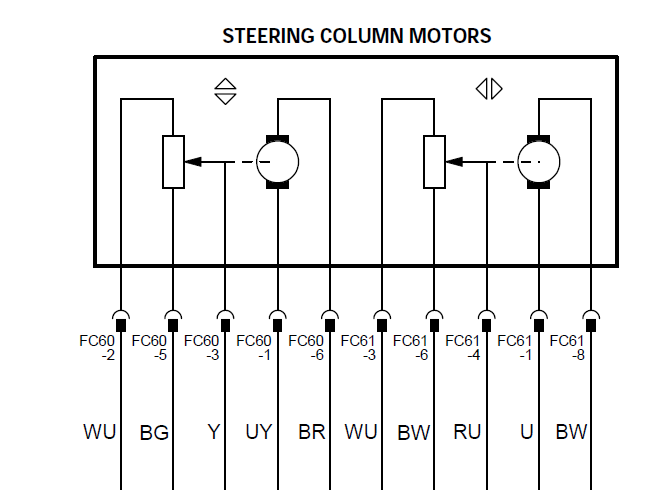
This is from the electricals pdf. (2001 edition)
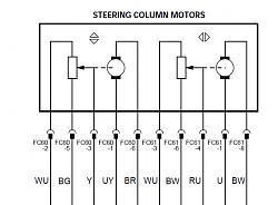
I guess the left one is the one we are talking about.
Typically in a sloution like this you drive the motor untill you pass a requested value of the pot, (stored with the memory key in the computer in this case) and then stop.
There could also be limits programmed to what is the maximum and minimum values and the computer would not allow the motor to get passed these limits to protect the mechanics.
Also a current monitor on the motor feed (probably in the inside the BPM) checks that the motor is not running hot. This is what I Believe is the one that shuts down the tilt on everyones cars.
Typically these potentiometers would be about 1-5k (5-10k on 24v systems) to keep a low current. The BPM will measure between WU and BG (1), between BG and Y (2) and between WU and Y (3).
If the values 2 + 3 are not the same as value 1 you have a faulty pot and some code should be fired.
As I have said in previous posts, I Believe Jaguar swapped the current sensors for the tilt and telescope (reach). The tilt is not as strong as it should be, and the telescope is so strong it breaks the mechanical driveline. I Think they have them the wrong way around.
Anyways, this is not a way to misscredit you, just to explain how I Think it is made based on other Electric gizmos.
/Daniel
Greate job! Reverse engeneering is a good way to understand stuff.
I do challenge your findings a bit. The values of the pot seems to be totally off. You would never have such low values on a potentiometer as there would be too much interference from Cable length and coroded connectors.
Are you sure you do not want to add a K to some of the measurments of ohms? 2.2K seems legit, but it is probably just a typeo.
This is from the electricals pdf. (2001 edition)
I guess the left one is the one we are talking about.
Typically in a sloution like this you drive the motor untill you pass a requested value of the pot, (stored with the memory key in the computer in this case) and then stop.
There could also be limits programmed to what is the maximum and minimum values and the computer would not allow the motor to get passed these limits to protect the mechanics.
Also a current monitor on the motor feed (probably in the inside the BPM) checks that the motor is not running hot. This is what I Believe is the one that shuts down the tilt on everyones cars.
Typically these potentiometers would be about 1-5k (5-10k on 24v systems) to keep a low current. The BPM will measure between WU and BG (1), between BG and Y (2) and between WU and Y (3).
If the values 2 + 3 are not the same as value 1 you have a faulty pot and some code should be fired.
As I have said in previous posts, I Believe Jaguar swapped the current sensors for the tilt and telescope (reach). The tilt is not as strong as it should be, and the telescope is so strong it breaks the mechanical driveline. I Think they have them the wrong way around.
Anyways, this is not a way to misscredit you, just to explain how I Think it is made based on other Electric gizmos.
/Daniel
Last edited by zecretw; Apr 11, 2015 at 04:53 AM.
Thread Starter
|
Veteran Member
Joined: Apr 2014
Posts: 5,457
Likes: 1,816
From: New Jersey USA
Daniel, Thanks for the diagram. Guess they changed the colors from 1998's, but this sure helps.
I'll recheck the ohm values, was using a new auto - ranging meter at 3am. You make a good point about the missing k(?).
I'd love to get my hands and meter on that current limiting device. I bet that is preventing the movements via the steering wheel switch. Then don't you know it, as soon as I type that I realize the incongruity - No decent engineer would allow the auto function and the memory circuits to operate outside of the current limiting circuit. Both those functions work perfectly. Like I said in another post, guess it's time to recheck continuity across the switch and the switch connections. Everything either points to a swinging switch fault or the presence of an entirely different circuit protection path for the auto/memory circuit and the switch circuit.
Daniel, please do keep you ideas and comments coming. I appreciate it.
Senior Member
Joined: Apr 2014
Posts: 167
Likes: 73
From: Sweden
Flattering will make me do anything.
Are you having a problem with only the steering Wheel manual movement or also seat movement? Then it could be fuse 8 (10A) on the driverside fusebox that is blown as it gives Power to the manual lot.
If it is only the Wheel, then bring out your new meter and make it woth its Money.
Here is Another Picture from the electrical manual that I recommend you to download from the forum. Everything is on here.
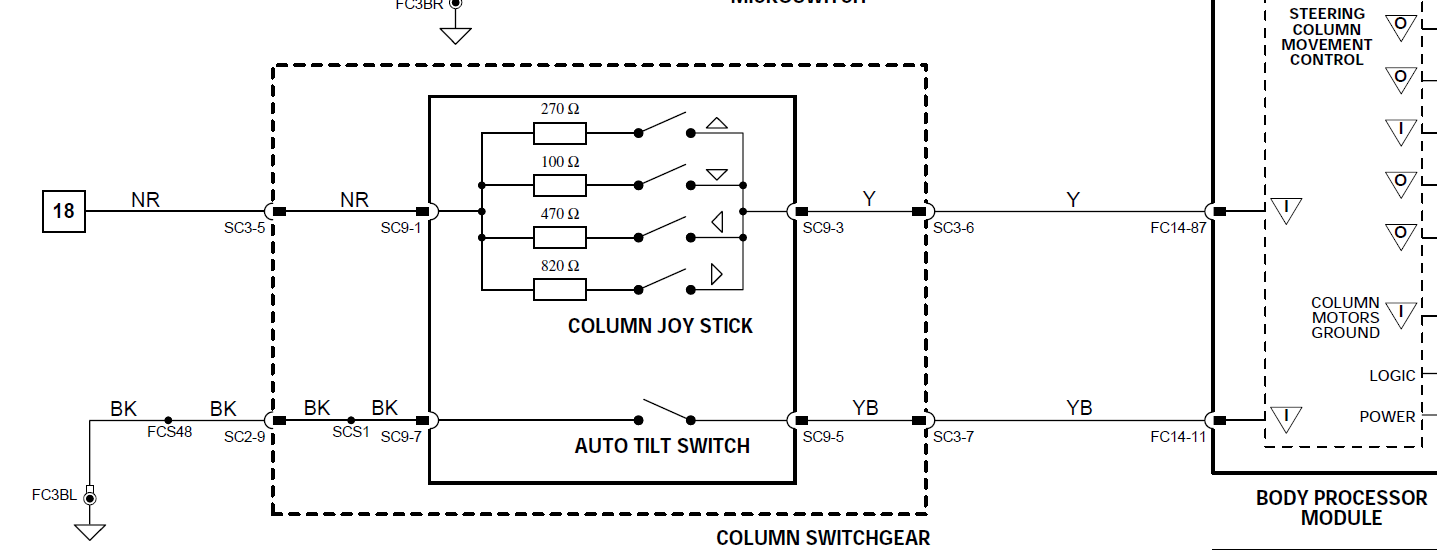
Here you can clearly see where to measure to get an idea on where the problem may lie.
/Daniel
Senior Member
Joined: Jul 2011
Posts: 568
Likes: 192
From: Jacksonville
Hey come to think of it, let me ask: When you had the black plastic module (what I call the Pot) off, did the movement stop at the extremes (all the way up, all the way down) by itself? If so, that proves the black plastic module does not monitor the extremes by itself either. There must be some circuit breaker or heat trip switch to cut the current and prevent burning out the motor at the extremes of motion - where it can't move any further. This would probably apply if it runs into some unexpected glitch preventing the intended movement.

Thread
Thread Starter
Forum
Replies
Last Post
FS[Western US]: XJS Wiper Motor Upgrade- 76-88 - Electrolux Style
XJsc-guy
PRIVATE For Sale / Trade or Buy Classifieds
0
Sep 2, 2015 11:43 AM
Currently Active Users Viewing This Thread: 1 (0 members and 1 guests)