
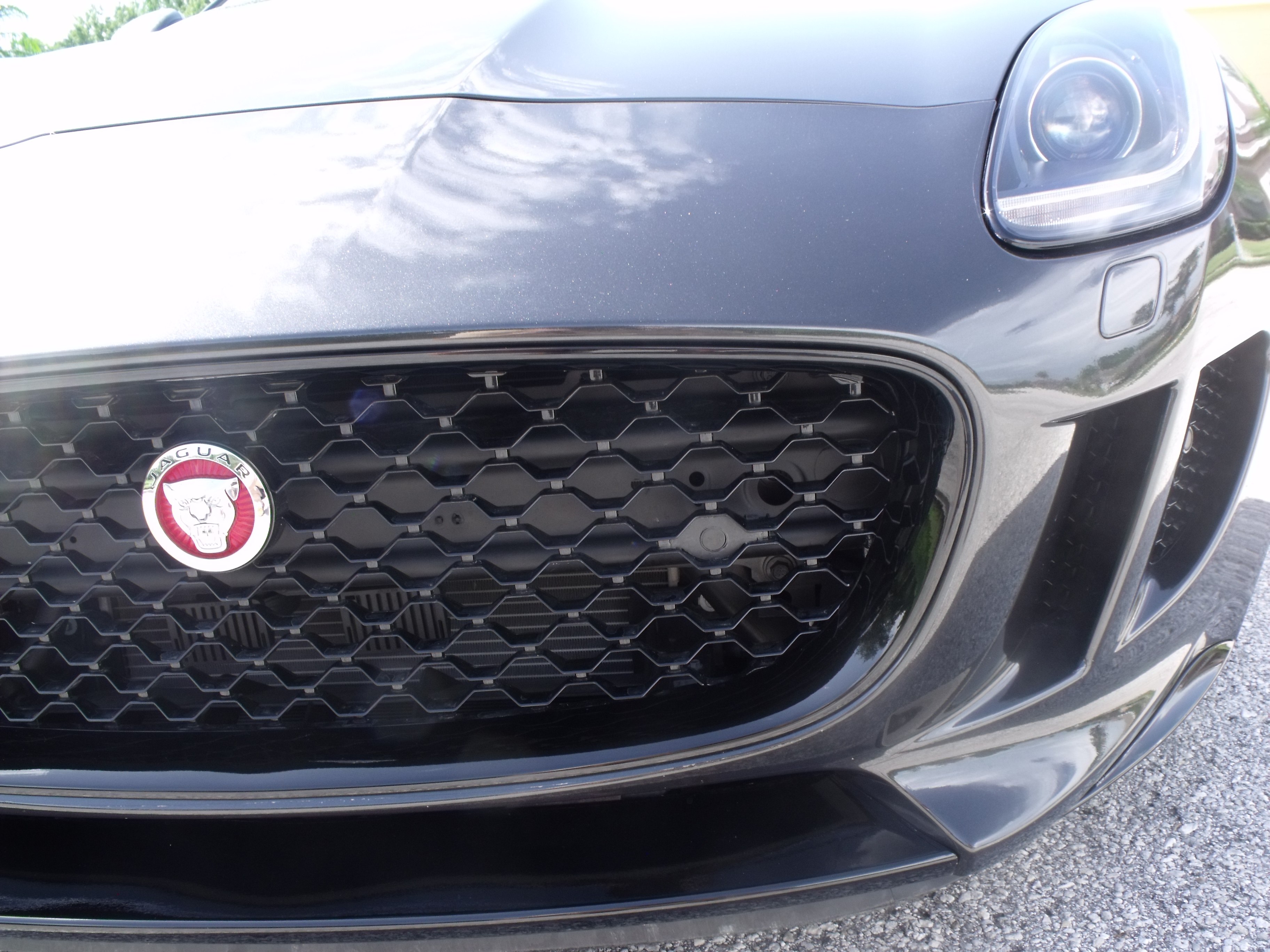
P 7 Bumper-less Grille Installed


Veteran Member
Joined: Feb 2016
Posts: 1,571
Likes: 334
From: kelowna
put the wire in a loom or paint in black along with the bar; use a wire support to keep it in place......I think you guys are overthinking it a bit; it won't be much of an issue when everything is flat black. not like the grill bar was made to look particularly nice.
If you look at dozens of other vehicles, you'll find that many examples of "stuff" behind the grill.....it is common and generally ignored. I spent hours discussing the proper method and pattern of black overspray on one of my collector car forums....basically the assy line method was to blast everything behind the grill with a hap-hazzard pattern of black paint. That said, if you want to try to "make nice" behind the grill, knock yourself out; no harm, no foul.
Dave


At 150 mph, nobody will see any of that crap.
Regarding the color code of the gloss black honeycombe, I doubt that it exists. Coloring plastic is an entirely different process. So looking for a match in paint will be a question of testing or getting a paint shop to scan the grille and come up with a close match.
Please let us know if you come by a code.
Please let us know if you come by a code.
Here's the R&R instructions you asked me for:
I'll work on it this weekend. I also need to locate the male and female connectors so that the harness wires can be extended without splicing.
Guten Tag Meister Kajo. Hier ist das Entwurf: Vermessungen sind mm.
Last edited by Unhingd; May 21, 2017 at 10:48 AM.

Member
Joined: Apr 2017
Posts: 85
Likes: 8
From: London
Thanks for the technical drawing, personally I would loose the 2 side protrusions and keep it as a simple hexagon.
I used the dimensions from a drawing posted much earlier on this thread and they were too small. I had a design studio laser cut a piece of 3mm high gloss black plastic using the dimensions given and it didn't fit unless you wanted to fill the edges with silicone! So I gave the design studio the honeycomb grille and after using measuring callipers they are now working on a new sample.
I have decided and I realise its subjective but it looks much neater without the "wings".
Member
Joined: Apr 2017
Posts: 85
Likes: 8
From: London
It is imperative that the optical sensors are placed as far forward as possible, therefore the insert must be fixed to the front of the grille so as not to be affected by the sides of the honeycomb. Hence my suggestion not to fit the side sections or wings.
I have tested the operation of the sensors and this is absolutely the case
I have tested the operation of the sensors and this is absolutely the case
Given my bracket design, even with the tabs on the back of the grille, I believe the face of my sensors will be positioned 2-3mm more forward than those in the picture. I agree that those tabs have to be hidden, or not there at all. If I need the sensor even more forward, the tabs can be trimmed off.
Member
Joined: Apr 2017
Posts: 85
Likes: 8
From: London
Agreed, I carried out a sensor test on Friday in conjunction with the owner of the body shop that I patronise. He convinced me by testing, using a series of boxes to simulate a kerb and then a wall. The sensors only worked correctly when the front of the sensors are parallel with the front of the grille. Any recessing inside the honeycomb resulted in false or intermittent accuracy.

Senior Member
Joined: Jun 2014
Posts: 682
Likes: 245
From: Southern Cal
Agreed, I carried out a sensor test on Friday in conjunction with the owner of the body shop that I patronise. He convinced me by testing, using a series of boxes to simulate a kerb and then a wall. The sensors only worked correctly when the front of the sensors are parallel with the front of the grille. Any recessing inside the honeycomb resulted in false or intermittent accuracy.
This install in set back inside the honeycomb, and I seem to recall this owner's sensors worked correctly...
Member
Joined: Apr 2017
Posts: 85
Likes: 8
From: London
Apparently so but in our testing it was not the case.
To prevent any false indications it must be preferable to flush mount them into the front of the honeycomb.
Provided the octagon is cut neatly, preferably by laser with the tabs trimmed! It will not look out of place, it really has to be the best solution.
To prevent any false indications it must be preferable to flush mount them into the front of the honeycomb.
Provided the octagon is cut neatly, preferably by laser with the tabs trimmed! It will not look out of place, it really has to be the best solution.
Senior Member
Joined: Oct 2016
Posts: 163
Likes: 41
From: Bavarian, GER
How do we do it now?Does the technical drawing have to be changed again?What I do not quite understand is how the adapter should hold? Do we have to stick it?What sensors do we need? The straight lines or the angles? And how do we do it with cable extension?
Member
Joined: Apr 2017
Posts: 85
Likes: 8
From: London
Make a template from cardboard to check the dimensions are correct and the cut out fills the aperture correctly. Once done have someone laser cut a piece of high gloss 3mm ABS to the same shape, with the an appropriate hole to retain the sensor.
Yes you will have to use adhesive to fix the hexagon into the honeycomb aperture and the same to retain the sensor.
As for the wiring yes it will have to be cut and extended, there is no alternative. You will then have to hide the wires as best as possible. Regarding the sensors it depends on the reach, so long as they fit through the hole either type will do.