When you click on links to various merchants on this site and make a purchase, this can result in this site earning a commission. Affiliate programs and affiliations include, but are not limited to, the eBay Partner Network.
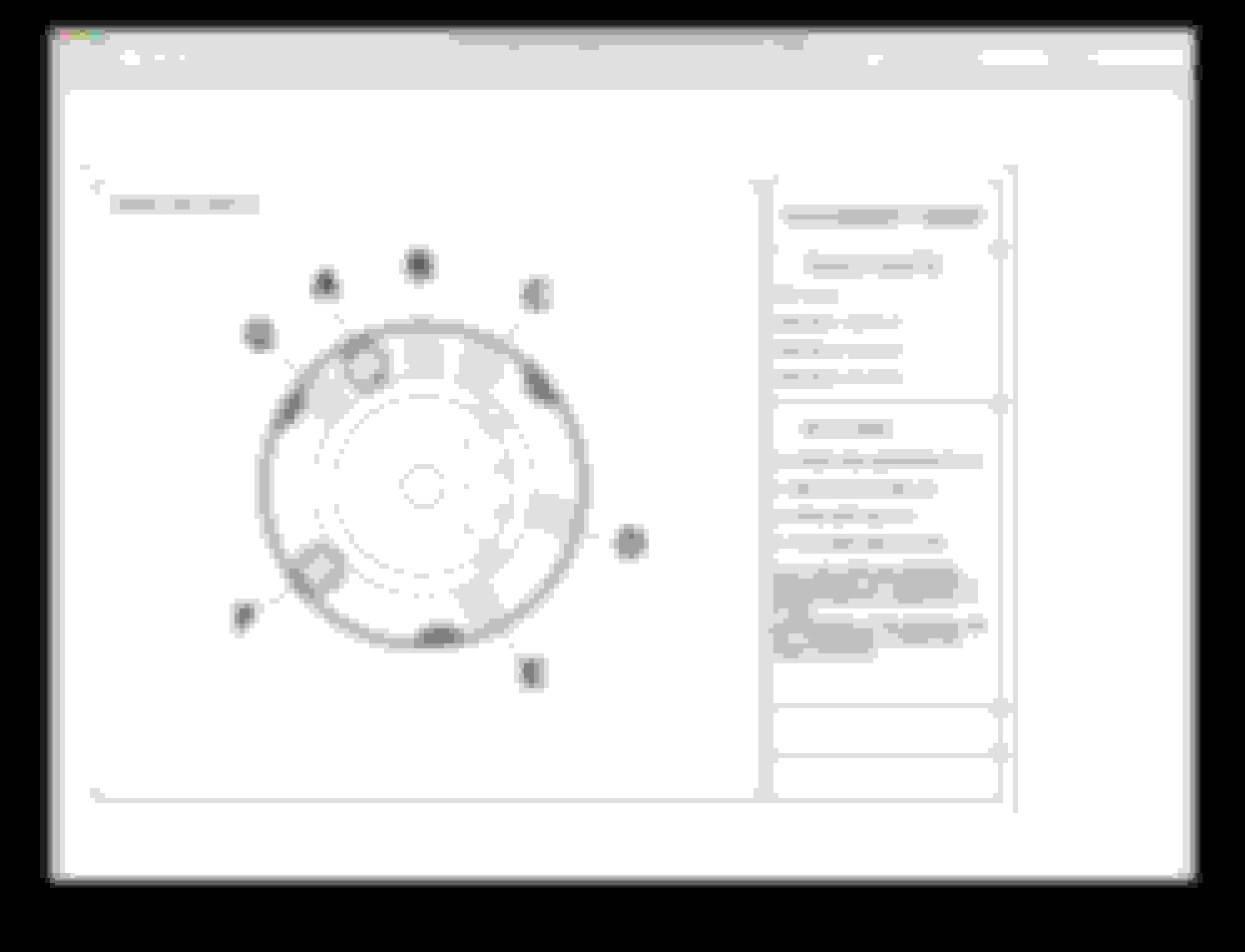
Here is a wiring diagram for the new light switches
New light switch
It is quite different from the original in terms of wire positioning, and there are no markings on it. SNG Barratt provided it to me. I was stumped without it. I am replacing the original switch as it does not have the fog light position (and probably doesn't work anyway).
Recently found that the window chrome is no longer available from my normal part source, so Jose was kind enough to provide some used ones. I got them chromed and they turned out ver well. We will see how the fit ultimately, but the look great and seem to have retained their shape and flexibility. So going used is an option!
Re-done chrome trim
(The stool in the car is to sit on while doing electrical work, not my new seating plan)
I was able to get all 4 window pieces re-chromed for $280 at a local chrome place.
I am sure your finisher could be redone nicely for less than $100.
SNG Barratt still sells the connector pieces. It will be months before I actually install them though. I still have to do my headliner and I am in no hurry to tackle that task.
Finally resolved my issues with getting the engine to crank with the starter-the jumper cables did not carry enough amps to turn the engine, so when I hooked the starter through normal batter cables, it cranked just fine. I just wanted to make sure it would work before I completed the assembly.
I have not had much time for the car the last few weeks, but hope to finish the wiring this week so I can go ahead and get the engine and front end put back in.
Chuck, this is gonna sound like a total newb question but I may have said that I was not a "car guy" until I got my Jag.
Where/ what spec are you using for the auto wiring and connectors? I have a LOT of old, flaky wiring that I do not trust on a cross-country trip. When I look into my engine compartment I see many sketchy splices too.
Gene-
I have been getting supplies from British Wiring (https://www.britishwiring.com).
They sell all the little pieces and wires you would need, except for the 10 pin connector in the engine compartment which you can get from SNG Barratt.
Wiring parts stash
Handy tool for getting the bullets into the connectors.
10 pin connector
If there is any one area you might look at is the light wiring connectors in the engine compartment as mine had turned to goo, and were really unsafe if they even worked. I still have all the wires tagged as to what they are until I finish checking all the lights and wiring.
If you decide to tackle this, I can talk you through it on the phone.
If I have to replace wires, I order the specific color and size from British wiring. That way I keep everything matching the wiring diagram. I had to replace all my wiper motor wires for example. Also, I don't crimp the bullets on the end of the wire, but solder them on. You make enough of the wire bare so the bare wire sticks out the end of the bullet. Solder it, and then clip the tip. Gets a good connection.
I have a question about wiring up relays in a positive ground car. Would the high power fused feed to the relay (30) be accomplished by attaching the wire to the body, and the relay ground wire (85) to the power feed?
Or does it not really matter for a relay as long as you have a ground and power feed?
I am working on installing an air conditioning system and want to run the engine cooling fan through a relay.
Thanks!
Chuck, in this instance that would be completely correct, if you think of electric current as a flow of water that flows from positive to negative, your positive is your feed, the fact that the body of the car is the connection for the feed makes no difference, the principle still applies.
Coils (inside the relay)do not care which way they are connected, but the magnetic field they create would be reversed so the contact would be trying to go the opposite direction (trying to open more) rather than close, so if it is the wrong way round it won't harm it, but it will not switch over.
Some DC motors (universal motors) are not polarity sensitive as the field winding and armature both get changed in polarity the magnetic fields also both change so the motor rotates the same direction.
If the motor has a permanent magnet field then this stays fixed and the reversing the polarity would then make the motor turn the opposite direction as only one magnetic field is reversed.
So in general anything that is a resistive load does not care which way it is connected (light bulb), but anything that has a semiconductor (Radio) or creates a magnetic field (Relay) is polarity sensitive (there are exceptions as always but these are more complicated to explain)
If you get in a pickle with the air conditioning and the trinary switch etc. email me the wiring diagram and I will mark it up and send it back for you.
The fan connections are fine, but actually you can connect these either way as it is just a switch, just remember to connect the positive side of the fan to your ground, and switch the 0V side through the relay.
The coil connections are the wrong way round in you diagram, pin 85 is defined as ground connection by the manufacturers, so will be 0V, and the switch line pin 86 is 12v trigger.
On positive earth, the chassis is not switched, so you need to connect that to 86 as it is 12v, and switch 85 to 0V.
Attached schematic showing the correct connections.
I hope this makes sense, if it's not clear let me know.
Well, I did get the wiring for the AC finished. Decided to quit fiddling with the other wiring for now and do some real work. So over the last week or so, I have managed to install the rear bumper, and with the rear end down on the ground now, had the stability to install the engine. I also got the headliner installed. It is a challenge in the 1960 cars due to the recessed sun visors, but with got it figured out. So I was also able to install the rear interior lights, the back deck panel, and the rear window. Also installed the front end today. So it is really coming together. I am working on some of the front window, exterior chrome, and measuring furflex around the doors. I ordered some screws from LeBaron Bonney, so I should be able to install the wood trim around the headliner as well. All this is in preparation for door re-assembly and installation.
Eventually I will get back to the wiring, and get the engine all hooked up. Months and months away from completion, but it is nice to finally make some visible progress. If anyone wants details on the headliner installation, I can share that but it wasn’t as bad as I feared.
Engine mounted
Working on the back of the headliner
Seat, rear deck lid and headliner material around the lower back of the rear window
I'll be very interested in how you go installing the rear window chrome trim.
Mine keeps "springing" off!
Great pics, by the way.
When I did mine I applied glue and then fitted a section of it a time and then taped it with 2" wide masking tape, once I got it all in it seemed to hold well but its getting it in thats the problem.
Just to be sure I wired the two halfs together using the holes already in the trim, I stripped some electrical cable to provide a copper locking wire as it won't rust.
I also used an original trim rather than a reproduction, I don't have any experience of reproductions to be fair but if its not quite right I can see it being difficult if not impossible to fit. Its kind of amazing that they could make things like that accurate enough back in the 1950/60's.