When you click on links to various merchants on this site and make a purchase, this can result in this site earning a commission. Affiliate programs and affiliations include, but are not limited to, the eBay Partner Network.
I finally have the time to cut into one of my old struts, it does have rubber seals but they are not user replaceable. Will post more photos in a few days.
This process took several days as I had to accomplish this task during lunch..... I will not dissemble the strut assembly for obvious safety reasons but, I am interested in looking at the electrical components that are part of the CATS…
There are 3 user replaceable O-Rings, 2 on the Air valve and 1 under the nut on top of the Strut Rod where the electrical connector attaches.
One question comes to mind - are there any markings on the air bladder that might give us a clue as to the original manufacturer and a part number? If you decide to remove the clamps on the bladder, could you measure the bladder's various dimensions, such as I.D./O.D. at both ends and overall length?
One question comes to mind - are there any markings on the air bladder that might give us a clue as to the original manufacturer and a part number? If you decide to remove the clamps on the bladder, could you measure the bladder's various dimensions, such as I.D./O.D. at both ends and overall length?
Thanks!
Don
I noticed a bar code on the bladder but I didn't look at it. I will take some photos next week, it is at work and I wont be there till next week. I will be going to Glenview, IL for the weekend.
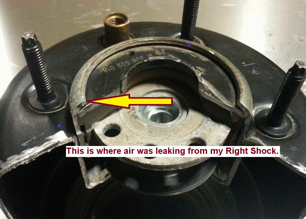
Another question occurs to me. The cold-temperature air leak on our front right shock is coming from the inside of the large red rubber cylinder visible in this photo (I don't know why the photo rotated this way):
When you have time, would you be willing to cut a V-section out of that red cylinder and whatever is inside it so we can see the internal cross-sectional view? I'll understand if there's a reason you don't want to cut into it, but if I could see the internal arrangement of the components, I might be able to figure out a method of sealing the leak on our shock.
Thanks again - you are adding some amazingly helpful information to our collective knowledge of the air suspension!
Cheers,
Don
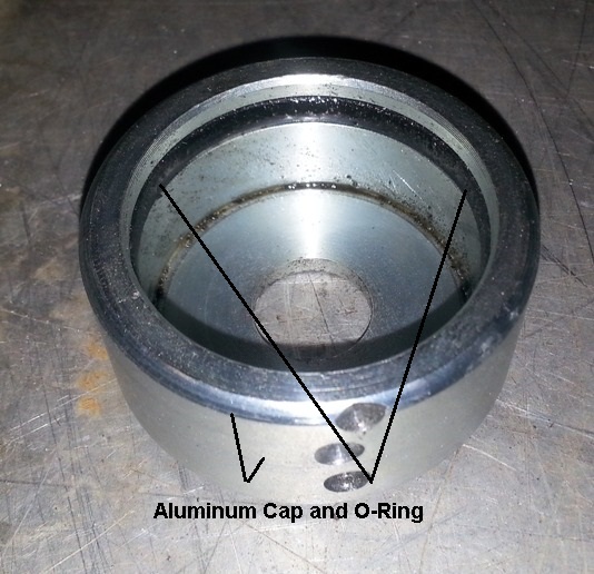
Here are a few cut-aways of the strut-top mount bushing:
Here are a few cut-aways of the strut-top mount bushing:
Thanks reyesl!
These photos support what I've assumed has been the cause of the cold-weather leak in our front right air spring. My assumption is that the large rubber mounting/seal hardens over time and loses some of its compliance. In cold temperatures, the large metal spool-shaped component contracts in diameter, creating a path for air to escape between the contracted metal and the hardened rubber. Does that analysis make sense?
Assuming that is the case, I am now pondering a method of sealing the leak without disassembling the air spring/damper assembly. More to come.
Thanks again for these very, very helpful photos!!!
Cheers,
Don
That was my assumption also, that is the main reason I undertook this task...
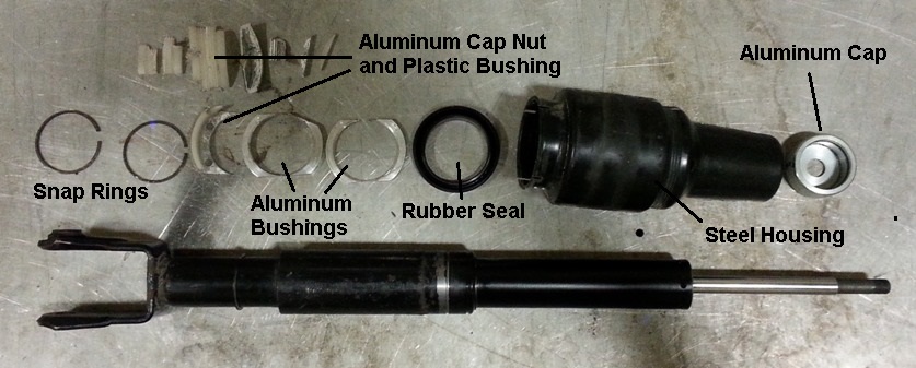
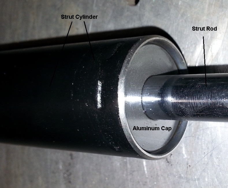
Another photo of the components.....
I believe that is a Polyurethane Bushing as it is hard to compress, I couldn't insert the top plate.
Thanks for the additional photos - they provide exactly the kind of inside view I've dreamed of!
Now that you've dissected this unit, can you describe the process Arnotts would go through to rebuild one of these? If I'm not mistaken, the rebuilt Arnotts units did not come with outer dust covers, so they must have just cut off the original covers and not worried about replacing them. Probably not a problem, since plenty of vehicles (Mercedes, Land Rover) have exposed air bladders. Aside from replacing the air bladder, what else do you think Arnotts could have replaced? O-rings? Lower shock bushing?
Thanks for the additional photos - they provide exactly the kind of inside view I've dreamed of!
Now that you've dissected this unit, can you describe the process Arnotts would go through to rebuild one of these? Aside from replacing the air bladder, what else do you think Arnotts could have replaced? O-rings? Lower shock bushing?
Thanks,
Don
Now that might be another project? If anyone has an old Arnott unit, I would be glad to dissect it.
As well as keeping the air pressure in, that red(ish) moulding also seems to be a vibration isolator like you get at the top of normal shocks. This might explain why it eventually starts to leak air. The constant movement will eventually cause it to lose its sealing ability.
Any pictures of the electrical connector that is in the top center of the shock. Still not sure how the shock is able to switch fron Hard to Soft setting based on getting an electrical charge or not.
Any pictures of the electrical connector that is in the top center of the shock. Still not sure how the shock is able to switch fron Hard to Soft setting based on getting an electrical charge or not.
Magnetorheological shocks are all pretty much the same, Cadillac and Corvette started with them in the early '90s. Inside any shock is an orifice that limits oil flow as the shock moves up and down. In electronic shocks, the fluid is homoginized with ferrous material, and around the orifice is an electromagnet. This mechanism allows the orifice to be "varied" by a varying magnetic field. As the coil current increases, magnetic field increases, and the fluid slows (appears to be made thicker) which equals firm damping. With no magnetic field, the fluid is thin and you get soft damping.
The shock just needs a +V supply to energize the coil, ground is provided by the body. Variable damping is achieved with PWM of the coil current.
As the coil current increases, magnetic field increases, and the fluid slows (appears to be made thicker) which equals firm damping. With no magnetic field, the fluid is thin and you get soft damping.
Hi mhamilton,
Thanks for sharing this info! It all makes sense, except if I'm not mistaken, in Jaguar's CATS/ECATS implementation the default ride with no voltage to the coil is "Firm," and the PWM signal to the coil activates "Soft" mode. Does that agree with your understanding of the Jaguar system's operation? Perhaps I've just assumed this was the case based on the many members who have reported their suspensions going hard when a malfunction caused the CATS Fault message to be displayed.
Cambo scoped the ECATS signal on his X350 and if I recall correctly it was 5V/400Hz. Whether the pulse width actually changes dynamically I do not know.
Cheers,
Don
It's certainly possible that they designed the shocks to default to the firm setting when voltage is lost. It's not intuitive, as loss of the voltage signal would mean loss of coil current. But I'm certain it can be done. Maybe they installed a permanent mangnetic and the coil actualy counters that magnetic force.
On the Cadillacs, if you disconnected the shock wires it would default to a soft ride, as you would expect. It's possible also that these are not using a MR fluid, but rather just an electronically valved shock. Cadillac had these before the MR shocks ("MagnaRide" wasn't until the late '90s IIRC) MagneRide - Wikipedia, the free encyclopedia. Prior to that system the shocks had a variable orifice that physically varied the orifice size to 3 discrete settings. That could easily be designed to default to firm. I doubt that Jag (or rather Bilstein) would design something using that old technology, but you never know. Also see Active suspension - Wikipedia, the free encyclopedia
400Hz sounds correct for most PWM controls. If it's the same technology as GM, I'm guessing it does allow full dynamic control through the range of the shock. There'd be no reason to have a high frequency signal if it was a simple solenoid.