i purchased a 98 jaguar xjr about 3 months ago and have been doing a mini restore on the car. A past owner had installed a cheap aftermarket stereo in the car and I want to put it back to factory.
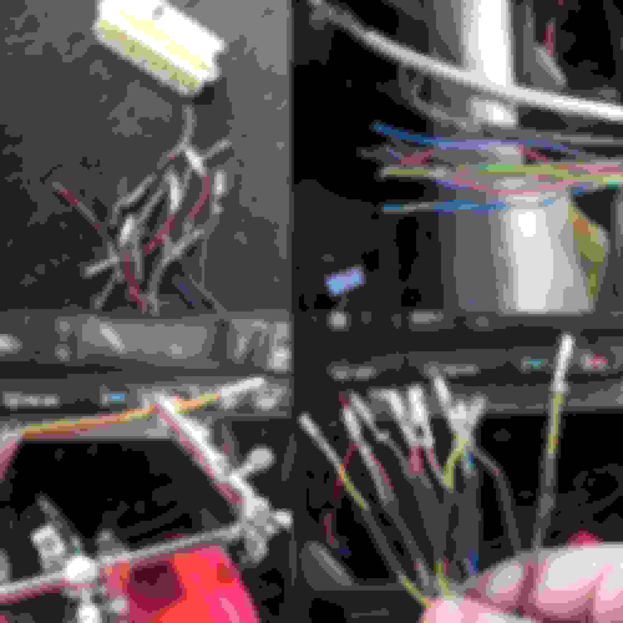
To my shock, they had just cut off all 3 of the factory connectors front and back. At least in the back they left the connectors semi attached to the cable so I can see the pin out in back but not front.
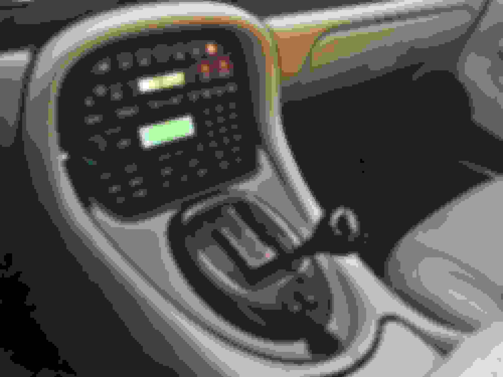
I have the premium option with the alpine head unit and amp in trunk with Harmon Kardon speakers.
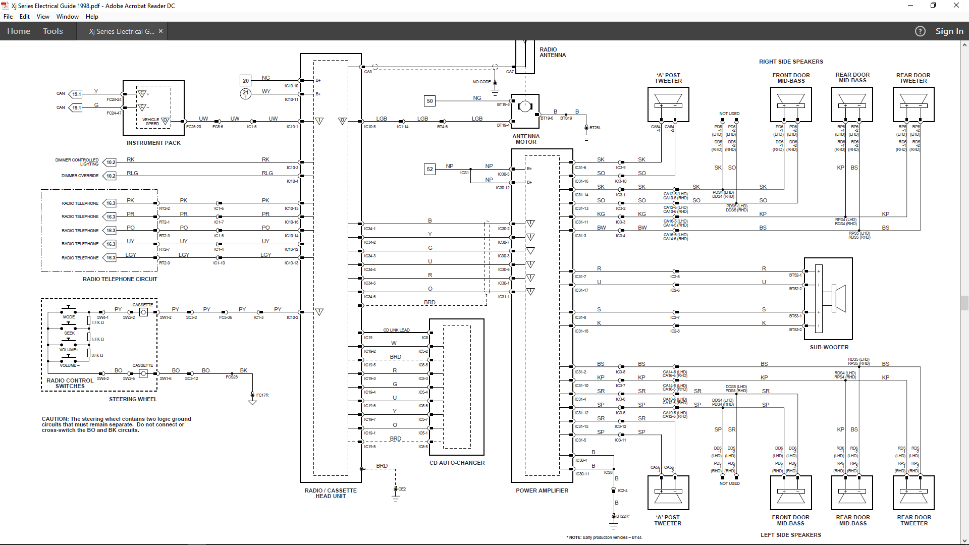
I finally found a wiring diagram for the gray 6 pin din pre amp out that I think is correct.
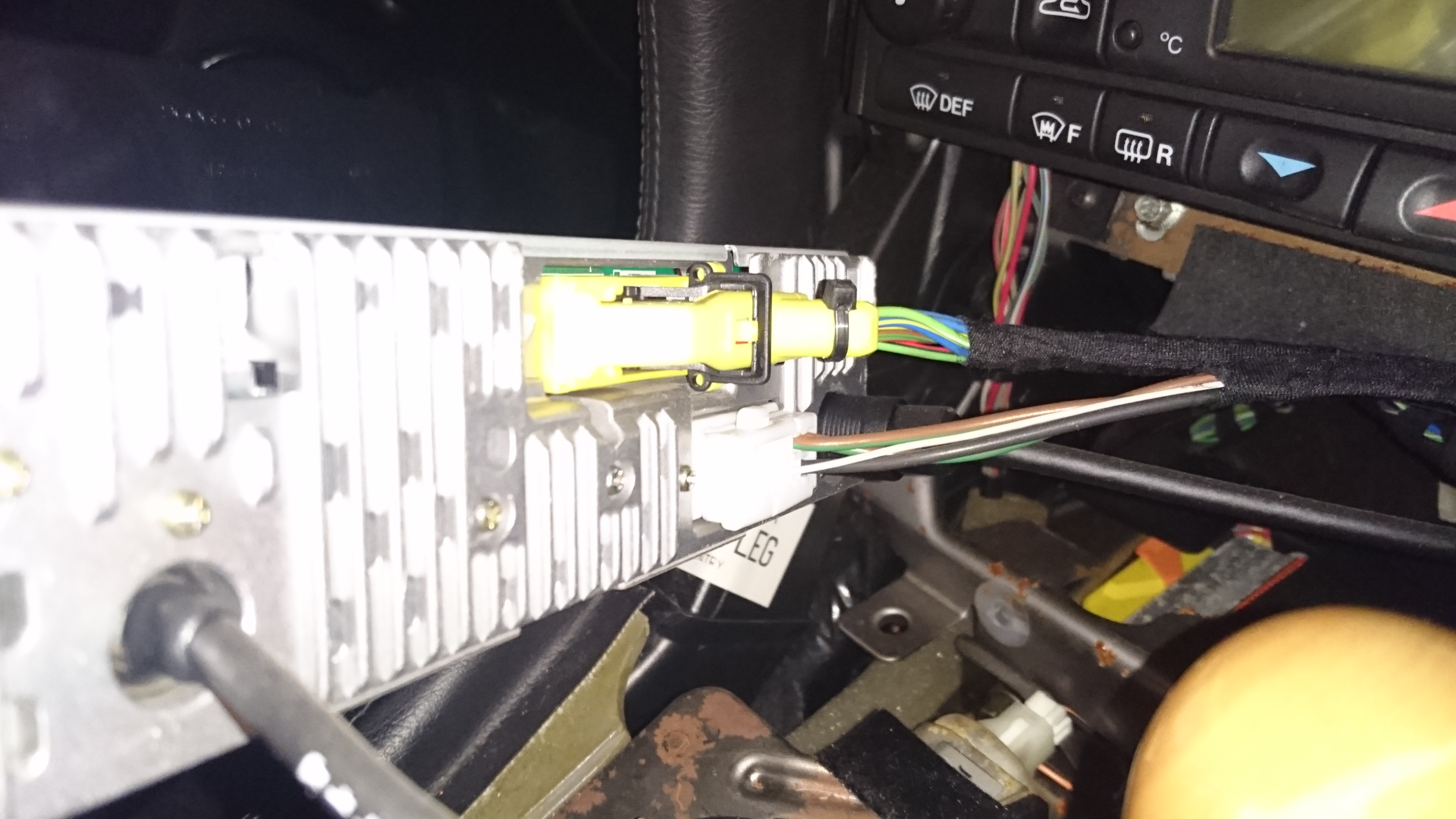
The head unit in light off Ebay had the white connector still attached with wires so I could see the pin out, the issue is that my wiring harness does not have several of the wires. I have attached a photo.
I used tape to separate the wires and this is not how it will be installed. My question is on my car are these wires not used or is there a different pin out for my car?
I plan on re-pinning the cables front and back and found a company that sells the pins for the connectors.
What a mess...
In your HK premium system, the head unit does not feed anything to the speakers, it sends a line level signal to the amp in the trunk which powers the speakers. I'd pull that side carpeting in the trunk to look at what's been done there at the amp as well. That jagrepair link will help a ton with clearing things up, make sure to get the 98 or 99 MY guides, since the others use the Alpine system which is wired slightly differently.
So if that's a connector formerly used off a basic x308 audio system, some of the wires/pins won't be used in your premium system. Compare the basic audio system (fig 16.1) and premium (16.2) IC10 connects to both 12v power and speakers in the basic system, while in premium only the power connections on IC10 are used and a different connector, IC34, sends the line level audio to the amp in the trunk.
First of all, thank you guys VERY VERY much for helping me solve this issue. I've been driving this car for several months with exposed wires.... it's not pretty!
I was sure that in my particular configuration the harness was only supplying power and you have confirmed that. The 6 pin gray din connector is supplying the audio feed to the power amp and the black din connector provides audio from the CD changer.
I looked at the wiring schematics (thanks for providing the link) but I am still not sure what order the wires go into the connector. I can see the differences on the premium spec and base spec. Maybe it's just my lack of experience reading schematics, I wish they had included the connector configuration. Is there a way to tell this from the schematic?
Also, I did pull the carpet in the truck and although they cut the connectors back there they left them so it's easy for me to just re-pin and reattach to the amp and sub woofer.
There should be a complimentary pinout info list for each wiring diagram that explains the connector types.
If you are reading the 98 electrical guide PDF, the one for 16.2 (premium audio) is on page 141. IC10 is a 20way multilock 070, IC30 is a 12way multilock. The connector images are on PDF pages 19 and 20. A few pages later there's some pin numbering diagrams, they don't include the radio but the numbering standard is the same way. Keep in mind the diagrams are showing module pins, if you're looking at the plug instead of the module the pins will be mirrored. I'd usually go by wiring color anyway if possible, as long as the pins haven't been removed and installed (which takes some know-how) they'll usually be in the right order.
After trying for weeks to find the correct factory pins for this 20 pin multi lock connector and failing, I decided to just go ahead and solder and shrink wrap the connectors in place.
I was able to find the correct multi lock connector for the head unit complete with cut off wires attached so I was able to salvage the pins. Even though the multi lock connector is correct, it was for the standard stereo and my car has the premium setup. I downloaded the electrical guide as you guys instructed, but I am not seeing the pin out for this 20 pin multi lock connector anywhere.
The trunk end of this 20 pin multi lock connector is in-tact. Does anyone know if the pin out on the trunk side matches the pin out of the dash side? If not, does anyone have the correct pin put for this multi lock connector, premium sound with 12 wires going to the multi lock?
I tried using a '98 electrical guide for mine, wasn't even close to the factory wiring colours, but managed to get a 2000 one.
Here's the Premium ICE wiring diagram for the 1998MY, you'll have to look up the Jaag colour codes for the wires, they're not obvious from the abbreviations....
I saw this diagram before but i think I am starting to understand what I need to do.... I'm just not used to reading schematics, but is this correct... the number after the IC10 corresponds to the pin location on the connector? so IC10-1 is pin 1, IC10-2 is pin 2 and so on? If this is the case, what's the best way to determine pin 1?
That's correct, IC is the harness name, for ICE, 10 is the connector name with the number being the pin on that connector.
My Big Yella, had the pin numbers on the outside of the casing so you know what went where (using the wiring diagram and cable colour).
Using the 2000MY wiring diagram I was able to connect my new radio's power aerial switch lead to the GB cable from pin 18, GB being the green cable with black stripe.
Sacrifices must be made for a noble cause . My 96 X300 had massive speaker rot that can be fully repair with the original speaker units very cheaply
yourself . Your 98 may or may not be in the same condition .
I am so frustrated with this I am about to go insane. I have messed with this going on 4 months now. I have followed these instructions to point but there is no clear indicator which is pin 1.
I have soldered everything back, the colors in the manual match exactly but
the pin locations for the connectors provided in the manual are all over the map and there is no mention of the connectors used for the stereo.
I don't want to short circuit the car. I took the pin out locations from a similar connector gong to the amp in the truck but that's not working on the head unit, no power. I simply need to know what they consider to be pin 1.
If I ever do get this working, I am starting to highly doubt it I will post detailed step by step with photos so that others won't have to go through this.
Does anyone know pin 1 on the connector that plugs into the stereo head unit?
I found an image I took from a connector that came with a head unit I purchased and it looks like I have the correct pin out, must be addition issues.
I'm going to have the same issue with this connector... I search everywhere to find the exact 5 pin DIN connector on the back of the head unit. I found it and will remove the wires and re-solder the wires from the car. I have no idea what the consider pin 1.
I found a head unit on ebay that has this connector attached and I bought it. I will just splice the cable.
Hopefully that's not the case but may very be. I still have hopes I will be able to get the sound system working again..... very frustrating path I've been down with this
Have you examined the DIN plug at the Amp/CD end to compare wiring colours?
I ditched all the Jaag plugs and most of the wiring when I installed my units.
Amp wired direct to battery using a fused powerline, bolted a negative to a ground pin in the boot.
Three pairs of cable from amp to head unit for front, rear and sub signal.
Power and earth from the white plug, soldered into new ISO plug to go straight into the HU's plug, and tapped into the yellow plug to trigger the aerial.
The CD/Amp signal and control cable is still in situ so the original units can be put back in, if need be.
The only trouble I really had was finding the speaker cables in the boot, after realising what all the plugs and cables in the dash did, and didn't do.
Best of luck with your far more complicated endeavour.
Thanks to everyone that helped with this issue and a special thanks to member lady-penelope. I completed restoring the factory sound system and everything works perfectly