
Instrument pack PIN Schematic x308


Thread Starter
|
Senior Member


Joined: Oct 2012
Posts: 310
Likes: 45
From: sydney
Can any one advise where the PIN SCHEMATIC is to be found for the 2 large pin connectors to the instrument pack for the x308 (1999)?
I am missing the green side light icon on the dash after doing a bulb replacement. I must trace the pin/wiring to see why it doesn't show up either when the car is initally started (when all the icons light up) nor when the side lights are activated (they come on as normal).
best regards
Pere
I am missing the green side light icon on the dash after doing a bulb replacement. I must trace the pin/wiring to see why it doesn't show up either when the car is initally started (when all the icons light up) nor when the side lights are activated (they come on as normal).
best regards
Pere
Veteran Member


Joined: Apr 2010
Posts: 7,657
Likes: 3,021
From: Arlington VA USA
Can any one advise where the PIN SCHEMATIC is to be found for the 2 large pin connectors to the instrument pack for the x308 (1999)?
I am missing the green side light icon on the dash after doing a bulb replacement. I must trace the pin/wiring to see why it doesn't show up either when the car is initally started (when all the icons light up) nor when the side lights are activated (they come on as normal).
best regards
Pere
I am missing the green side light icon on the dash after doing a bulb replacement. I must trace the pin/wiring to see why it doesn't show up either when the car is initally started (when all the icons light up) nor when the side lights are activated (they come on as normal).
best regards
Pere
The schematic and tracing wires will not help...the signal lamps in this module are all computer controlled by a microprocessor on the instrument cluster circuit board. You need to open it up and replace the bulb. It is socketed, so at least no soldering is involved.
Thread Starter
|
Senior Member
Joined: Oct 2012
Posts: 310
Likes: 45
From: sydney
Just to clarify, I am referring to the green icon , looks like 2 eyes with the eyebrows on the side instead of the tp. Its right next to the right hand indicator (Australia).
Are you saying that this is an LED bulb inside the circuit board? I replaced all the othe external wedge bulbs, 4 big 4 small which are socketed.
How do I open this cluster up. I took the back cover off and its all just a cuircuit board. I took the front cover off but it only reveals the dials and didn't go any further.
best regards
Peter
Thread Starter
|
Senior Member
Joined: Oct 2012
Posts: 310
Likes: 45
From: sydney
Heres a picture of the green icon on this webpage.. scroll down. The sidelights/parking lights, green icon looks like 2 eyes with eyebrows on the side.
Jaguar XJ8 instrument cluster Speedo (98 on). - Cluster Repairs UK
Can anyone advise or proved info on how to open it up to replace a supposed LED bulb inside?
regards
Peter
Jaguar XJ8 instrument cluster Speedo (98 on). - Cluster Repairs UK
Can anyone advise or proved info on how to open it up to replace a supposed LED bulb inside?
regards
Peter
Veteran Member
Joined: Apr 2012
Posts: 1,495
Likes: 220
From: Bairnsdale,Victoria Australia
No background illumination to LCD display. From your link Peter.
Does your dash light up during day time without turning on parkers/head lights ?
My speedo is so hard to read I'm thinking it might be,or it should be.
Does your dash light up during day time without turning on parkers/head lights ?
My speedo is so hard to read I'm thinking it might be,or it should be.
Thread Starter
|
Senior Member
Joined: Oct 2012
Posts: 310
Likes: 45
From: sydney
yes my dash lights up during day, without the parklights being turned on.
I think you need to replace one of the 4 big bulbs as I did. 2 were not working.
I think you need to replace one of the 4 big bulbs as I did. 2 were not working.
Trending Topics
Thread Starter
|
Senior Member
Joined: Oct 2012
Posts: 310
Likes: 45
From: sydney
Someone mentioned that there is an LED light for that green icon inside the circuit board. I have opened it up a little from the back, and peeked inside a little, I can see a few LED lights in there, but cant figure on how to separate the circuit board from the case. That LED must be dead and needs to be replaced.
Has anyone opened up the circuit board from the instrument cluster?
I note there are 4 x 10mm sized pin connectors on the upperside, then a red pin connector at the base. They look like they need to be disconnected to allow the cicuit board and case to separate. Then to replace that LED bulb.
Anyone have directions.
best regards
Peter
Veteran Member
Joined: Apr 2010
Posts: 7,657
Likes: 3,021
From: Arlington VA USA
Someone mentioned that there is an LED light for that green icon inside the circuit board. I have opened it up a little from the back, and peeked inside a little, I can see a few LED lights in there, but cant figure on how to separate the circuit board from the case. That LED must be dead and needs to be replaced.
Has anyone opened up the circuit board from the instrument cluster?
I note there are 4 x 10mm sized pin connectors on the upperside, then a red pin connector at the base. They look like they need to be disconnected to allow the cicuit board and case to separate. Then to replace that LED bulb.
Anyone have directions.
best regards
Peter
Has anyone opened up the circuit board from the instrument cluster?
I note there are 4 x 10mm sized pin connectors on the upperside, then a red pin connector at the base. They look like they need to be disconnected to allow the cicuit board and case to separate. Then to replace that LED bulb.
Anyone have directions.
best regards
Peter
To gain access, remove the rear white instrument cluster back cover screws and the cover itself. Then GENTLY unplug the four 4x10mm ribbon cable connectors at the top of the cluster (they pull straight out...you can grab them with pliers but do not sqeeeze too hard or the connector will be damaged) and the one red LCD connector a the bottom of the cluster. At this point you can lift the circuit board out of the case. To remove the bad bulb, simply pull it out of its socket. This is called a 'E73' bulb and is the smallest wedge type bulb made.
Last edited by WhiteXKR; Jan 17, 2014 at 07:52 AM.

Member
Joined: Oct 2012
Posts: 36
Likes: 1
From: Omaha, Nebraska
Ugh, tonight we attempted to replace the bulbs we thought had burned out in the Instrument Cluster only to find a Red broken wire which had come out of one the pins, along with a white wire that is attempting to eject also but still in the pin. The second problem is that there is no manual lever to adjust the steering column, which will not move either. Can anyone please tell us which pin the red wire goes to and whether or not the white wire will allow the steering column to function. Also, is this repairable or should a complete harness be purchased? Thank you in advance for your help and input.
Veteran Member
Joined: Apr 2010
Posts: 7,657
Likes: 3,021
From: Arlington VA USA
Ugh, tonight we attempted to replace the bulbs we thought had burned out in the Instrument Cluster only to find a Red broken wire which had come out of one the pins, along with a white wire that is attempting to eject also but still in the pin. The second problem is that there is no manual lever to adjust the steering column, which will not move either. Can anyone please tell us which pin the red wire goes to and whether or not the white wire will allow the steering column to function. Also, is this repairable or should a complete harness be purchased? Thank you in advance for your help and input.
See the attached document, steps 18 and 24 for pin position identification. The connector pins have locking tabs that may need to be gently bent outward to allow the pins to remain in place. If the locking tabs have broken off, contact me and I can make you a 'pigtail' with replacements pins to repair the harness for a nominal cost. Replacing the harness would be difficult and prohibitively expensive.
Member
Joined: Oct 2012
Posts: 36
Likes: 1
From: Omaha, Nebraska
Yes Sir, it appears to be a red wire with a dark (black) strip. I really could not see it very well as it is sitting in the garage with bad lighting but I will attach two photos of the wire which situated n the right side below the gages. This problem began right around the time I replaced the BCM however, since I am not much of a night driver, I had not noticed the Dash Gages nor anything else. I am a get in and start-her-up type of person but noticed that the Message Center was not working.
Again, thank you so very much for your prompt response and for helping in this situation. My friend is mechanical only (can remove and re-install things).
Again, thank you so very much for your prompt response and for helping in this situation. My friend is mechanical only (can remove and re-install things).
Veteran Member
Joined: Apr 2010
Posts: 7,657
Likes: 3,021
From: Arlington VA USA
Yes Sir, it appears to be a red wire with a dark (black) strip. I really could not see it very well as it is sitting in the garage with bad lighting but I will attach two photos of the wire which situated n the right side below the gages. This problem began right around the time I replaced the BCM however, since I am not much of a night driver, I had not noticed the Dash Gages nor anything else. I am a get in and start-her-up type of person but noticed that the Message Center was not working.
Again, thank you so very much for your prompt response and for helping in this situation. My friend is mechanical only (can remove and re-install things).
Again, thank you so very much for your prompt response and for helping in this situation. My friend is mechanical only (can remove and re-install things).
As for the steering tilt problem, check if fuse number 8 in the left rear fusebox is OK. If it is, try operating the tilt control repeatedly, sometimes they just have dirty contacts and if you start using it will begin to work.
Member
Joined: Oct 2012
Posts: 36
Likes: 1
From: Omaha, Nebraska
Sorry, those pictures are very out of focus and I cannot determine exactly the problem. There is not a red/black wire, but there is an orange/black wire on the right side of the gauge cluster. Could it be that? If position #7 is missing a wire, that would be it. That wire is the vehicle speed signal to the adaptive damping module. You might not even notice anything if that is the problem.
As for the steering tilt problem, check if fuse number 8 in the left rear fusebox is OK. If it is, try operating the tilt control repeatedly, sometimes they just have dirty contacts and if you start using it will begin to work.
As for the steering tilt problem, check if fuse number 8 in the left rear fusebox is OK. If it is, try operating the tilt control repeatedly, sometimes they just have dirty contacts and if you start using it will begin to work.
Veteran Member
Joined: Apr 2010
Posts: 7,657
Likes: 3,021
From: Arlington VA USA
Orange-purple is the low-coolant sensor signal. That is important to have but is not the cause of your other problems.
Is the message sensor not displaying messages or is the back light just out? If it is the backlight, there is a bulb right behind the display may need to be replaced.
If there are no messages at all, the LCD is probably bad.
Is the message sensor not displaying messages or is the back light just out? If it is the backlight, there is a bulb right behind the display may need to be replaced.
If there are no messages at all, the LCD is probably bad.
Veteran Member
Joined: Apr 2010
Posts: 7,657
Likes: 3,021
From: Arlington VA USA
Depends on the model year of your car. What year?
Also this would not be the first place to look for a problem of this sort...it would be at the coolant fill tank float or sensor in the tank.
Also this would not be the first place to look for a problem of this sort...it would be at the coolant fill tank float or sensor in the tank.
Last edited by WhiteXKR; Nov 23, 2014 at 06:13 PM.

Veteran Member
Joined: Aug 2010
Posts: 2,636
Likes: 1,636
From: Southington CT
Here you go:
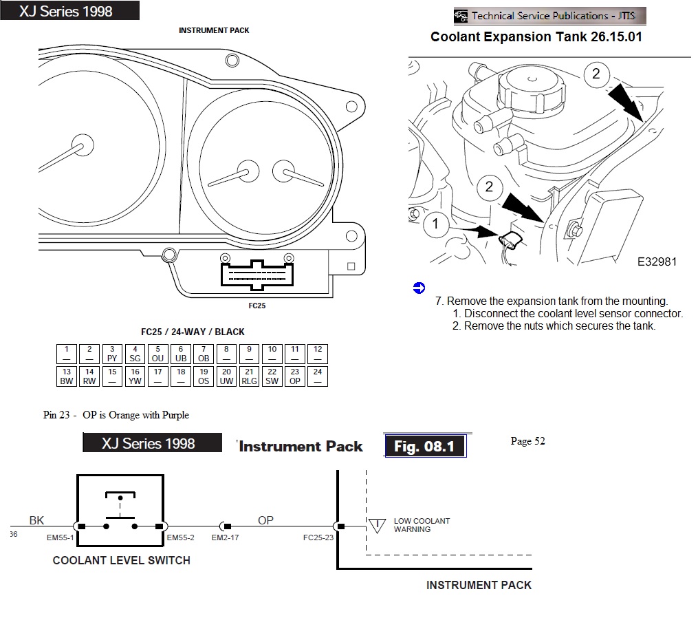
Also look at the following DIY on the coolant level sensor:
http://jagrepair.com/CoolantTankLevelTesting1999xk8.htm
Jim Lombardi
Also look at the following DIY on the coolant level sensor:
http://jagrepair.com/CoolantTankLevelTesting1999xk8.htm
Jim Lombardi
Last edited by jimlombardi; Nov 23, 2014 at 06:25 PM.
Veteran Member
Joined: Aug 2010
Posts: 2,636
Likes: 1,636
From: Southington CT
Note that there is a harness to harness connector in the wiring diagram (EM2 connector - OP wire location in that connector is pin #17)
Also here is the information on EM2 connector that is used for this harness to harness function:
EM2 is a 20-WAY MULTILOCK 070 / GREY - connector location is PASSENGER �A� POST / LOWER �A� POST FINISHER
Here is a JEPC showing the A-Post Finisher and its location
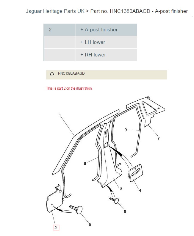
Here is more information on the lower portion of the A-Post Finisher.
You can see the Harness (that has the OP -orange purple wire) if you look under the passenger side of the dash just above the lower portion of A-Post Finisher.
If you need to look at the EM2 connector, it is the Finisher - Here is a photo that shows the Finisher's location:

Jim Lombardi
Also here is the information on EM2 connector that is used for this harness to harness function:
EM2 is a 20-WAY MULTILOCK 070 / GREY - connector location is PASSENGER �A� POST / LOWER �A� POST FINISHER
Here is a JEPC showing the A-Post Finisher and its location
Here is more information on the lower portion of the A-Post Finisher.
You can see the Harness (that has the OP -orange purple wire) if you look under the passenger side of the dash just above the lower portion of A-Post Finisher.
If you need to look at the EM2 connector, it is the Finisher - Here is a photo that shows the Finisher's location:
Jim Lombardi
Last edited by jimlombardi; Nov 24, 2014 at 04:43 PM.

Thread
Thread Starter
Forum
Replies
Last Post
DFW
F-Type ( X152 )
15
Oct 1, 2015 07:22 PM
Currently Active Users Viewing This Thread: 1 (0 members and 1 guests)