
Ignition Issue


Thread Starter
|
Junior Member
Joined: Sep 2011
Posts: 5
Likes: 0
From: uk
Hi,
This is my first post so I hope I am writing in the right section. There is a problem with my Car and was wondering if anyone can offer some troubleshooting suggestions;
Model: 3.6L XJ40, 1989
Symptom: Engine does not start, there is no spark at plugs when turning over engine, but there is a single spark (at whichever spark plug happens to be at TDC on compression stroke) when the ignition switch is turned
off (the engine was working fine a few weeks ago).
I have opened the wiring loom and checked it, it seems ok, I replaced the coil with a second hand one (which was working fine in another smaller car) but my Jag still had the same symptom.
I thought it may be either the Crankshaft sensor, the ECU or the Amplifier, I don�t know which would give this symptom (I also don�t know how to test these parts).
Appreciate if you can advise, thank you in advance.
Claire.
Senior Member
Joined: Apr 2011
Posts: 152
Likes: 43
From: Pennsylvania, USA
Hi Claire and welcome to the Forum.
It's Labor Day weekend here in the States, so attendance may be a little spotty.
1. I am not sure exactly what all the Inertia Switch kills when it's tripped (I'll have to do this on mine someday), but make sure yours hasn't been tripped.
2. I'll have to check, but I believe I have posted a wiring diagram (?MY) showing how the wires are connected and color codes for said wires.
wrong one, this is for a 1992 VDP
I'll get you a better one.
3. I would check all wires for tightness, first.
 Haynes-Roadside_Repairs.pdf
4. Haynes has some troubleshooting info on these components.

5. A test I would do to check the crankshaft sensor utilizes a voltmeter set on the AC scale. Get someone to crank the engine while you measure the voltage across the sensor's terminals. You most probably want to do this at the ECU. If the sensor is functioning, you should get an AC signal of voltage amplitude I'll have to check. No signal, and something is wrong.
I'll look for you a partial schematic that will help you.
o
It's Labor Day weekend here in the States, so attendance may be a little spotty.
1. I am not sure exactly what all the Inertia Switch kills when it's tripped (I'll have to do this on mine someday), but make sure yours hasn't been tripped.
2. I'll have to check, but I believe I have posted a wiring diagram (?MY) showing how the wires are connected and color codes for said wires.
wrong one, this is for a 1992 VDP
I'll get you a better one.
3. I would check all wires for tightness, first.
Haynes-Roadside_Repairs.pdf 4. Haynes has some troubleshooting info on these components.
5. A test I would do to check the crankshaft sensor utilizes a voltmeter set on the AC scale. Get someone to crank the engine while you measure the voltage across the sensor's terminals. You most probably want to do this at the ECU. If the sensor is functioning, you should get an AC signal of voltage amplitude I'll have to check. No signal, and something is wrong.
I'll look for you a partial schematic that will help you.
o
Senior Member
Joined: Apr 2011
Posts: 152
Likes: 43
From: Pennsylvania, USA
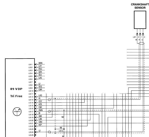
Please see attached schematic of wiring between the ECU and the crankshaft sensor for your car.
FYI:
So, what the above really means is to place your AC voltmeter probes on pins LI3-13 (Red wire) and LI3-24 (Blue wire) of your car's ECU, have someone crank your engine and you should get about 2.4 Volts AC.
If you switch your meter to DC volts, the voltage of pin 24 relative to your car's ground should be 0 VDC whether or not the engine is being cranked.
WARNING: do not crank the engine too long w/o a cooling off period.
o
FYI:
- the term, LI, stands for Lucas Injection harness.
- The sensor shield (W or white wire connected) is attached to chassis ground via LIS10. This attachment is not shown on this partial schematic.
Code:
   Pin     in/out           Circuit                 Active                 InActive
LI3-13   In (RED)   Crankshaft Sensor   PULSED SIGNAL: 2.4 VAC @ IDLE,        0V
                       ref. to Pin 24                   5 VAC @ 3000 RPM
LI3-24   In (BLUE)  Crankshaft Sensor              GROUND:0v              GROUND:0v
                       ref. to Pin 13
If you switch your meter to DC volts, the voltage of pin 24 relative to your car's ground should be 0 VDC whether or not the engine is being cranked.
WARNING: do not crank the engine too long w/o a cooling off period.
o
Last edited by Trick Freestones; Sep 5, 2011 at 02:23 PM.
Senior Member
Joined: Apr 2011
Posts: 152
Likes: 43
From: Pennsylvania, USA
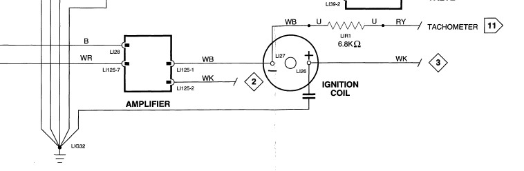
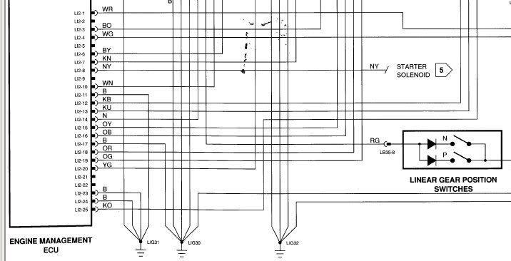
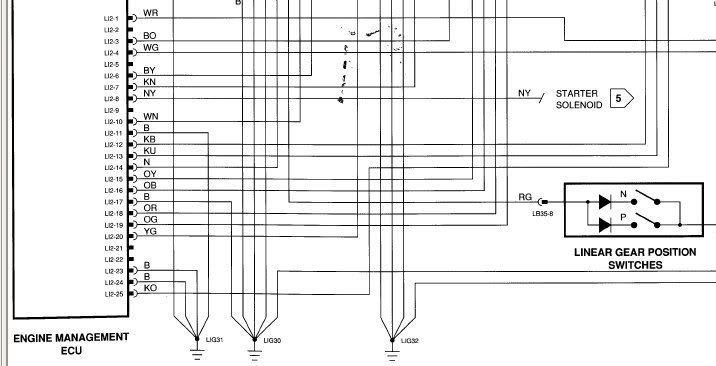
The following schematic is the wiring between the ECU and the ignition amplifier for your car. In order to make it legible, I had to split it in half.
Color codes for wires can be found on my thread, Jaɡ‧u‧ər Electrical Wiring Color Codes.
Some pointers:
explanation:
Color codes for wires can be found on my thread, Jaɡ‧u‧ər Electrical Wiring Color Codes.
Some pointers:
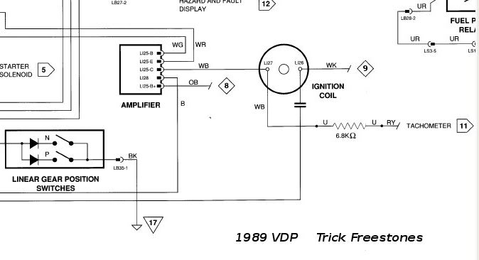
- Diamond shapes 8 and 9 are ignition switched power, so with key on you should "read" +12 VDC to ground with your voltmeter. If not you have a broken wire or connection problem somewhere.
- There appears to be a capacitor connected to ground at point LI26 on the Ignition Coil. If this cap "shorts", you will have NO voltage to the coil because it will be "shunted" to ground. If it is shorted you will probably see smoke as the wire insulation melts with the key on. If the cap is burnt open, it should be replaced.
- a WB (white with black tracer) wire connects the Amplifier (LI25-C) to the Coil (LI27). Ensure connections are tight.
- The Amplifier wire (LI28), which is colored B for Black, is connected to ground. Ensure it is a good ground.
- The wires, WR (white/red tracer) and WG (white/green tracer), connect from the Amplifier to the ECU at pins LI2-1 and LI2-4.
Code:
  Pin  in/out     Circuit                 Active                InActive
LI2-1 out ignition drive    pulsed signal         0V
                           approx 0.6V@idle
LI2-4 out ign amplifier      key on: 5V        key off: 0V
- With your voltmeter set to AC volts, you should get a 0.6V AC pulse with your probes placed on LI2-1 and ground while someone cranks the engine. No crank, 0V.
- With your voltmeter set to DC volts, the voltage measured at LI2-4 is 5V with the key on and 0V with the key off.

Member
Joined: Jun 2011
Posts: 80
Likes: 3
From: Tampa, Fl
OMG another Cap in a strange place.
Last time I saw a cap in an unexpected place was on te tail end of the auto trans on my old Volvo.
They get everywhere. But at least they are pennies to replace.
Interesting symptom though.
To get spark to one of the plugs...?
So that elliminates a lot of the switches and such. If its sending voltage to the coil, its trying to start.
Presumably, when you turn the key to "On" its priming the fuel pump too?.
I would suggest getting under it and smacking the starter with a heavy blunt object a few times. If that fails Test the starter directly, use another battery to test it, after unhooking it from the car of course.
Then if that doesnt work, start voltage testing from there backwards.
If you have a helper, great. If no, get a few bits of long wire and a 12v light bulb.

Junior Member
Joined: Aug 2011
Posts: 17
Likes: 0
From: San Diego
Claire,
I'm not saying it is not some sensor or something more exotic, but it just took me 6 months of searching for exotic things (see my thread called Mystery Stalling) only to find out my stalling / not starting issue on my 89 Vanden Plas was a problem in my distributor cap, rotor, plug wires (not sure which one it was cause I changed all three at the same time).
If you think about it, if you have spark from the primary coil, how is that getting to the spark plugs....it has to go through the coil wire, then through the rotor, cap and wires. If there is a problem with any of those..no start!
One note on the coil by the way: you mentioned you tried one from a smaller car....not sure that one will work. I tried a new coil that was for an XJ6 (instead of a Vanden Plas) and it "barely" ran the engine at idol. If I tried to increase the RPM, it just choked and coughed. The coil for the Vanden Plas definitely has way more juice.
Anyway, just something you may want to check. Good luck
Thread Starter
|
Junior Member
Joined: Sep 2011
Posts: 5
Likes: 0
From: uk
Hi, Sorry I have not been back to thank you for the advice, I have been running the checks.
Many thanks for your extremely professional advice and information on the problem I presented earlier, I would greatly appreciate if you could take a look at the data below which I have gathered during associated testing.
I have done the following checks on the crankshaft sensor electrical system that you have kindly advised and
have the following results, which I think make the ECU suspect, appreciate if you can give your professional
input / advice once again, thank you.
CRANKSHAFT SENSOR TESTS
Voltage measurements taken between the Red (L13-13) and Blue wires (L13-24),
Voltmeter Measurement: DC or AC Ignition Observed Voltage
DC Off 0.1
DC On 0.46
AC Off 0
AC On 0.02
AC Cranked 0
CRANKSHAFT SENSOR TESTS
Voltage measurements taken between the following wires on ECU and Ground (-ve terminal of battery connection)
Voltmeter Measurement: DC or AC Ignition Red
(L13-13) Blue
(L13-24) White
DC Off 1.36 1.36 0
DC On 7.66 8 0
AC Off 2.1 2.5 0
AC On 16.2 17.3 0
AC Cranked 14.2 15.2
Measurements on Red & Blue wires taken at ECU, Measurement on White wire taken at *front of engine.
The same readings were observed whether or not the *connector at the front of the cylinder head was connected
or disconnected (presumably eliminates the crankshaft sensor?).
(SUSPECT - FAULTY ECU)
CONTINUITY / SHORT CURCUIT CHECK (should be ok)
Continuity check along (the length of) and between (short circuit) wires:
Red Blue White
Red Yes No No
Blue Yes Yes
White Yes
Do you think it is the ECU?, if so any way to definitively test the ECU? - Before I order a replacement
(presumably repair is not an option).
Many Thanks again.
Claire.
Trending Topics
Thread Starter
|
Junior Member
Joined: Sep 2011
Posts: 5
Likes: 0
From: uk
The following schematic is the wiring between the ECU and the ignition amplifier for your car. In order to make it legible, I had to split it in half.

Color codes for wires can be found on my thread, Jaɡ‧u‧ər Electrical Wiring Color Codes.
Some pointers:
explanation:
Color codes for wires can be found on my thread, Jaɡ‧u‧ər Electrical Wiring Color Codes.
Some pointers:
- Diamond shapes 8 and 9 are ignition switched power, so with key on you should "read" +12 VDC to ground with your voltmeter. If not you have a broken wire or connection problem somewhere.
- There appears to be a capacitor connected to ground at point LI26 on the Ignition Coil. If this cap "shorts", you will have NO voltage to the coil because it will be "shunted" to ground. If it is shorted you will probably see smoke as the wire insulation melts with the key on. If the cap is burnt open, it should be replaced.
- a WB (white with black tracer) wire connects the Amplifier (LI25-C) to the Coil (LI27). Ensure connections are tight.
- The Amplifier wire (LI28), which is colored B for Black, is connected to ground. Ensure it is a good ground.
- The wires, WR (white/red tracer) and WG (white/green tracer), connect from the Amplifier to the ECU at pins LI2-1 and LI2-4.
Code:
  Pin  in/out     Circuit                 Active                InActive
LI2-1 out ignition drive    pulsed signal         0V
                           approx 0.6V@idle
LI2-4 out ign amplifier      key on: 5V        key off: 0V
- With your voltmeter set to AC volts, you should get a 0.6V AC pulse with your probes placed on LI2-1 and ground while someone cranks the engine. No crank, 0V.
- With your voltmeter set to DC volts, the voltage measured at LI2-4 is 5V with the key on and 0V with the key off.
The reply you sent to me was really impresive and I was wondering if you could offer any further experise to help me solve the matter.
I have posted the results of the tests I have run.
Can I also say thank you soo much for the visual aides, they helped greatly when I was working on the car.
Take Care.
Claire


Thread
Thread Starter
Forum
Replies
Last Post
FS[Western US]: XJS Lock Set with Keys- Doors, trunk, glove, gas, and ignition
XJsc-guy
PRIVATE For Sale / Trade or Buy Classifieds
6
Nov 23, 2015 01:56 PM
jagent
XJ6 & XJ12 Series I, II & III
10
Sep 12, 2015 01:40 AM
Currently Active Users Viewing This Thread: 1 (0 members and 1 guests)