When you click on links to various merchants on this site and make a purchase, this can result in this site earning a commission. Affiliate programs and affiliations include, but are not limited to, the eBay Partner Network.
I would remove the wire, earth that wire with the Ign ON, and the dash gauge should go full scale.
This eliminates the MOST common issue, as in the wire and the crimping at the connector.
The sender itself rarely fails, unless it gets clobbered by something and broken.
For $6 (its been a while since I needed one) I would replace the sender. Nothing special about it, same as a lot of period cars, Triumph, Rover, MG, etc etc.
I don't have it handy, but you can test the resistance pretty easy based on the specs in the service manual. I can look them up if you don't have access. Mine was acting odd, however, I agree with the above to just replace it. I did the temp sensor for the fuel injection at the same time.
Oh sorry, 1977 v12 euro spec.
on the right bank I see the sensor it has 2 wires.
i want to test the temp gauge so I guess I can ground any of the temp sensor wires and the gauge should go full hot ? I don�t want to mess up my gauge if I do something wrong�
thanks
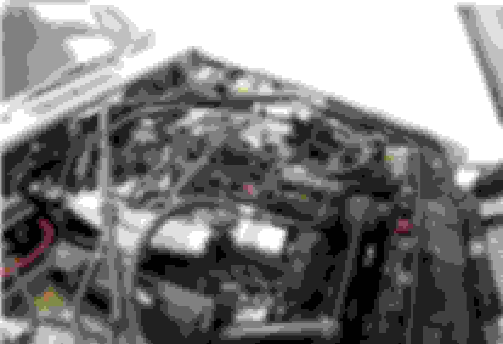
In your picture I see [what appears to be] a single wire sensor with a green wire, located on the RH water rail. The wire is probably green/blue, actually.
That looks like the sensor for the dashboard gauge.
If you ground that wire with the key on the gauge should go to max reading
Hard to tell in pic, but there are 2 wires…. I guess I’ll connect the 2 wires to bypass the sensor (low resistance) sending a hot engine signal to the gauge. I don’t know if a pure bypass will burn up the gauge. It is a bit corroded so I’ll clean it up today and redo the connections.
Last edited by Jeffkrell; Mar 2, 2024 at 12:22 PM.
I've been studying the 70s vintage parts catalogs. In the illustrations both a single-wire and double-wire sender are shown, depending on spec/market/engine number.
I don't know how the double-wire circuit works; it's not what I'm accustomed to seeing for the dashboard gauge. Maybe someone else knows or has a 70s vintage wiring diagram?
Is there a single-wire water temp sensor on the left side of the engine, by chance? If so, what is the wire color?
So it’s definitely 2 wires. I guess one is the ground. Uses a wire for ground instead of block. Plug was corroded. I cleaned and replaced the first 3 in of wires.
the issue is no power to the plug…. So I need to trace it to its source.
The sender I marked in red should be the sender for the dash gauge. As Doug says, the wire should be green with a blue stripe. The 2 wire sender is probably the temp sender for the EFI system.
So it�s definitely 2 wires. I guess one is the ground. Uses a wire for ground instead of block. Plug was corroded. I cleaned and replaced the first 3 in of wires.
the issue is no power to the plug�. So I need to trace it to its source.
For the temp gauge sender there is no power to the plug in the sense of "+" voltage. It's just a variable resistance to ground.
I'm not really convinced your on the right track with this two wire sensor but I'm not familiar with the early wiring configurations so I'm not on solid footing to actually assert otherwise
Ok. Now that I focused on the correct sensor the gauge works on the bypass test. So the sensor is bad. Bought 2 DAC2583.
2 for later modification to have 2 sensors on one gauge, switched. (A and B bank)