When you click on links to various merchants on this site and make a purchase, this can result in this site earning a commission. Affiliate programs and affiliations include, but are not limited to, the eBay Partner Network.
1990 Jaguar XJS - Ignition Module Air Gap for Cooling?
Hello Good People.
I'm wondering if folks would be willing to help me in my thinking (sometimes my ideas ain't the best, lol) about creating a bit cooler running situation for the two Marelli ignition amps that live on the top cover of the radiator plate/support at the front of the engine bay.
These amps are super expensive and hard to find. I got lucky the first time one went bad on me... I had previously purchased one (I had a permanent eBay search set up for them as they were/are posted) long before I needed it. Someone listed one for 30bucks NEW, and I snatched it up. Anyways,,,
The amps are affixed to two aluminum heat sinks and then, the way it was designed is that, the heat sinks are affixed to the top radiator mounting plate/support or what ever it's called at the front of the engine bay...? My idea is to first re-goop the amps with heat conducting thermal paste and then place one or two washers UNDER the heat sinks so their is an air gap between the sink and the radiator plate/support.
The thinking (where I usually get into trouble) is that the top plate/support of the radiator gets very hot itself and having the heat sinks being in direct contact with it (with no air gap in-between) must defeat the efficiency or the ability of the two aluminum plates to be as effective as dispersing the heat. At least a little bit... I figured the air would help??? What do y'all think?
Is there VALUE to heat and their function that I don't know about?
I'm also open to suggestions as to an alternative location... I really don't want to cut and resolder the wiring to lengthen for replacement to another location,,, but would consider it... To me, being mounted flush (like flush flush) to something that gets as hot as that plate - well, there has to be a better way.
Thermal compound would be a good idea between amp and plate, You could get a replacment plate that's an extruded heat sink (like from HeatSinkUSA) and re-drill it. It just has to be mounted and grounded.
As an aside, different amps have been discussed, and at least a generic one (that doesn't control dwell) is quite usable with a change of pinout.
Many years ago I put temperature sensors around the engine bay and checked the results.
The top of the radiator bracket is a hot spot.
Better to move the amps to be in the airstream entering the front of the radiator, that will be much cooler.
Thermal compound would be a good idea between amp and plate, You could get a replacment plate that's an extruded heat sink (like from HeatSinkUSA) and re-drill it. It just has to be mounted and grounded.
As an aside, different amps have been discussed, and at least a generic one (that doesn't control dwell) is quite usable with a change of pinout.
Hi Paul... Ok, I just read thru the thread linked and I hate to say that a lot of it went over my head. Square wave and dwell times etc...
What I am concerned about now when thinking of my "fix" is the idea that the plate and it's contact with the upper rad support provides the GROUND for the ignition amp? Is that correct? I did NOT know that...
I was considering using two fairly thick nylon washers (as nylon would conduct less heat than metal washers) to use as spacers which might negatively impact (no pun intended) grounding... I don't want to have decreased, inadequate or faulty path to ground and fry my amps.
And, if you would (or someone), from the thread info above or from any source, WHAT simple plug and play, or plug with a wire pin IN modifications (modest) would work for the 1990 XJS with Marelli amps?
I am also willing to hold off and look for 2 finned amps. I like the idea...
I'd be absolutely stunned - and disappointed - if it used that plate as a ground - very bad practice if it does.
If you want the absolute best heatsink replace the plate with a copper plate and clamp some copper heatsinks to that (don't look in the automotive arena go look in the PC and server cooling arena) - aluminium isn't even close to copper when it comes to removing heat. Like your original plan I'd be trying to isolate it from the radiator top bar.
You could mount something like this upside down and attach the amps opposite the fins - not sure how much space you have to play with though.
Great product...I like the idea... After reading folks input I was thinking something like that as well... Ok, I'm going to hold off a week until I take some measurements and have the plates like these, similar...
I also would be surprised if the ground relied on the contact between the amp, plate and rad cover. But I think I will wait for a definitive on that too.
Knowing about alternatives to these OE Marelli amps would help me sleep better at night as well...so, any info would be greatly appreciated.
I don't think it relies on the plate as a ground as much as the plate ALSO needs to be grounded. Pin #2 is ground on the Marelli amp:
But if you'll note (and I know they're different) the Lucas AB-14 amp works as ground and heat sink for the GM HEI Amp inside, which is grounded to that case via the bolt through.
Anyway, although that data is available for GM amp, I haven't "VERFIED" it for the 7 pin amp series, although construction & the heat sinking would suggest it would be good practice to follow keeping the heat sink plates at electrical ground as well.
Post#15 here describes what we did to get a BIM124 working as a substitute for the Marelli module. (Somewhere there's an old Facebook Group Thread where we worked it out... but I posted in the JaguarForums to preserve the knowledge). The main difference in the modules was the location of the pin, so it is possible to use a more generic module by using a pin removal tool on the Jag AMP harness side and simply move a pin over to a new location. That would be in a pinch though, as there does appear to be (as noted on the Jag-Lovers post) quite a number of direct cross numbers for the Marelli Amp.
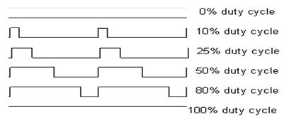
What I mean by square wave triggering. From the dinoplex.org site and conversations with Adrian who runs the site, the Marelli Microplex ECU controls amp modules by providing a ground for pin #3 of the Marelli module (Trigger Ground). The time the ECU holds it at ground = the dwell (duty cycle) time the ECU has decided to charge the coil. As soon as the ground is released (and voltage goes high), the ignition event is triggered. (This is an understanding from the Analogous Ferrari units). Again I haven't personally verified any of this. This is all via what I understood from conversations with Adrian.
Depending on the system, low or high, and/or a specific edge of the square (first or second) can be used for triggering. The image below shows going high to trigger and create the duty cycle for an event (like fuel injection). In the case of the Marelli amps I've been lead to believe the trigger is done by pulling the voltage (provided by the AMP itself) low.... I.e. the Marelli ECU does not provide a trigger voltage, but instead provides a trigger ground. And unlike a VR signal which creates an AC wave that a GM HEI amp has to use for a trigger, this is pretty much on or off.. so 1 or 0. Digital. (If you look through some of the documents on the other site you'll see different 7 pin amps expect different trigger types - like a VR trigger, or Hall Effect trigger (digital on/off). )
~Paul K.
Last edited by FerrariGuy; Jul 9, 2022 at 10:32 PM.
Many years ago I put temperature sensors around the engine bay and checked the results.
The top of the radiator bracket is a hot spot.
Better to move the amps to be in the airstream entering the front of the radiator, that will be much cooler.
I like the idea but worry about water. Somehow I missed this post and wanted to respond... But yes, of all places. The top of the radiator is a hot spot. I drove yesterday, about 20miles, opened the hood to just get a temperature feel and I couldn't keep my finger on the screw/bolt that fixes the amp to the plate. Not for more than a second, it was that hot. Can't be good.
Now I'm going to TRY and reply to Ferrari Guys post. Some folks is jus too dangGone smart, 🤣
I don't think it relies on the plate as a ground as much as the plate ALSO needs to be grounded. Pin #2 is ground on the Marelli amp:
But if you'll note (and I know they're different) the Lucas AB-14 amp works as ground and heat sink for the GM HEI Amp inside, which is grounded to that case via the bolt through.
Anyway, although that data is available for GM amp, I haven't "VERFIED" it for the 7 pin amp series, although construction & the heat sinking would suggest it would be good practice to follow keeping the heat sink plates at electrical ground as well.
Post#15 here describes what we did to get a BIM124 working as a substitute for the Marelli module. (Somewhere there's an old Facebook Group Thread where we worked it out... but I posted in the JaguarForums to preserve the knowledge). The main difference in the modules was the location of the pin, so it is possible to use a more generic module by using a pin removal tool on the Jag AMP harness side and simply move a pin over to a new location. That would be in a pinch though, as there does appear to be (as noted on the Jag-Lovers post) quite a number of direct cross numbers for the Marelli Amp.
What I mean by square wave triggering. From the dinoplex.org site and conversations with Adrian who runs the site, the Marelli Microplex ECU controls amp modules by providing a ground for pin #3 of the Marelli module (Trigger Ground). The time the ECU holds it at ground = the dwell (duty cycle) time the ECU has decided to charge the coil. As soon as the ground is released (and voltage goes high), the ignition event is triggered. (This is an understanding from the Analogous Ferrari units). Again I haven't personally verified any of this. This is all via what I understood from conversations with Adrian.
Depending on the system, low or high, and/or a specific edge of the square (first or second) can be used for triggering. The image below shows going high to trigger and create the duty cycle for an event (like fuel injection). In the case of the Marelli amps I've been lead to believe the trigger is done by pulling the voltage (provided by the AMP itself) low.... I.e. the Marelli ECU does not provide a trigger voltage, but instead provides a trigger ground. And unlike a VR signal which creates an AC wave that a GM HEI amp has to use for a trigger, this is pretty much on or off.. so 1 or 0. Digital. (If you look through some of the documents on the other site you'll see different 7 pin amps expect different trigger types - like a VR trigger, or Hall Effect trigger (digital on/off). )
~Paul K.
So,,, yup. I'm going to stay away from all of this technical stuff FG, and spare myself sounding like the dumb ***. I've been trying to digest what you're saying here and some of it makes sense, rough concept... I think I will leave it there for now until I get a chance to start looking around the web for additional info,,, with your info as the spark and base for how I even begin searching. Still, I think im getting the general idea.
For now what I got,,, or may have. Additional/redundant grounding of the new finned plate and the amps connection to it will actually not be too hard. And from your pin out imagine above I can't see why adding a dedicated additional around to pin 2 (the wire itself, with a soldered wire tied into it to chassis ground?) would be a BAD idea, unless you all said it is not. Grounding on the XJS is always suspect. I don't even know where pin2 grounds live after leaving the amp.
Is the PIN 2 ground just a chasis ground somewhere,,, or is there something more going on?
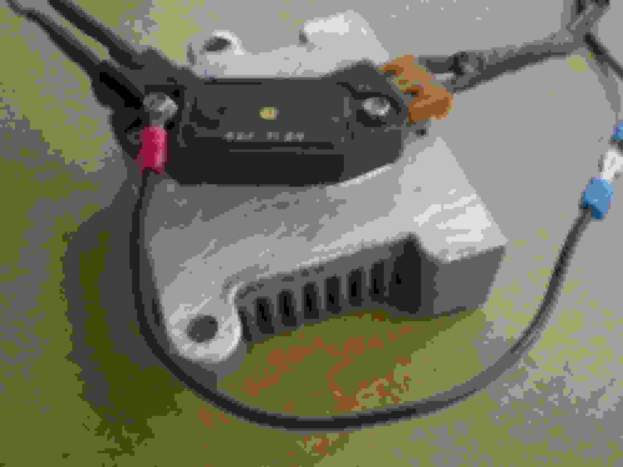
This is what I have so far. This plate, paste - nuts and bolts, lengths of wire to ground things, to next on the list. I leaned against copper for aluminum.
I think I may actually TRY and cut some threads into the new plate pin down the amps... Never done that kinda thing before.
This is the DEPTH I'll have to work with. Top O the rad plate to roughly the top ridge of the bonnet to rad plate rubber seal...
Last edited by JayJagJay; Jul 11, 2022 at 06:39 AM.
Put some 'Play Dough' on Top of those Ignition Amplifiers, Then Close the Bonnet/Hood then when you open it again, you will see just how much Space you haven't got!
And from your pin out imagine above I can't see why adding a dedicated additional around to pin 2 (the wire itself, with a soldered wire tied into it to chassis ground?) would be a BAD idea, unless you all said it is not. Grounding on the XJS is always suspect. I don't even know where pin2 grounds live after leaving the amp.
Is the PIN 2 ground just a chasis ground somewhere,,, or is there something more going on?
Well... sort of. Technically there can be different grounds, like ECU ground for it's +5V output to make measurements (like through the CTS) etc. But in practice they all end up at body ground. You don't need to worry about Pin 2 itself as that already has a wire to ground in the harness itself. You only need to make sure the cooling plate isn't isolated from the body via some sort of plastic stand off. The screws going through the Amp fastening it to the plate will make the electrical contact between the Amp and HeatSink, and THEN you only need to either make sure the fasteners through the heat sink to the body are conductive, or add a small ground jumper between plate and body if you put the heat sink on some sort of plastic stand off. That's all. Pretty straight forward.
Put some 'Play Dough' on Top of those Ignition Amplifiers, Then Close the Bonnet/Hood then when you open it again, you will see just how much Space you haven't got!
Now where O where did I put that damn play dough, 😆
I got ya. I measured a good 50mm + so I should be alright clearance wise, I think...
And yes FG... I will mount the finned plates directly to the rad cover like they are/were, then put together some wires and eyelets and sandwich them in when I bolt things down and attach to chassis firmly... Thanks for all your help and HOPEFULLY someone will read this thread down the line and ALL the science you DROPPED will be snatched up and used. I appreciate you offering all that knowledge up! Really! I'm just not the guy, lol
I would advise against putting the heatsinks against the radiator top brace - go with your plan and leave a gap - you want to remove heat from the amps not from the radiator brace so you want as little in contact with that as possible - worst case get some of that stick on heat shield.
whilst this is difficult to explain the back of the amp has a metal plate - not the large aluminium thing that they are mounted on. This plate is provided for heat transfer and should not need to be grounded. Some of these amps though do require that at least one of the bolts on each amp to be - there should be a copper or metal 'via' or sleeve through the mounting holes in this FG is totally correct, if there is no such metal sleeve in the mounting holes then grounding is not necessary.
This could be 100% proven but you would need a decent multimeter to do so - at least 20 Mohm input impedence or you risk doing damage, if you have such a thing then when you have the amp removed from the car check each pin to the plate on its base - there should be no connectivity at all. One oor more pins 'may' register to any of the copper via's or sleeves present but it shouldn't be a dead short.
I believe (I could go back and look) that the finned heat sinks I'll receive are 25mm thick. I plan on bolting them fins down, flat side on top, amps bolted to the flat on top... 25mm off the rad cover with air and fins in between... I'll insure ground with a ground strap, basically a wire with crimped loops screwed or bolted down on the rad cover, or somewhere else on the chassis... In my mind this is quite a bit better and will deal with heat better than the OE setup...? No?
Absolutely - and that is exactly how I'd mount them - fins down and I'd insulate the fins from the metal of the top brace - but even fins in contact is better than OE