Cruise Control issue in '88 XJS V12
#1
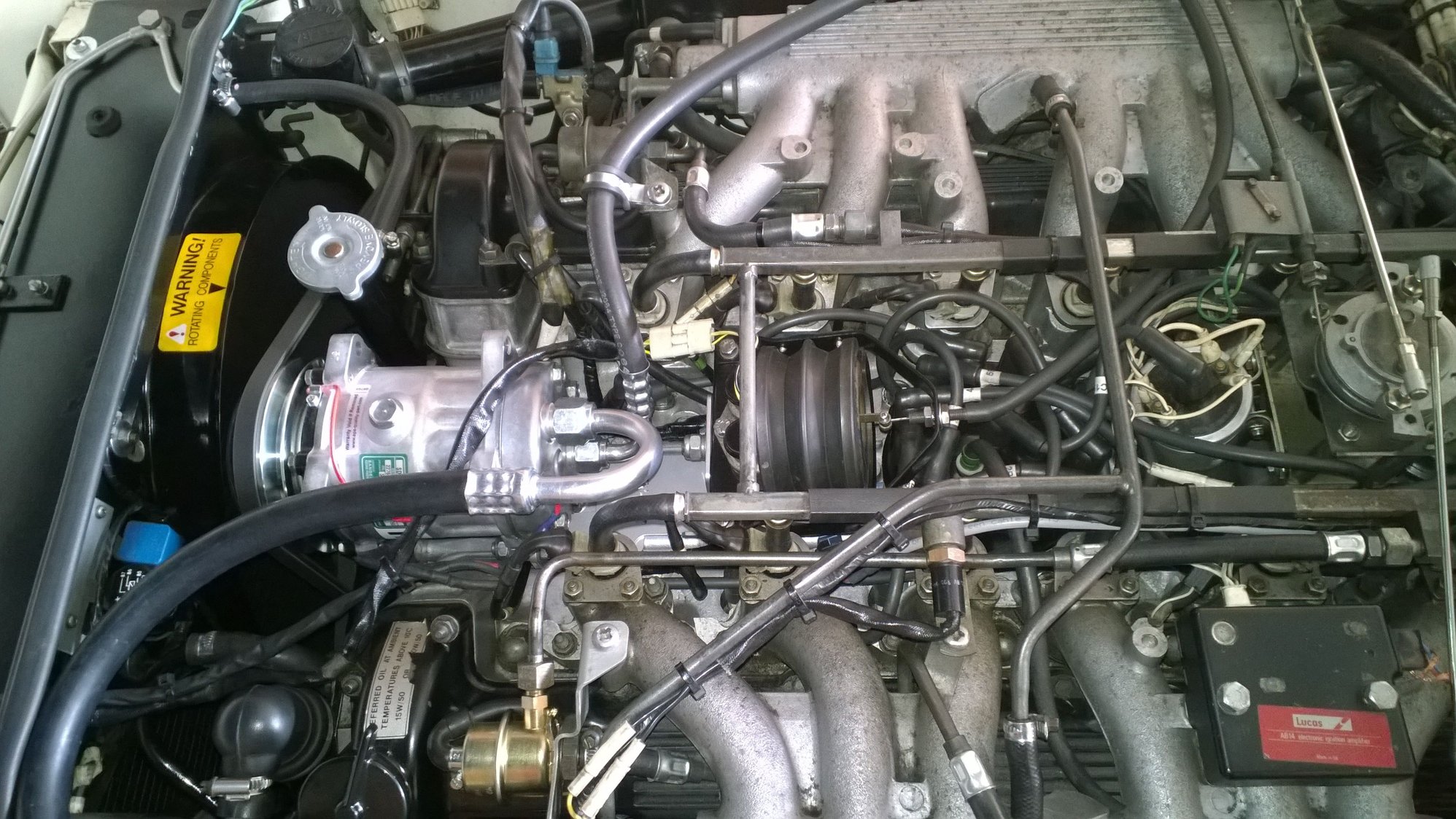
When I bought my '88 XJS back in February the previous owner had the entire AC system rebuilt, including the new compressor. However, my cruise control system has never worked. I discovered that whoever replaced the A/C compressor failed to ever bolt the CC bellows unit back on to the rear of the A/C compressor. I found the bellows lying in the center of the engine behind the compressor with only the accelerator cable hooked up to it I now have it bolted back in place but the vacuum port on the top of the bellows body has the fuel rail crossover tube jammed up against the port making it near impossible to shove my vacuum line on to this fitting. Does anyone on here know what I'm doing wrong? It appears that if I could mover the entire fuel rail forward about 1/8" then I would be able to put the hose on this fitting. Something is wrong so any help here would be appreciated. ..................Mike..
#3
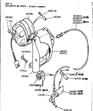
I'll take some pix tonight and post tomorrow, but I'd bet that is the problem. I have no idea at this point if it is upside down because it was just lying in the center of the engine and I just bolted it to where it seemed to fit. Is it possible that the steel bracket was bolted to the back of A/C upside down? That steel bracket has 2 bolts holding it to the compressor but the center bolt has a threaded hole that appears to only be able to hold the bellows on the top side which may be upside down Currently the plastic shield cover is on the top side, not the bottom, so maybe the A/C service people accidentally put it in upside down and left the bellows lying there.because they couldn't figure out how to hook it all up. Wow, this gives me some hope. I'll let you know.
Also, does the accelerator cable jacket nut have the other nut jammed up against on the other side of the bracket? The second nut appears to just be a locking nut (on mine it's loose) but perhaps there is an adjustment of them that would set the distance or where the cable jacket needs to be in relation to where the cable coupling is at the bellows. . ....................Thanks! ...Mike.
Also, does the accelerator cable jacket nut have the other nut jammed up against on the other side of the bracket? The second nut appears to just be a locking nut (on mine it's loose) but perhaps there is an adjustment of them that would set the distance or where the cable jacket needs to be in relation to where the cable coupling is at the bellows. . ....................Thanks! ...Mike.
#4

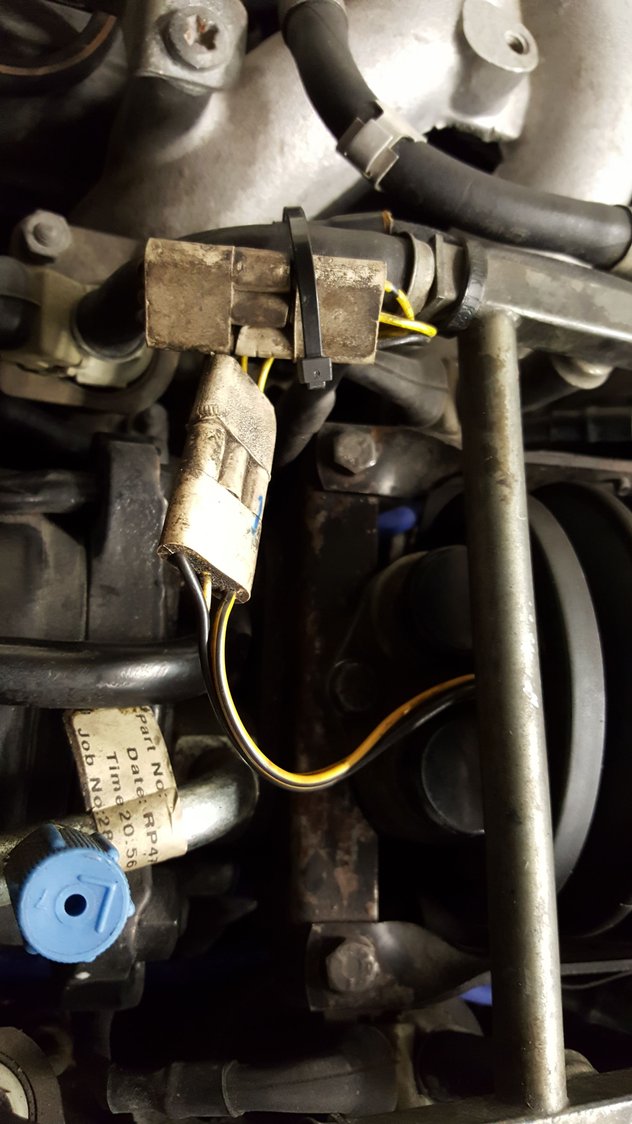
Hopefully these pictures show it all clearly enough. The curved "cover" is the heat shield so it goes between the "heat" i.e. the engine and the bellows to protect the rubber. The two short bolts hold the bracket. The long bolt goes through the block that holds the solenoids, with the vacuum attachment underneath.
#5
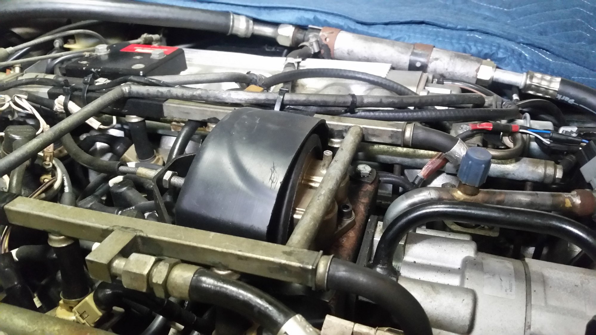
CC currently installed upside down. The reason I installed it this way is because it was lying in the engine in this position. Oh well, dumb me!!
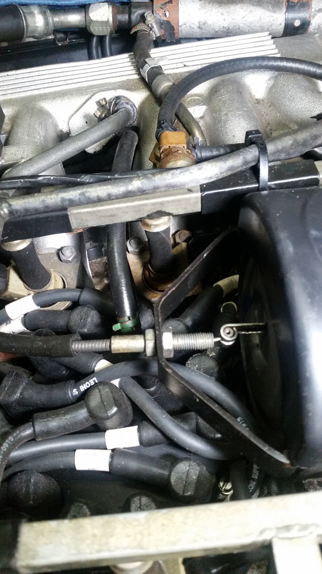
Is there an adjustment that needs to be made to these 2 nuts to calibrate the cable sheath distance from the bellows?
I went home at lunch today to check it out. Yes, the whole bellows unit and shield are upside down because all I did was take the upside down unit as it lay in the engine and moved it to the top where it would bolt to the bracket. I guess the steel bracket that bolts to the back of the compressor is in the correct position and all I have to do is turn the CC unit and shield upside down. Looks like I need to go ahead and install my new vacuum hose to it before I bolt it back in because once it's out of sight I won't be able to get to it. I guess there is a relay and connector for it down below because I currently don't see it on the top and that once I have it turned back correctly I should see it. Is that right.
Also attached is a pix of the accelerator cable attached to the bellows. Is there any adjustment to the 2 nuts other than locking them tight against each other? Hey guys, once again, thanks for all the superb help on this big puzzle. Gotta admit it's fun, though.
#7
Trending Topics
#8
Yeah, that's right. Close counts if you're working on the system, as long as it's not pulling the throttle open when disengaged. I made this the final adjustment once I got it all working properly. If you end up having to replace the cooked bellows (that cracked from heat) you'll be doing it all again.
#10
Wow, that makes sense. It looked to me like heat would have attacked the plastic cover but it looks like it probably takes care of both issues when it's underneath the bellows. Either way I have it upside down and need to get it mounted correctly. In the process of mounting it incorrectly I did feel the bellows and the rubber felt soft and supple but I'll give it a visual when I rotate it properly.
#11
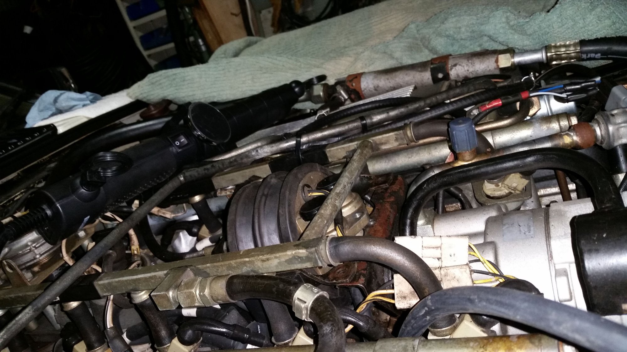
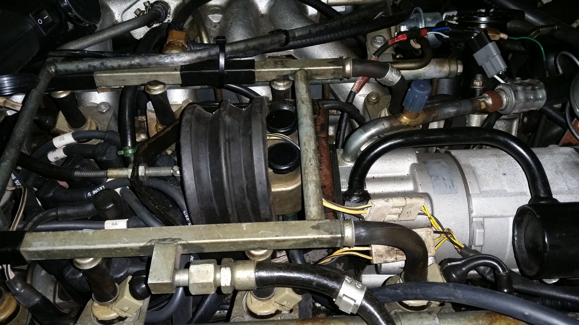
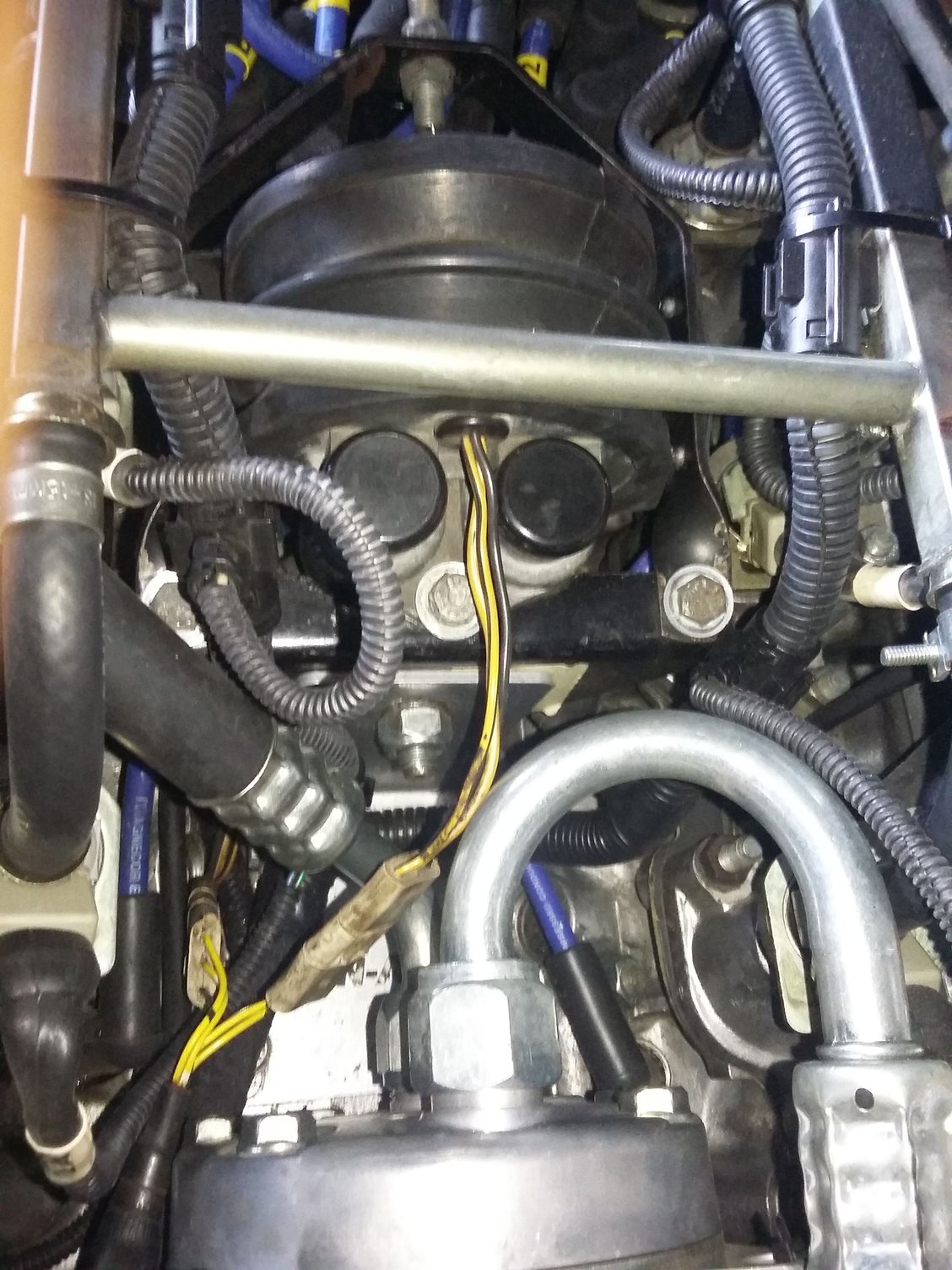
I think I've beat this subject to death, I need one more clarification, ......that of the steel mounting bracket as in these 2 pix on my car. Did the previous owner also mount the steel mounting bracket upside down, the bracket that is bolted to the back of the the compressor. I turned the speed control bellows to the proper position (it was upside down) but it looks like it still won't clear the cross fuel rail. If my bracket is upside down then it appears that I would have to remove the steel bracket from the back of the compressor (2 bolts??), invert it and then somehow bolt it to the speed control first, and then bolt it back to the compressor? I've attached some pix showing the position that my steel bracket is currently in and my speed control unit just sitting on the steel bracket yet not clearing the fuel cross rail. If I need to invert the steel bracket then do I need to support the back of the compressor because it supports the compressor as well as the speed control unit? Thanks for all the help........... Mike.
#12
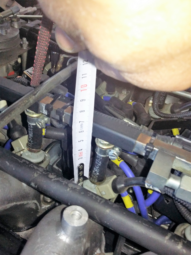
Well it doesn't "look" upside down. I measured mine. The top of the fuel cross rail sits about 2.5 inches above the top of the bracket. Your bracket looks like it's all sitting a bit high for some reason. I've not dug into mine as far as you might have to so can't help much there. I can tell you that the bracket can stay in place when you remove the bellows and solenoids so you should be able to bolt it to the compressor or wherever it belongs and then bolt the CC unit on afterwards.
The following users liked this post:
51rover (10-01-2018)
#13
Yes, that's my confusion here. I wouldn't know how to get to the bolts that hold the compressor to the bracket if the speed control was in the way. What I have here seems to be the correct orientation of the bracket so that the Speed control will mount on top of the bracket. I wonder if the bracket is bolted to the rear compressor mounting holes in the wrong location, Perhaps a pair of bolt holes on the compressor are beneath where the bracket is currently mounted, which would make the bracket be down lower when used.
#15
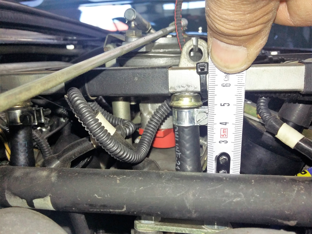
Yes, I went home at lunch to measure the distance from my fuel rail top to the top of the mount plate and measured 1 1/2 inches, about 1 inch higher than your correctly mounted speed control bracket at 2 1/2 inches so mine is too high. I lifted the entire speed control unit up out of the way and find that only one large bolt on the steel bracket holds it in place. Believe it or not, that bolt is the same bolt that holds the AC compressor's inlet/outlet refrigerant coupling in compression to the compressor's body. To If I loosen that bolt, all the refrigerant will leak out making me have to re-charge the whole system. So, it looks like I will have to figure out some way to lower the Speed control body with spacers below the mounting bracket. I'll have to drill out the threaded nuts on each side of the bracket for clearance and tack weld a couple of new nuts to the the bottom of the steel yoke holding the bellows so it will work with spacers and still bolt down from the top side of the original bracket. Yikes, what a messy challenge. .
#17
I wish mine was like yours is so I didn't have to deal with this issue. My XJS is a 1988 version but not sure what yours is. Your fuel rail cross tube is considerably higher above the steel mount plate on your model year car or someone retrofitted a significantly different AC compressor (R134) that is higher on the engine of my car, making the space on mine at least 1" closer to the plate. And the solenoids of the CC will not fit under the fuel cross rail while sitting on top of the mount plate. Thanks for your input to a rather messy situation on my end. Looks like I'll have m work cut out for me this weekend when I tackle this job while not removing my mount plate, thus not opening up my refrigerant gas line. ................Mike.
#19
That gives me something good to do a lunchtime today. I'll measure from the top of the fuel rail to the top part of the injector and get back. I also posted in one of my earlier posts here that my fuel rail distance from the top of the CC mounting plate is 2 1/2" to the bottom of my fuel rail instead of the top of my fuel rail. I'll get that number again too so perhaps I can verify what I have here. If the shorter injector hoses are installed here, making the rail closer to the bracket, then that would at least explain what's happened but would make me still have to build an adapter to remount the CC lower.
I will be back here and post once I get that info later today. THANKS! .............Mike.
I will be back here and post once I get that info later today. THANKS! .............Mike.


