When you click on links to various merchants on this site and make a purchase, this can result in this site earning a commission. Affiliate programs and affiliations include, but are not limited to, the eBay Partner Network.
For those considering removing the XJS steering column to repair the horn circuit, I thought it would be better to just start a new thread to show the pix of what the internal parts look like when totally disassembled. I've been careful to take it apart so it can be kept original (if I decide to) without damage to the individual parts. What follows is what you will see as the upper column is taken apart for the horn circuit.
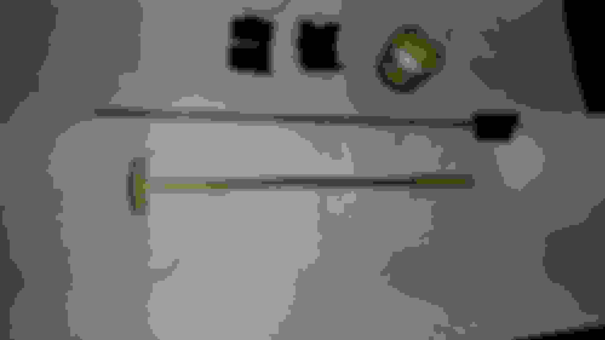
This pix was taken so one could see that the triangular centering plastic piece looks like. It holds the pointed rod right under the slip ring on the column interior.
Look close at about the center of the pointed rod above that slips inside the horn button tube, making contact with the wiper slip contact on the end of the right lower hollow tube. Left end is the actual horn contact button under the steering wheel pad. This allows the steering wheel to telescope in and out, maintaining continuous electrical contact down to the slip ring wiper of the horn "feed" wire. In the middle of the upper rod you can see there is corrosion making my horn not work.
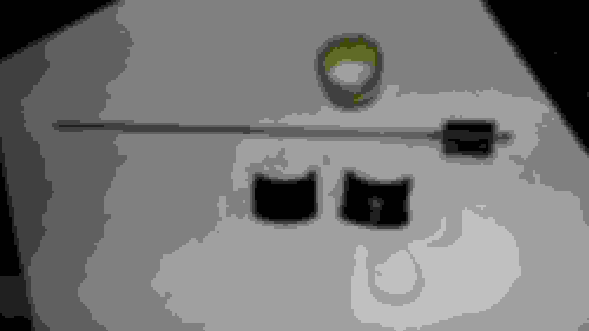
A better pix of the interior horn rod.
Horn electrical assembly
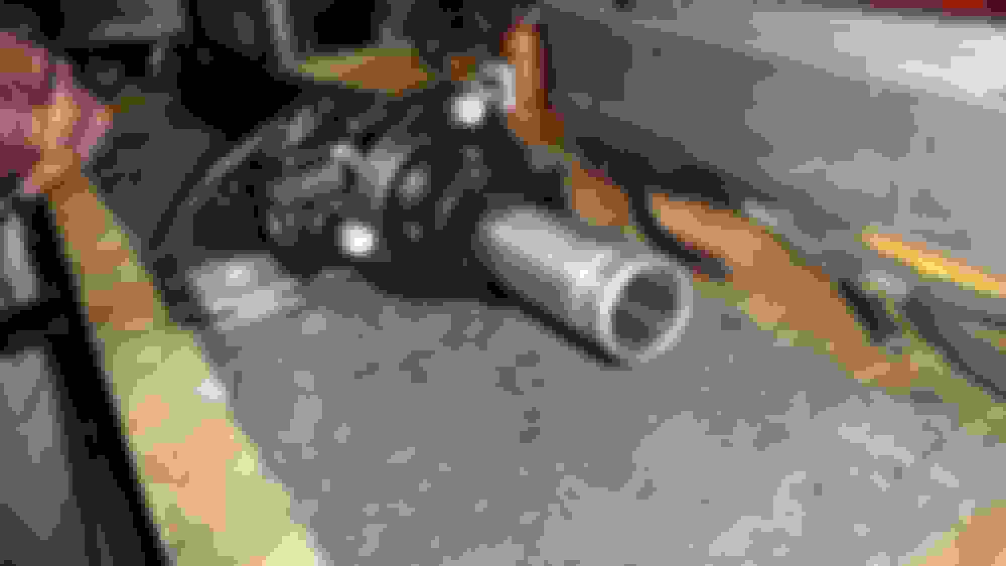
Steering shaft stripped of the electrics. Hole is where the black plastic insulator halve go.
Headless bolt removal with pointed chisel. see the thread locker glue.
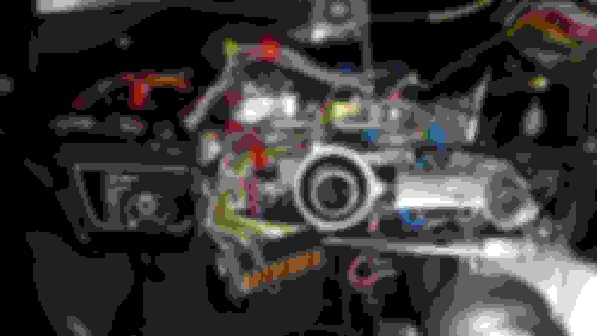
Slip rings on column with contact wipers removed. Left is "+ lead from horn relay, that connects to the horn button through the interior column telescoping brass rod contacts. Right is ground contact.
Pointed end of brass rod that connects with horn button tube.
Ignition switch on the right side was removed column was column was out. This makes an already difficult task of removing the 2 theft proof headless bolts much easier. Both bolts had thread lock compound making the job a pain.
This best shows the insulator ring halves together. The extension of the left half goes down in the hole of the column to provide insulated contact thru the column for the spring that contacts the ring to the interior brass rod. Be careful removing it.
Rebuilt ring installed. I would suggest putting a small bit of high quality non-conductive sealant (I used Dow-Corning clear Sealant) at several places on each side of the brass ring to help minimize any lateral movement.
What the top end of the column looked like during assembly.
I sacrificed my horn button tube to put a button disconnect at the top so I can remove my steering wheel if need be. I tapped an 8-32 thread in the banana plug and button tube for a brass stud, then soldered it all, then heat shrink it. Soldered the red jack on the column wire with heat shrink.
Final product ready for installation after the steering wheel is back on the column. Heat shrink the red jack to wire. Though probably not necessary you can heat shrink the 2 together just prior to final install.
Now I'm in the column horn part assembly mode. I drilled a small hole in the now removed brass contact ring for the horn "lead", just big enough for my small multi-strand teflon coated wire to pass through. I soldered the wire (stripped insulation about 1/8”) on the top side of the brass contact ring, taking care to flatten out the fine stranded wire on the ring beforehand so it won't come too close to the inside of the column when soldered. Be sure to "tin" the ring in the area you intend to solder. Note: The type of wire you use is up to you. I took in to consideration that all this horn wire inside the column does is take 12 or 13 volts supplied through it and ground it at the column top and the current load is very small. I measured the current to be .130 amps at 13.6 Volts. The wire length will be no more that about 18”-24”, depending on how much slack you coil up in the column. So I used a very fine stranded (very flexible) 28 gauge wire. The following assembly order is what I used to put it all together:
1. Take the contact ring with the soldered wire and thread the black plastic insulator half (has hole in it) with the wire you chose to go up the column. Thread the wire all the way through that half until you can put that insulator half with the hole up inside your contact ring. At this point you'll be holding the ring in your hand with half the black insulator installed in it, along with the excess wire hanging out that you'll run up the inside of the column in a few minutes.
2. Pull the insulator back out of the brass ring so you can now install both insulator halves together complete inside the brass ring.
3. Now comes the fun. Thread your wire up through the hole in the side of the column and shove it up the column until it comes out the top. Make sure your wire has plenty of excess that you can cut off later.
4. Slide the ring over the lower part of the column and up near the installation point, pulling the slack out of the wire that is coming out the column top as you slide the brass ring almost in to place. Once there you can install the insulator into the column hole so that the wire on the ring goes down through the insulated hole and out the column top.
5. Install the other half of the insulator noting that the groove on one side of the insulator faces the bottom end of the column. It should be obvious that the contact ring fingers face the bottom end as well.
6. This last step is definitely a challenge. You'll be sliding your ring over the 2 insulator halves that now have a soldered wire to the ring, making it a tight fit (tight is good). I actually took a blunt chisel and pushed somewhat of a small dent in the plastic insulator top to allow my soldered wire to sit in. I then pushed it on all the way, tight all the way, until the fingers on the contact ring snapped in place on the black insulator ring groove. Be sure that while you are sliding the ring into place that you are also gently pulling out any slack wire at the column top at the same time. That’s it! You should now be looking at what the Factory should have done without all that mechanical connection stuff inside the column. I modified my old horn nylon nut to connect my wire to at the top of the column by cutting off most of the brass tube, threading a 10-32 stud into the tapped brass tube and a banana plug. See more pix below. My rebuild was a a bit different that Warrjon's because I managed to save my original main parts during disassembly. I actually only trashed the little compression spring that's down inside the black plastic insulator hole. It wouldn't come out (stuck) so I just took my needle nose pliers, held a firm finger on each side of the black insulator hole and stretched it beyond recognition out of the hole without hurting the black insulator. Getting the black insulator out of the hole without damage was a bit of a challenge but removing the other half of the insulator gave me a chance to slightly, slowly, carefully lift up each end (not much) and twist back an forth while I barely lifted up on it and I found that it just popped up out of the column hole without damage. If successful, you won't have to build new parts for the rest of the repair.
I would like to thank Warrjon, Doug, V1rok and the others on this forum that helped me figure all this out. Hopefully, the next person will have an easier time with this challenge.
Jaguar used to sell the parts (back in the 1980s) to rebuild the horn parts of the column. Then the XJ-S and XJ6 Series III parts were deleted from parts (NLA).
I asked why and they said it was a safety issue. People were damaging the nylon lock for the 'column collapse' and tack welding the parts back together. This is a SERIOUS safety issue so they stopped selling the parts. (column would not collapse in a wreck, broken ribs/face?)
I determined that the Series II XJ6 were pretty much the same so I started ordering those to repair the horn contacts. Someone at Jaguar noticed and all of a sudden NO MORE REPAIR PARTS!!!!!!!!!!!!
Glad you found a way to get the horn working again.
I always like to know the history behind this old stuff. Thanks. The way I approached the whole thing was to not modify anything that would effect the collapsing of the column and with the wire in place of the original horn rod I was successful. Thanks for the "heads-up" ..................Mike.
After this revision was made to the contact ring I noticed a small bit of play side to side play. I wrapped the fingers with 4 turns of fine silver plated wire and soldered them to keep them tight. Then I used this silicon sealant on each side of the ring making it now solid in place. This sealant does not have Acetic acid to cure it, only natural silicone cure.
This shows the heat heat shrink tubing (1 1/2") I used over the fingered end to shaft, sealing it, silicone underneath. This step is probably not necessary since it wasn't done originally but it does put a bit of insulation over the ring, which is very close column tube when installed.
When I had the shaft installed in the column on the bench and hand rotated it I detected somewhat of a ringing squeak sound coming from the "feed" wiper contact. I tried dampening it out and found that putting a double layer of heat shrink on the wiper arm as shown cured the problem. The length of the spring arm seems to resonate without the dampening. Problem solved.
A few more pix of the final column assembly before I installed the column in the car this weekend.
Okay, the new revised horn circuit is all installed correctly but now I have a REAL PROBLEM with it. I've been without a working horn since I bought the car 8 months ago. But the problem now is it works so well that I now successfully honk at everyone! They get all agitated and some even "flip me off"! I was much more appreciated on the streets with a dead horn. What's a nice guy like me to do now?? This might be an addiction! I've toyed with the idea of hanging a big mirror on the wall in front of the car in my shop so I could see myself through the windshield smiling as I honked my horn again and again. Yep, this Jag stuff is addicting.......................