When you click on links to various merchants on this site and make a purchase, this can result in this site earning a commission. Affiliate programs and affiliations include, but are not limited to, the eBay Partner Network.
I have a P1638 code plus loss of speed & revs & temp information with multiple warning lights which indicates a problem with the CAN network. It doesn't happen every time I start the car - and it will sometimes occur during a journey. Using the very helpful diagnostics document from this site, I have as follows :
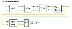
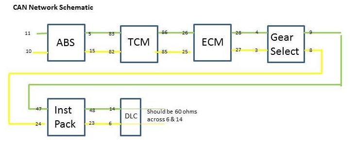
CAN Network Integrity Check without WDS
� With the ignition switched OFF, connect a DVOM between DLC pin 6 (CAN high [+]) and DLC pin 14 (CAN low [-]). A reading of 60 Ω indicates a good CAN bus:
< 60 Ω indicates a short circuit on the bus
> 60 Ω indicates high resistance on the bus
I have 120.5 ohms
� Disconnect the DVOM from the DLC and switch to the voltage scale.
� Switch the ignition ON to position II.
� Connect the DVOM between DLC pin 6 (CAN high [+]) and ground. The measured value should be 2.7 V I have 3.14v
� Connect the DVOM between DLC pin 14 (CAN low [-]) and ground. The measured value should be 2.5 V I have 2.27v
So ............... looks like I have a high resistance on the CAN Network Bus. Does anyone have any experience of what this might be - my guess would be (perhaps) corrosion in a connector somewhere, but that's a guess - no more than that !. Also, can any of the technical experts confirm that diagnosis using WDS in unlikely to give me any more precise information. I'm happy to pay for a full diagnosis, but not if after 30 minutes and �60.00, the report says "High resistance on the CAN Bus" Pretty sure it's not a "battery on it's way out" fault - battery fairly new and charging properly etc. As always - thanks in advance for any advice. Cheers, David.
Thanks Guys - that's very helpful. The wiring looks fairly simple - just a twisted pair of Green / Yellow wires. The connector at the gear selector module is fairly accessible. So - if I were to disconnect that connector, and measure across pins 4 & 3, then 8 & 9, I would expect those resistances to be different, depending on which side (ECM or Inst Pack), the fault to be. Any ideas what I should expect those ohms to be ?
As always - many thanks in advance.
Cheers,
David.
Yes that's right. If it's 120 ohms at 8 & 9 then the fault is further upstream in the direction of the ECM. If high R then fault is Instr. pack side.
The only fly in the ointment is we don't exactly know where Mr. Jaguar put the terminating resistors. By convention they are at the physical ends of the bus (as per the diagram?) so we can perhaps presume one is in the Instr. pack and the other is in the ABS module (not sure where pins 11,12 go - they don't show on a 2003 diagram).
As a last resort you might have to try an external 120 ohm resistor (I have plenty if you need one!) at each relevant module connector and then test that wire for continuity.
Judging by the intermittent nature I'm sure you're only looking at a poor connection; having and internal fault with the terminating resistors would be quite unusual.
Multiplecats - many thanks for that. The pins on the ABS module are not terminated, so if there's a 120 ohm resistor, it's internal rather than external.
Took the car out this morning - no problem driving it as I lose engine temp information but got that via torque, lose speed but got that through Tom Tom sat-nav, and odometer doesn't work but that's a sort-of advantage in a way !! After about 35 minutes - smooth road, 50 mph ish, everything suddenly corrected itself - clocks all working, all lights off, no malfunction messages etc. Got home and with ignition off CAN resistance across DLC is now 60 ohms !
So ........... my gut is telling me it's a faulty connection somewhere, but can't do any further checking until it goes wrong again, which might be two hours, two days, or two weeks. Am grateful for your input, but might not be able to take up your advice and report back until the fault comes back.
Thanks again.
Cheers,
David.
The ADVANCED DIAGNOSTICS student guide from Jaguar training has all the info on the CAN bus. I think I uploaded it to the large file area???
The terminating resistors in the Jaguar CAN bus are in the INST PK and the ABS module. (opposite ends on the bus)
When the CAN bus fault occurs again you can measure resistance of the INST PK and the ABS modules UNPLUGGED to see which module is NOT connected to the BUS if the fault is internal. You could unplug the gearbox illumination module and measure in each direction (toward the INST PK or toward the ABS module) to measure the termination resistor in each of those modules.
The 'illumination module' is a 'LISTEN ONLY' node on the CAN bus so it won't actually communicate.
It would be easier to use a diagnostic devise (PDU, WDS, IDS, SDD, AutoEnginuity, Auto Logic etc.) to try to communicate with each module and determine what one is NOT responding.
From your description of symptoms I would guess the ABS module circuit is at fault.
Thanks for that - in fact, in was from your earlier very helpful post that I got the Service Training Document which enabled me to do the tests already done. When (not "if") the problem re-occurs, I'll do a bit more diagnostic work and try and narrow down the source of the problem. The code (P1638) refers to a fault between INST and ECM - if the problem was in the ABS module, - would it still throw up the same code ?
The other three possible issues - CAN short circuit fault, INST failure and ECM failure seem less likely but still possible I guess.
Thanks again.
David.
If you look at the order of the modules in the network you see that the Gear Sector Module is between the Major Instrument Pack and the ECM. Perhaps that is the circuit where the fault lies?????
Just for others in the future, some of the Jag Electrical Guides for our cars actually show the terminators (e.g. for my car they do, and they're in PCM aka ECM & ICM).
First let me say "Thanks" to the folks on this thread, your information has been very helpful!!
Let me add to the thread, I have also had the "Christmas Tree" experience in my 2001 XJ8, with the restricted performance and all the goodies.
The first time around was approximately 2 years ago. I replaced the thermostat housing, intake manifold gasket(s) and the hoses that are under the intake manifold, and nearby.
For my efforts I found one of the anti-knock sensors had "drown" in the anitfreeze, and had to replace it. At this point I thought I was really doing well, saved quite a bit of money and the car should be good to go. LoL, not so fast!! I started it up, it purred as it should 'til I got to the corner, and the "Christmas Tree" lit up!! I thought I must have REALLY done something bad. I limped home and started research. Some "experts" told me to replace the cluster in the dash. But with a little patience and some help from Jaguar forums, I found a little electrical cleaner on connections under the dash and going to the ECM and TCM fixed the problem.
Fast forward to this week. The finicky Cat is due for her annual check-up (Smog), so I checked the codes and IM readiness, and all was well. I changed clothes, got the registration, and started the car to head for the smog inspection. NOT SO FAST - Christmas Trees all over again - what timing!!
To shorten this story, I have found the when the CAN bus is at 61.5 ohms she purrs like a kitten and runs very happily. When it creeps up to 63.5 - 64 ohms, I get CAN bus errors,restricted performance, and the general Christmas tree effect. That is not much room for error, with dirty connections, heat, and humidity.
I was again able to temporarily resolve the problem cleaning the connection to the ABS module this time. But while it was disconnected I measured the resistance at 119.5 ohms, for the termination in the dash controller. A little quick math means the termination in the ABS module must be around 125 ohms.
I am thinking my next move will be to pull out the ABS module and replace termination resistor a value closer to 120 ohms, so the bus is closer to 60 ohms (instead of 61.5),
I am hoping this will make the bus a little less fragile as humidity and corrosion increase the resistance. Would appreciate any thoughts, comments, experience in this area.
I think you will probably find that the resistance you are measuring on the bus is a symptom of the problem and not the problem itself. In other words simply changing the terminal resistor to drop the overall value you are measuring won't make any difference as the bad connection(s) will still be there.
Anyway if you want to try dropping the resistance of the bus as an experiment, you don't need to change the terminal resistor, you can just add another suitable value resistor across the bus (i.e. in parallel) to bring it down to the value you want. Maybe use a pot so you can fine tune it.
Thank you both for the responses. I do see your point, the 61.5 is a symptom of the problem, not the problem. The ABS module could be right on at 120 ohms, and the bus would still be high when measured from the OBD2 port because of a bad connection in between. I guess I will start by checking the resistance across the ABS module while it is not connected to the bus (it would be with pins 10 & 11, or 5 & 15) according to my diagram, and then decide if I need to work into the module or back across the bus. Thanks again for pointing me in the right direction!!
I've just been out and measured my CAN resistance at the diagnostic connector socket at PINs 6 and 14 and it measures 61.6 ohms. I checked it only out of curiosity as I have not got and never have had any CAN associated problems. I would think the 60 ohm figure is more likely to be a nominal figure with some level of tolerance in the actual value.
Perhaps some others could check that reading on their cars to give is all a better idea of its value in the real world?
Thank you for checking, it would be great if we could get a few other readings as well. For the moment my priority is to get past the smog check. In my car it takes almost 200 miles to switch all of the IM readiness monitors to "OK" (from INC). It won't pass the smog unless these all read "OK".
After that I plan to research it a bit further, starting at the ABS module to check the resistance, and then work my way back through the CAN bus modules.
I have driven this car on a number of long trips and never had a problem. At the moment I am a bit concerned at how fragile this bus seems to be, the difference between the car running normally and the Christmas Tree Effect (CTE) is only a few ohms. I do want to understand if the 61.5 is normal, or it is marginal and a small amount of corrosion will put it over the edge.
If I find anything interesting, I will post it here.
Thank you again to everyone for your efforts, your comments, and your invaluable insight!!
I think it makes a lot of sense to start measuring the resistance at different points, starting with checking that the abs module itself is showing 120Ω when it is disconnected.
I think I would go through every module making sure the values at each harness connector are within spec - cleaning and checking the connectors as I went. Presumably you are going to find different values as you pass the problem connection.
Are the resistance values of the CAN network different when measured at the OBD connector and the ABS module?
same problem,
I have read all the above and followed there suggestions .
i get 120 ohms at the dlc across pins 6 and 14
i get 120 ohms at abs module plug LF37 pins 5 and 15 back through the bus to dlc
i get 120 ohms on the abs module at pins 5 and 15 and 11 and 12 as i understand is correct
i have done continuity checks on the +ve and -ve lines from lf37 to em7, em7 to em10, have still to continue to fc88 and fc25 and dlc but up to now no breaks in bus
the tcm pins 83 to 82 and 85 to 86 show around 35kohms
the ecm pins 25 to 26 and 27 to 28 show around 9.5kohms
on the abs module are pins 8 and 24 both ground common?, mine are not, also pins 9 and 25 both battery live common, again mine are not. if i test pin 8 to 9 i do get i high resistance (forgot to take note) but if i test pns24 to 25 nothing
on the dlc i get 2.4v at pin 6 to ground, and 2.6v at pin14 to ground with ignition at pos 11
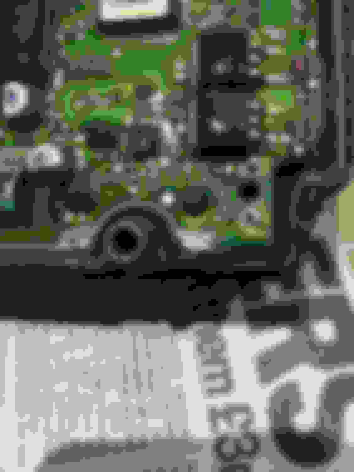
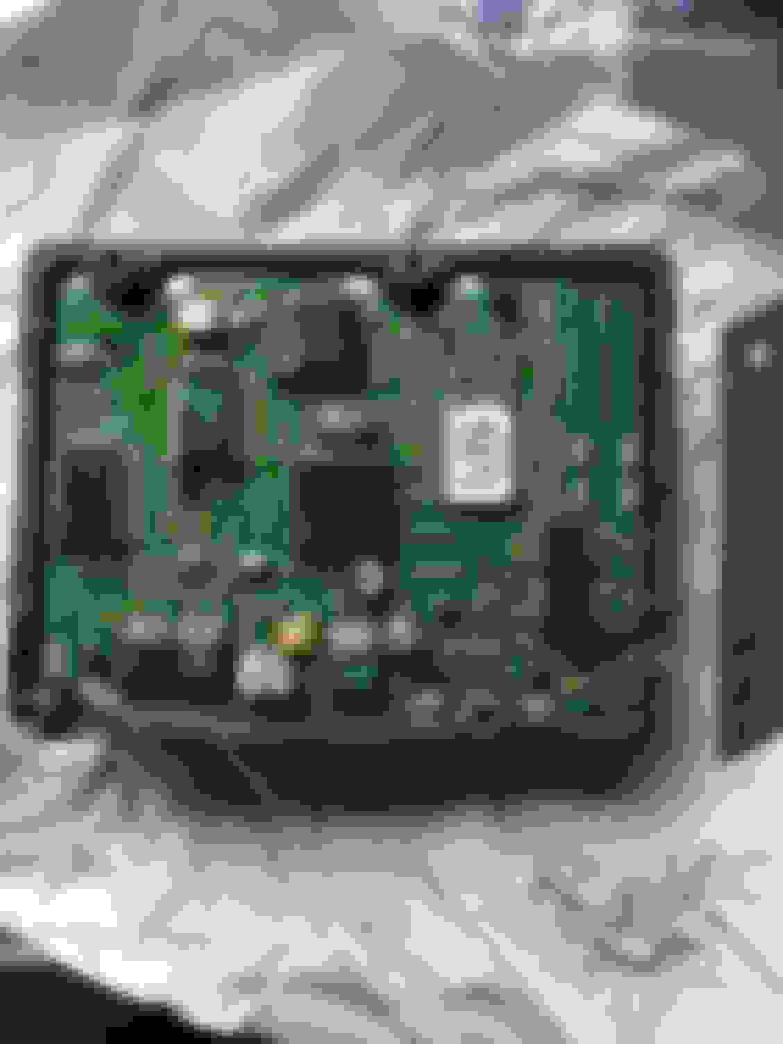
as far as the abs module goes i have tried the resolder fix but mine is different to all the other ones shown mine seems to have a pin showing through the board but NOT soldered to the main copper lands it does have a small ring around the edge of the hole so thinking it was meant to be only soldered to the small ring that is what i did please see photo ,now it might be that it should be soldered across the gap and i have not done so that could be my problem but not wanting to blow the board i did the safe (to me ) thing. if it should be soldered across can somebody confirm it please
regards
rrosscoe