
Heater Pump Removal - "How To"


Thread Starter
|
Veteran Member


Joined: Apr 2012
Posts: 1,854
Likes: 987
From: UK
Guys, I just noticed that I am getting no heat at low RPM, sounds like the heater pump issue.
Has anyone seen a "how to remove" post or article.
I have seen comments saying access after removing the throttle body as well as remove the CAT to access, but no detailed description.
Has anyone seen a "how to remove" post or article.
I have seen comments saying access after removing the throttle body as well as remove the CAT to access, but no detailed description.
Last edited by GGG; Oct 16, 2013 at 05:23 PM. Reason: edit thread title and link to "HOW TO" thread

Popular Reply
Jun 12, 2013, 09:57 AM

Banned
Joined: Feb 2012
Posts: 517
Likes: 27
From: London
Before you do anything else, check to see if your front fog lights and fog light tell tale switches in the cabin work.
If they don't, check number 3 fuse in the forward engine bay fuse box, beside your engine oil dipstick.
That fuse also controls the heater.
If that fuse is ok, but your heater doesn't work, removing the throttle body will give you much better access to the heater control valve and heater pump.
In fact I wouldn't try to remove the latter without removing the throttle body.
I've had my throttle body off twice now, but both times I took the inlet manifold off with the lower half of it.
However you can leave the inlet manifold in place, and unbolt the throttle body from it.
Cooling system
Remove the header tank cap.
Locate the radiator drain plug on the rear facing lower right hand side of the radiator.
Place a suitable container under the drain plug, loosen the drain plug and drain the coolant.
Retighten the drain plug.
Remove the header tank coolant hoses and disconnect the coolant fluid sensor multiplug underneath it.
Remove the header tank.
Throttle body
Release the intake tube to air filter box clamp.
Remove the breather pipe from the camshaft cover.
Remove the intake tube to throttle body bolts, and remove the intake tube (pic 1)
Turn the throttle cable wheel clockwise to slacken the cable, and remove the cable. (pic 2)
Remove the throttle cable bracket screws from the top of the throttle body.
There are three multiplug connections on each side of the throttle body that must be disconnected. (pics 2 & 4)
One of these multiplugs ( cmp harness) each side has a large red tab. (pic 3)
Slide the red tab backwards to release. Those multiplugs are attached with brackets that screw in to the throttle body. Remove the screws to release the brackets. A magnetic headed screwdriver would be handy if you have one, to avoid dropping the screws down the back of the engine.
Attached to the back of the upper throttle body is a ribbed breather hose, which is a squeeze and pull release. These ribbed hoses are known to be fragile, so be careful with them.
Also on the back of the upper throttle body is a coolant hose, with the common eared clamp. Squeeze the clamp ears together, slide the clamp backwards and pull the pipe off. (pic 6)
You may need to wedge a flathead screwdriver in the gap between the throttle body tube and hose, and work the hose backwards with the screwdriver while pulling it.
Now you have the upper throttle body separated from it's electrical connections and pipes/hoses, remove the (4) bolts in the top of the throttle body, to separate the upper and lower halves of the throttle body.
This will make access to the lower throttle body easier.
Save the metal gasket between the two halves for refitting, unless it looks damaged.
On the lower left side is another of those ribbed breather hoses. (pic 5)
On each side of the lower throttle body is a vacuum hose which is a pull off/push on fit. Pull it off. The assistance of a flathead screwdriver to help work the pipes off may be handy here too. (pics 7 & 8)
The lower throttle body is upside down in those pictures, they were the best pics I had of the lower throttle body.
On the right hand side of the lower throttle body is the brake booster vacuum pipe, which fits in to a female plastic ring. You can see the black ring in (pic 8 again).
Remove the booster pipe.
The lower throttle body itself is attached to the intake elbow by two bracket bolts, one each side. You can see one of the bracket bolts in (pic 3) bove the red tabbed multiplug. Remove them.
Remove the 7 lower throttle body housing to intake manifold bolts.
Remove the lower throttle body.
Heater control valve and heater pump.
The heater pump is bolted to the bottom of a bracket, which in turn is bolted to the firewall at the back of the engine bay. (pic 9)
There are two multiplugs attached to the top of the bracket, one for the pump and one for the heater control valve. Disconnect them.
The heater control valve is bolted to the top end of the same bracket, and will have to be removed at the same time.
Then you can lift out the bracket with the heater pump and heater control valve attached to it.
Or to make it a little easier, unbolt the heater control valve from the bracket first.
Be patient, the heater hoses you just disconnected from the heater control valve, will be in the way.
Don't split any trying to yank it out, just be careful and patience will do it.
(pic 10) shows my old heater pump attached to the bottom of the bracket.
Mark the hoses with their respective heater control valve connections (tippex, felt pen etc), so you don't re-attach the wrong hose to the wrong connection.
If you do get stuck reconnecting the hoses, refer to the diagram
It took me 3 or 4 hours to remove the intake manifold, throttle body, heater control valve and heater pump.
And about the same to put them back.
If I can do it, you can do it.
Good luck.
P.S. this was intended as a rough guide to get you started until somebody came forward with better instructions.
But since to date no one has, i'm editing this as I go along to make it a bit more of a how to.
Last edited by Roadhogg; Jun 17, 2013 at 10:20 AM.

Senior Member
Joined: Jul 2011
Posts: 568
Likes: 192
From: Jacksonville
I had mine replaced by the dealership as it was clear that it couldn't be replaced from underneath without removing the exhaust. As well, I knew the octopus hose needed to be replaced on my car, it was seeping in several places. The mechanic told me that the throttle body needs to come out to get to the pump. He said it is difficult, but obviously can be done, just takes time and a lot of bending over. Said his back really was hurting the next day. Also stated hat after 15 years with the dealership it was only the 2nd of these he has had to replace.
Banned
Joined: Feb 2012
Posts: 517
Likes: 27
From: London
Before you do anything else, check to see if your front fog lights and fog light tell tale switches in the cabin work.
If they don't, check number 3 fuse in the forward engine bay fuse box, beside your engine oil dipstick.
That fuse also controls the heater.
If that fuse is ok, but your heater doesn't work, removing the throttle body will give you much better access to the heater control valve and heater pump.
In fact I wouldn't try to remove the latter without removing the throttle body.
I've had my throttle body off twice now, but both times I took the inlet manifold off with the lower half of it.
However you can leave the inlet manifold in place, and unbolt the throttle body from it.
Cooling system
Remove the header tank cap.
Locate the radiator drain plug on the rear facing lower right hand side of the radiator.
Place a suitable container under the drain plug, loosen the drain plug and drain the coolant.
Retighten the drain plug.
Remove the header tank coolant hoses and disconnect the coolant fluid sensor multiplug underneath it.
Remove the header tank.
Throttle body
Release the intake tube to air filter box clamp.
Remove the breather pipe from the camshaft cover.
Remove the intake tube to throttle body bolts, and remove the intake tube (pic 1)
Turn the throttle cable wheel clockwise to slacken the cable, and remove the cable. (pic 2)
Remove the throttle cable bracket screws from the top of the throttle body.
There are three multiplug connections on each side of the throttle body that must be disconnected. (pics 2 & 4)
One of these multiplugs ( cmp harness) each side has a large red tab. (pic 3)
Slide the red tab backwards to release. Those multiplugs are attached with brackets that screw in to the throttle body. Remove the screws to release the brackets. A magnetic headed screwdriver would be handy if you have one, to avoid dropping the screws down the back of the engine.
Attached to the back of the upper throttle body is a ribbed breather hose, which is a squeeze and pull release. These ribbed hoses are known to be fragile, so be careful with them.
Also on the back of the upper throttle body is a coolant hose, with the common eared clamp. Squeeze the clamp ears together, slide the clamp backwards and pull the pipe off. (pic 6)
You may need to wedge a flathead screwdriver in the gap between the throttle body tube and hose, and work the hose backwards with the screwdriver while pulling it.
Now you have the upper throttle body separated from it's electrical connections and pipes/hoses, remove the (4) bolts in the top of the throttle body, to separate the upper and lower halves of the throttle body.
This will make access to the lower throttle body easier.
Save the metal gasket between the two halves for refitting, unless it looks damaged.
On the lower left side is another of those ribbed breather hoses. (pic 5)
On each side of the lower throttle body is a vacuum hose which is a pull off/push on fit. Pull it off. The assistance of a flathead screwdriver to help work the pipes off may be handy here too. (pics 7 & 8)
The lower throttle body is upside down in those pictures, they were the best pics I had of the lower throttle body.
On the right hand side of the lower throttle body is the brake booster vacuum pipe, which fits in to a female plastic ring. You can see the black ring in (pic 8 again).
Remove the booster pipe.
The lower throttle body itself is attached to the intake elbow by two bracket bolts, one each side. You can see one of the bracket bolts in (pic 3) bove the red tabbed multiplug. Remove them.
Remove the 7 lower throttle body housing to intake manifold bolts.
Remove the lower throttle body.
Heater control valve and heater pump.
The heater pump is bolted to the bottom of a bracket, which in turn is bolted to the firewall at the back of the engine bay. (pic 9)
There are two multiplugs attached to the top of the bracket, one for the pump and one for the heater control valve. Disconnect them.
The heater control valve is bolted to the top end of the same bracket, and will have to be removed at the same time.
Then you can lift out the bracket with the heater pump and heater control valve attached to it.
Or to make it a little easier, unbolt the heater control valve from the bracket first.
Be patient, the heater hoses you just disconnected from the heater control valve, will be in the way.
Don't split any trying to yank it out, just be careful and patience will do it.
(pic 10) shows my old heater pump attached to the bottom of the bracket.
Mark the hoses with their respective heater control valve connections (tippex, felt pen etc), so you don't re-attach the wrong hose to the wrong connection.
If you do get stuck reconnecting the hoses, refer to the diagram
It took me 3 or 4 hours to remove the intake manifold, throttle body, heater control valve and heater pump.
And about the same to put them back.
If I can do it, you can do it.
Good luck.
P.S. this was intended as a rough guide to get you started until somebody came forward with better instructions.
But since to date no one has, i'm editing this as I go along to make it a bit more of a how to.
If they don't, check number 3 fuse in the forward engine bay fuse box, beside your engine oil dipstick.
That fuse also controls the heater.
If that fuse is ok, but your heater doesn't work, removing the throttle body will give you much better access to the heater control valve and heater pump.
In fact I wouldn't try to remove the latter without removing the throttle body.
I've had my throttle body off twice now, but both times I took the inlet manifold off with the lower half of it.
However you can leave the inlet manifold in place, and unbolt the throttle body from it.
Cooling system
Remove the header tank cap.
Locate the radiator drain plug on the rear facing lower right hand side of the radiator.
Place a suitable container under the drain plug, loosen the drain plug and drain the coolant.
Retighten the drain plug.
Remove the header tank coolant hoses and disconnect the coolant fluid sensor multiplug underneath it.
Remove the header tank.
Throttle body
Release the intake tube to air filter box clamp.
Remove the breather pipe from the camshaft cover.
Remove the intake tube to throttle body bolts, and remove the intake tube (pic 1)
Turn the throttle cable wheel clockwise to slacken the cable, and remove the cable. (pic 2)
Remove the throttle cable bracket screws from the top of the throttle body.
There are three multiplug connections on each side of the throttle body that must be disconnected. (pics 2 & 4)
One of these multiplugs ( cmp harness) each side has a large red tab. (pic 3)
Slide the red tab backwards to release. Those multiplugs are attached with brackets that screw in to the throttle body. Remove the screws to release the brackets. A magnetic headed screwdriver would be handy if you have one, to avoid dropping the screws down the back of the engine.
Attached to the back of the upper throttle body is a ribbed breather hose, which is a squeeze and pull release. These ribbed hoses are known to be fragile, so be careful with them.
Also on the back of the upper throttle body is a coolant hose, with the common eared clamp. Squeeze the clamp ears together, slide the clamp backwards and pull the pipe off. (pic 6)
You may need to wedge a flathead screwdriver in the gap between the throttle body tube and hose, and work the hose backwards with the screwdriver while pulling it.
Now you have the upper throttle body separated from it's electrical connections and pipes/hoses, remove the (4) bolts in the top of the throttle body, to separate the upper and lower halves of the throttle body.
This will make access to the lower throttle body easier.
Save the metal gasket between the two halves for refitting, unless it looks damaged.
On the lower left side is another of those ribbed breather hoses. (pic 5)
On each side of the lower throttle body is a vacuum hose which is a pull off/push on fit. Pull it off. The assistance of a flathead screwdriver to help work the pipes off may be handy here too. (pics 7 & 8)
The lower throttle body is upside down in those pictures, they were the best pics I had of the lower throttle body.
On the right hand side of the lower throttle body is the brake booster vacuum pipe, which fits in to a female plastic ring. You can see the black ring in (pic 8 again).
Remove the booster pipe.
The lower throttle body itself is attached to the intake elbow by two bracket bolts, one each side. You can see one of the bracket bolts in (pic 3) bove the red tabbed multiplug. Remove them.
Remove the 7 lower throttle body housing to intake manifold bolts.
Remove the lower throttle body.
Heater control valve and heater pump.
The heater pump is bolted to the bottom of a bracket, which in turn is bolted to the firewall at the back of the engine bay. (pic 9)
There are two multiplugs attached to the top of the bracket, one for the pump and one for the heater control valve. Disconnect them.
The heater control valve is bolted to the top end of the same bracket, and will have to be removed at the same time.
Then you can lift out the bracket with the heater pump and heater control valve attached to it.
Or to make it a little easier, unbolt the heater control valve from the bracket first.
Be patient, the heater hoses you just disconnected from the heater control valve, will be in the way.
Don't split any trying to yank it out, just be careful and patience will do it.
(pic 10) shows my old heater pump attached to the bottom of the bracket.
Mark the hoses with their respective heater control valve connections (tippex, felt pen etc), so you don't re-attach the wrong hose to the wrong connection.
If you do get stuck reconnecting the hoses, refer to the diagram
It took me 3 or 4 hours to remove the intake manifold, throttle body, heater control valve and heater pump.
And about the same to put them back.
If I can do it, you can do it.
Good luck.
P.S. this was intended as a rough guide to get you started until somebody came forward with better instructions.
But since to date no one has, i'm editing this as I go along to make it a bit more of a how to.
Last edited by Roadhogg; Jun 17, 2013 at 10:20 AM.
Banned
Joined: Feb 2012
Posts: 517
Likes: 27
From: London
Bit more info.
If you do take it out yourself, there's a place up north called jaguar spares north east.
I've bought several items from the guy that runs it, and that's one guy that DOES know his stuff.
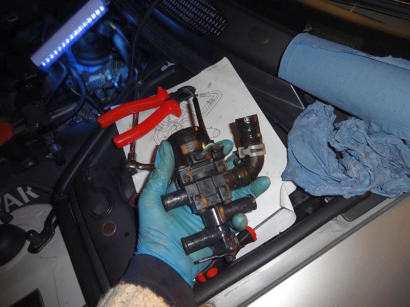
If you send him your heater pump he'll send it to a guy that will recondition it properly for about �75 and give it back to you in about 4 days.
His number is 0191 586 7770.
My pump came back like this.
If you do take it out yourself, there's a place up north called jaguar spares north east.
I've bought several items from the guy that runs it, and that's one guy that DOES know his stuff.
If you send him your heater pump he'll send it to a guy that will recondition it properly for about �75 and give it back to you in about 4 days.
His number is 0191 586 7770.
My pump came back like this.
Thread Starter
|
Veteran Member
Joined: Apr 2012
Posts: 1,854
Likes: 987
From: UK
Thanks for the write up that will make the job a lot easier. Unfortunately its is not the fuse, the fogs are working fine. Looks like another job to add to the list, at least this one can wait till the end of the summer.
Thanks also for the recon tips, I also found a web page showing how to do that so will have a go myself, here it is.
http://www.jagrepair.com/HeaterPumpMotor.htm
Thanks also for the recon tips, I also found a web page showing how to do that so will have a go myself, here it is.
http://www.jagrepair.com/HeaterPumpMotor.htm
Last edited by RaceDiagnostics; Jun 12, 2013 at 03:06 PM.
Banned
Joined: Feb 2012
Posts: 517
Likes: 27
From: London
Yes, I considered rebuilding the pump myself, but I found the 3 screws on the pump body really tight, and the first one I tried started to burr the thread.
I would suggest giving those screws a good dousing in penetrating oil and leaving it a while to soak in before attempting to remove them, and before the attempt, try to clean out any penetrating fluid from those Philips head grooves to give you a better grip in the screw head.
Burring the screw head a little caused my decision not to mess with it, and pay the money in exchange for the warranty in the end.
By all means have a go though, and if you don't have any problems with the screws, all the better to proceed.
I've edited my first post with a little more info in the hope it clarifies things a bit more.
Thread Starter
|
Veteran Member
Joined: Apr 2012
Posts: 1,854
Likes: 987
From: UK
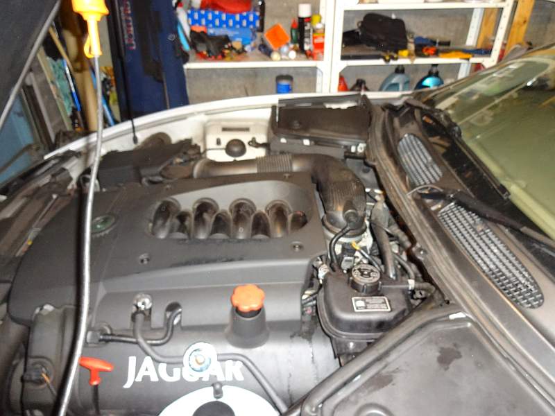
I started on this job today.
First my plan was to drain the coolant, but found that the drain plug is totally inaccessible so instead opted for this large storage box to catch the various dribbles as I go along.

Next the coolant header tank taking care with the coolant level sensor connector.

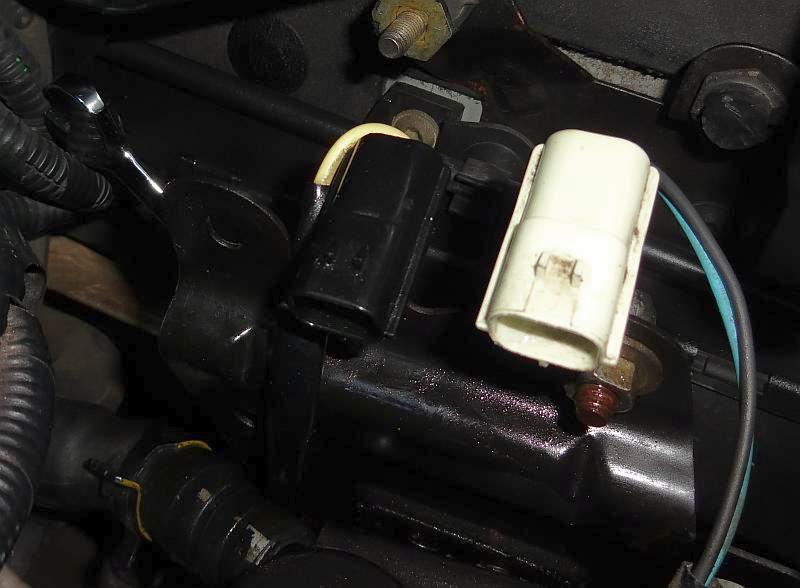
Then these two electrical connectors.

Then this air pipe and electrical connector.

Then the air intake duct.

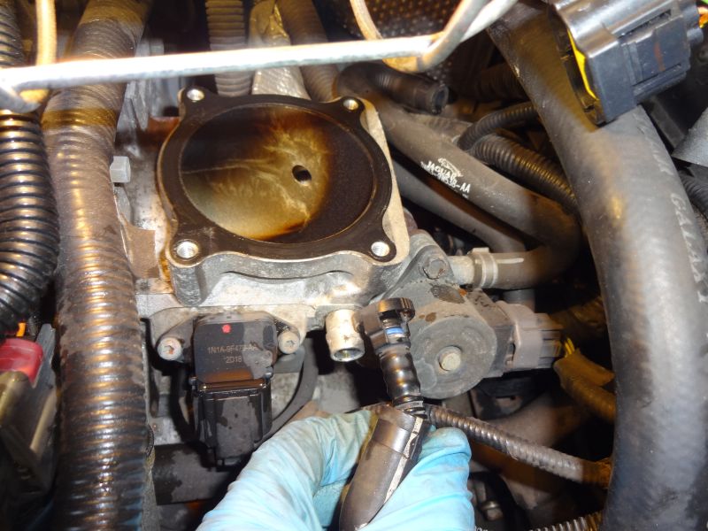
Next was this electrical connector on the right, two coolant hoses and the four bolts to remove the throttle body.

Once the throttle body was off I removed this air hose to get a bit more access.
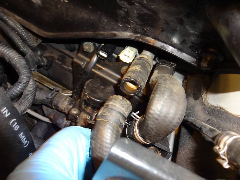
I the went on to try to get the hose clips off the water valve and got a bit stuck, the access is so restricted I could not get in there with any pliers to release them.

So I ordered one of these, which should get delivered on Monday.

Does anyone have any tips for removing the hose from its fitting after the clip is off. I assume they will be stuck fast.
First my plan was to drain the coolant, but found that the drain plug is totally inaccessible so instead opted for this large storage box to catch the various dribbles as I go along.
Next the coolant header tank taking care with the coolant level sensor connector.
Then these two electrical connectors.
Then this air pipe and electrical connector.
Then the air intake duct.
Next was this electrical connector on the right, two coolant hoses and the four bolts to remove the throttle body.
Once the throttle body was off I removed this air hose to get a bit more access.
I the went on to try to get the hose clips off the water valve and got a bit stuck, the access is so restricted I could not get in there with any pliers to release them.
So I ordered one of these, which should get delivered on Monday.
Does anyone have any tips for removing the hose from its fitting after the clip is off. I assume they will be stuck fast.
Trending Topics
Veteran Member
Joined: Jun 2011
Posts: 2,134
Likes: 543
From: Costa Mesa, CA
I have that tool- invaluable. I try and twist the hose with my hands first, the GENTLY with vice grips if needed. Once they twist, they come off without too much trouble. There is probably a spreading tool to remove hoses, just haven't seen one.
Thread Starter
|
Veteran Member
Joined: Apr 2012
Posts: 1,854
Likes: 987
From: UK
OK, day two, spent two hours on this tonight, slow progress but it was progress.
The clip removal tool was great, pricy at �30 but worth it.
First I wanted to get this hose off, I pulled, twisted, poured boiling water over it but it would not budge.

So I cut it off, if anyone knows the part number then please let me know, I will replace if cheap, or repair if expensive.
edit - i found a replacement http://britishparts.co.uk/products/5...ater-MJA6721AG
After an hours pushing, pulling and prising I got the two hoses on the left off.

And after another 30 mins got the hose off of the non return valve.

That's it for tonight, not too much to show for two hours effort.
The clip removal tool was great, pricy at �30 but worth it.
First I wanted to get this hose off, I pulled, twisted, poured boiling water over it but it would not budge.
So I cut it off, if anyone knows the part number then please let me know, I will replace if cheap, or repair if expensive.
edit - i found a replacement http://britishparts.co.uk/products/5...ater-MJA6721AG
After an hours pushing, pulling and prising I got the two hoses on the left off.
And after another 30 mins got the hose off of the non return valve.
That's it for tonight, not too much to show for two hours effort.
Last edited by RaceDiagnostics; Oct 1, 2013 at 05:01 PM.
Thread Starter
|
Veteran Member
Joined: Apr 2012
Posts: 1,854
Likes: 987
From: UK
Not just yet, I almost wanted to give up tonight, it is a hell of a job, but there is no going back now.
Thread Starter
|
Veteran Member
Joined: Apr 2012
Posts: 1,854
Likes: 987
From: UK
Day 3
First I was able to prise off the bottom right hose after another 15 minutes of tweaking.
Next I thought I would try to remove the valve, it is held on the bracket by two bolts through the back of the bracket, so first you need to release these two nuts to be able to tilt the bracket forwards to gain access to the backside. One came off the other spun on the rubber support peg.

Access to the bolts on the back is tricky, you can see the spanner on the left here, so it needs to be done by touch.
This is the single nut from the front that came off and the two bolts holding the valve to the bracket from the back.

With these removed the valve could be lifted out, but I had to cut the wiring to the plug as I couldn't work out how to get the plug off the bracket.
This is the view with the valve out.

Next on to the hose that connects to the front of the pump, another 15 mins spent prising this one off.
Now I thought that the bracket with the pump would lift out now but it seemed to be still attached at the bottom. The bit of angle bracket at the bottom seemed to be tied to the chassis.

On closer inspection there were two more rubber mounts that sheared when I tried to remove the nuts, but should be easily replaced.

In theory the pump and bracket should then just lift out, well after a lot of twisting and manipulation it finally came out.

Believe it or not it did come out of here.
This is what the bracket was mounted to.

Tomorrow I will strip the motor. Does anyone know which is the positive and negative connection for the valve and pump?
First I was able to prise off the bottom right hose after another 15 minutes of tweaking.
Next I thought I would try to remove the valve, it is held on the bracket by two bolts through the back of the bracket, so first you need to release these two nuts to be able to tilt the bracket forwards to gain access to the backside. One came off the other spun on the rubber support peg.
Access to the bolts on the back is tricky, you can see the spanner on the left here, so it needs to be done by touch.
This is the single nut from the front that came off and the two bolts holding the valve to the bracket from the back.
With these removed the valve could be lifted out, but I had to cut the wiring to the plug as I couldn't work out how to get the plug off the bracket.
This is the view with the valve out.
Next on to the hose that connects to the front of the pump, another 15 mins spent prising this one off.
Now I thought that the bracket with the pump would lift out now but it seemed to be still attached at the bottom. The bit of angle bracket at the bottom seemed to be tied to the chassis.
On closer inspection there were two more rubber mounts that sheared when I tried to remove the nuts, but should be easily replaced.
In theory the pump and bracket should then just lift out, well after a lot of twisting and manipulation it finally came out.
Believe it or not it did come out of here.
This is what the bracket was mounted to.
Tomorrow I will strip the motor. Does anyone know which is the positive and negative connection for the valve and pump?
Thread Starter
|
Veteran Member
Joined: Apr 2012
Posts: 1,854
Likes: 987
From: UK
Tonight's update.
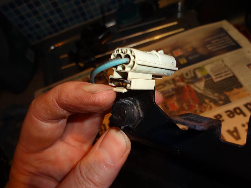
First here is how to remove the connectors from the frame rather than cutting the wires, lever the tab downwards and it will pull off, of course this will be done blind when it is in situ.
The pump off the frame and screws that need to be removed, before doing that I tested with a power supply, it was dead.


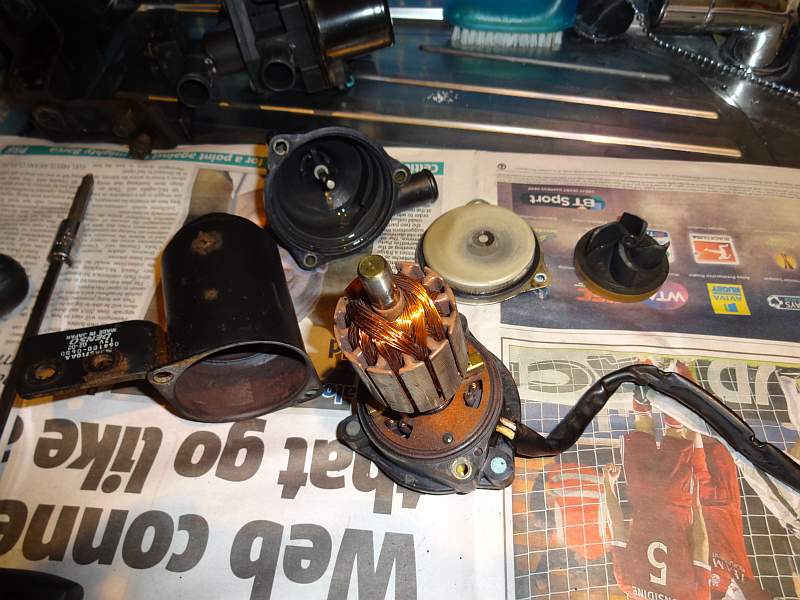
This is how the brushes looked, completely worn down.

Close up you can see one of the tails was disconnected.

You need to remove this bolt to free up the rotor to get acces to take the old brusdes out and new ones in.

This was one of the brushes that just fell out.

This is the other brush.

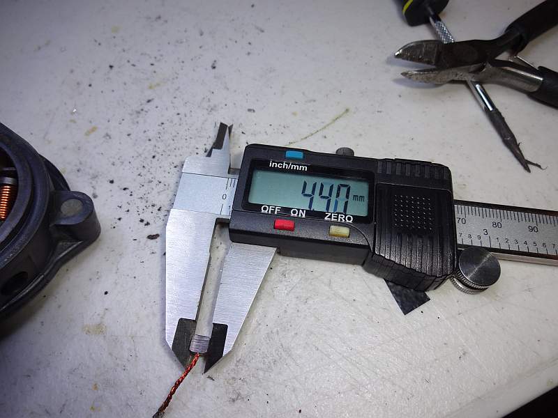
When you are looking for replacements then note this size, 4,4mm square with the tail on the side. Buy a brush spec'ed for a low voltage long running motor, rather than a mains voltage power tool.
These were the only brushes I had lying around, a bit too big so I orderd some 5mm by 8mm side tail ones off ebay which I will sand down to the correct size.

Now I could not get the rotor out of the PCB so I decided to remove the PCB, however this is not necessary and does not help. I sanded down the platic "rivets" to free it up.

Then desoldered the coils the lie beneath.

However this does not help as the end bearing is a push fit and not easily removed and in fact does not need to be removed to replace the brsuhes, so don't do what I did.

As you can see from here you have plenty access space to replace the brushes, I just have to wait for them to turn up from my ebay purchase.

So next I repaired the cut wires for the valve, soldered then heat shrink.


And then on to repair the hose that I cut, Jag wanted �33 for the hose so I decided to repair.


I'm not really sure if this will hold, I think I will also use some glue.
Comments on this are welcome.
First here is how to remove the connectors from the frame rather than cutting the wires, lever the tab downwards and it will pull off, of course this will be done blind when it is in situ.
The pump off the frame and screws that need to be removed, before doing that I tested with a power supply, it was dead.
This is how the brushes looked, completely worn down.
Close up you can see one of the tails was disconnected.
You need to remove this bolt to free up the rotor to get acces to take the old brusdes out and new ones in.
This was one of the brushes that just fell out.
This is the other brush.
When you are looking for replacements then note this size, 4,4mm square with the tail on the side. Buy a brush spec'ed for a low voltage long running motor, rather than a mains voltage power tool.
These were the only brushes I had lying around, a bit too big so I orderd some 5mm by 8mm side tail ones off ebay which I will sand down to the correct size.
Now I could not get the rotor out of the PCB so I decided to remove the PCB, however this is not necessary and does not help. I sanded down the platic "rivets" to free it up.
Then desoldered the coils the lie beneath.
However this does not help as the end bearing is a push fit and not easily removed and in fact does not need to be removed to replace the brsuhes, so don't do what I did.
As you can see from here you have plenty access space to replace the brushes, I just have to wait for them to turn up from my ebay purchase.
So next I repaired the cut wires for the valve, soldered then heat shrink.
And then on to repair the hose that I cut, Jag wanted �33 for the hose so I decided to repair.
I'm not really sure if this will hold, I think I will also use some glue.
Comments on this are welcome.
Thread Starter
|
Veteran Member
Joined: Apr 2012
Posts: 1,854
Likes: 987
From: UK
These bits turned up today, the rubber stand offs were a rip off, Jag wanted �13 each, Brit Parts �4 each but with �10 shipping.
The brushes were these CARBON BRUSHES ALTERNATOR FIAT BOSCH MARELLI ISKRA LARDA LUCAS CARGO BX1852 B8 | eBay

Did a bit of sanding but a bit of sandpaper would have been just as good.

Got them to ~4.4mm cross section.

A bit of trial fitting without the springs.

Ended up with this length for each side, the tail was inset by about 1.5mm.

Getting the brushes in place with the springs was really tricky, it took four hands!
I used a dab of epoxy glue to replace the plastic rivet on each side.

And then soldered up the tails and the end of the coils from beneath.

That's it for tonight as I need to wait for the epoxy to set, next I will retest and refit.
I'm off for the a bit if hill walking the next few days so no update till next week now.
10 points if you can name this hill.

The brushes were these CARBON BRUSHES ALTERNATOR FIAT BOSCH MARELLI ISKRA LARDA LUCAS CARGO BX1852 B8 | eBay
Did a bit of sanding but a bit of sandpaper would have been just as good.
Got them to ~4.4mm cross section.
A bit of trial fitting without the springs.
Ended up with this length for each side, the tail was inset by about 1.5mm.
Getting the brushes in place with the springs was really tricky, it took four hands!
I used a dab of epoxy glue to replace the plastic rivet on each side.
And then soldered up the tails and the end of the coils from beneath.
That's it for tonight as I need to wait for the epoxy to set, next I will retest and refit.
I'm off for the a bit if hill walking the next few days so no update till next week now.
10 points if you can name this hill.


Thread Starter
|
Veteran Member
Joined: Apr 2012
Posts: 1,854
Likes: 987
From: UK
I reassembled the pump today and tested it, all went well.
www.jagspares.net are sending me a replacement pump hose, once that arrives I'll get everything back into the car.
www.jagspares.net are sending me a replacement pump hose, once that arrives I'll get everything back into the car.
Thread Starter
|
Veteran Member
Joined: Apr 2012
Posts: 1,854
Likes: 987
From: UK
The hose turned up thanks to Trevor at Jag Spares who sent it to me for free! so I am back on the job, but I should have done this while I was waiting.
The bottom of this rubber support peg was pretty stubborn, and would be a 2 man job to get off with someone holding from the top as someone else wrenching from below. So in the end I dremeled it off.

And then painted it.

And painted the support bracket.

I will try to get it back together tomorrow but Kim wants me to fix the central heating first.
The bottom of this rubber support peg was pretty stubborn, and would be a 2 man job to get off with someone holding from the top as someone else wrenching from below. So in the end I dremeled it off.
And then painted it.
And painted the support bracket.
I will try to get it back together tomorrow but Kim wants me to fix the central heating first.
Thread Starter
|
Veteran Member
Joined: Apr 2012
Posts: 1,854
Likes: 987
From: UK
I got the central heating fixed in the house so back onto the car.
Most everything put back in and looking good, just the header tank to go, getting it all back in was a struggle.

And finally it is complete.
Filled it up and ran it for 10 mins, no leaks, and the heater works at idle!
So jumped in and drove it out of the garage and noticed that the orange MIL light was on, arghhh!
Cleared (P1647) it and went for a drive, all was well, no leaks and no MIL light.
Stopped the car and popped the bonnet to have a look, still no leaks, great.
Restarted the car and the MIL light came back on again, P1647 again.

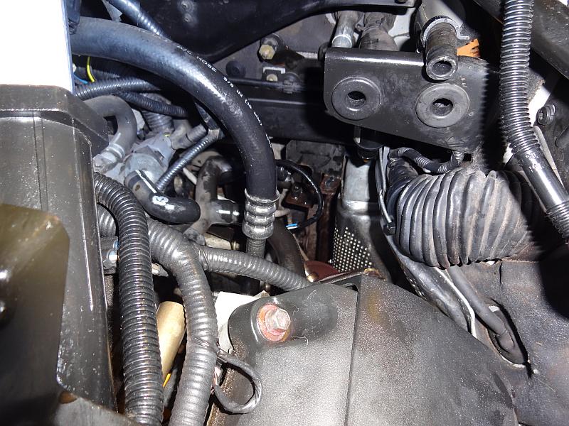
So had a look at the O2 sensor outputs, they all look good, so I don't understand what is triggering the fault code.
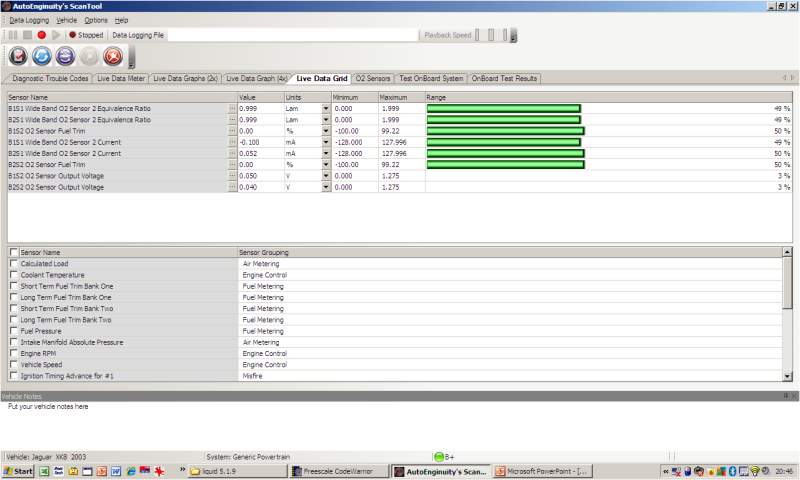
Can anyone say where the O2 sensor leads go to, I will need to check that the connectors are properly seated.
Most everything put back in and looking good, just the header tank to go, getting it all back in was a struggle.
And finally it is complete.
Filled it up and ran it for 10 mins, no leaks, and the heater works at idle!
So jumped in and drove it out of the garage and noticed that the orange MIL light was on, arghhh!
Cleared (P1647) it and went for a drive, all was well, no leaks and no MIL light.
Stopped the car and popped the bonnet to have a look, still no leaks, great.
Restarted the car and the MIL light came back on again, P1647 again.
So had a look at the O2 sensor outputs, they all look good, so I don't understand what is triggering the fault code.
Can anyone say where the O2 sensor leads go to, I will need to check that the connectors are properly seated.
Last edited by RaceDiagnostics; Oct 14, 2013 at 04:20 PM.
Thread Starter
|
Veteran Member
Joined: Apr 2012
Posts: 1,854
Likes: 987
From: UK
From the repair manual I got this.
Description
P1647 Left-Hand ECM HO2S control
malfunction
Possible source
HO2S heater failure
HO2S sensing circuit; short
circuit to ground, short circuit
to high voltage, open circuit,
Action
For HO2S tests, GO to Pinpoint Test J. and GO to
Pinpoint Test K. Contact dealer technical support
for advice on possible ECM failure
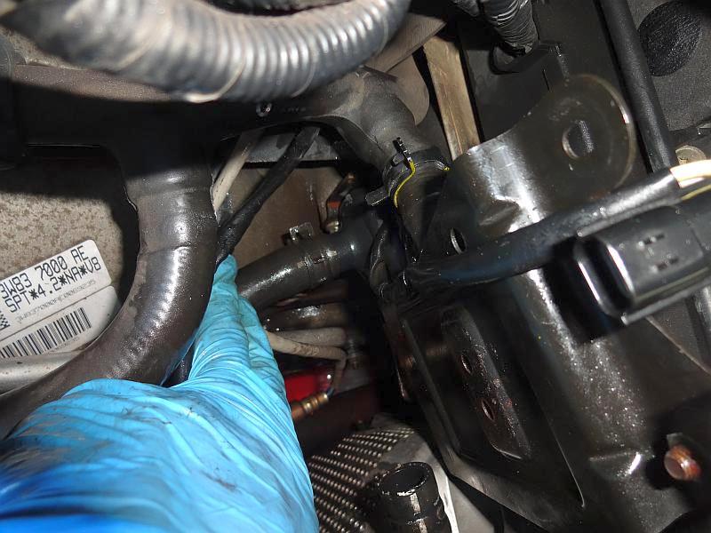
As far as I can tell the issue is with the top O2 sensor under the coolant header tank and the connector is here.
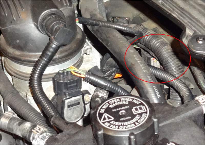
Please let me know if I have got this wrong.
Description
P1647 Left-Hand ECM HO2S control
malfunction
Possible source
HO2S heater failure
HO2S sensing circuit; short
circuit to ground, short circuit
to high voltage, open circuit,
Action
For HO2S tests, GO to Pinpoint Test J. and GO to
Pinpoint Test K. Contact dealer technical support
for advice on possible ECM failure
As far as I can tell the issue is with the top O2 sensor under the coolant header tank and the connector is here.
Please let me know if I have got this wrong.