
Help Sorting Tail Light Wiring!


Thread Starter
|
Senior Member


Joined: Oct 2013
Posts: 735
Likes: 286
From: Las Vegas, NV, USA
Morning Lads,
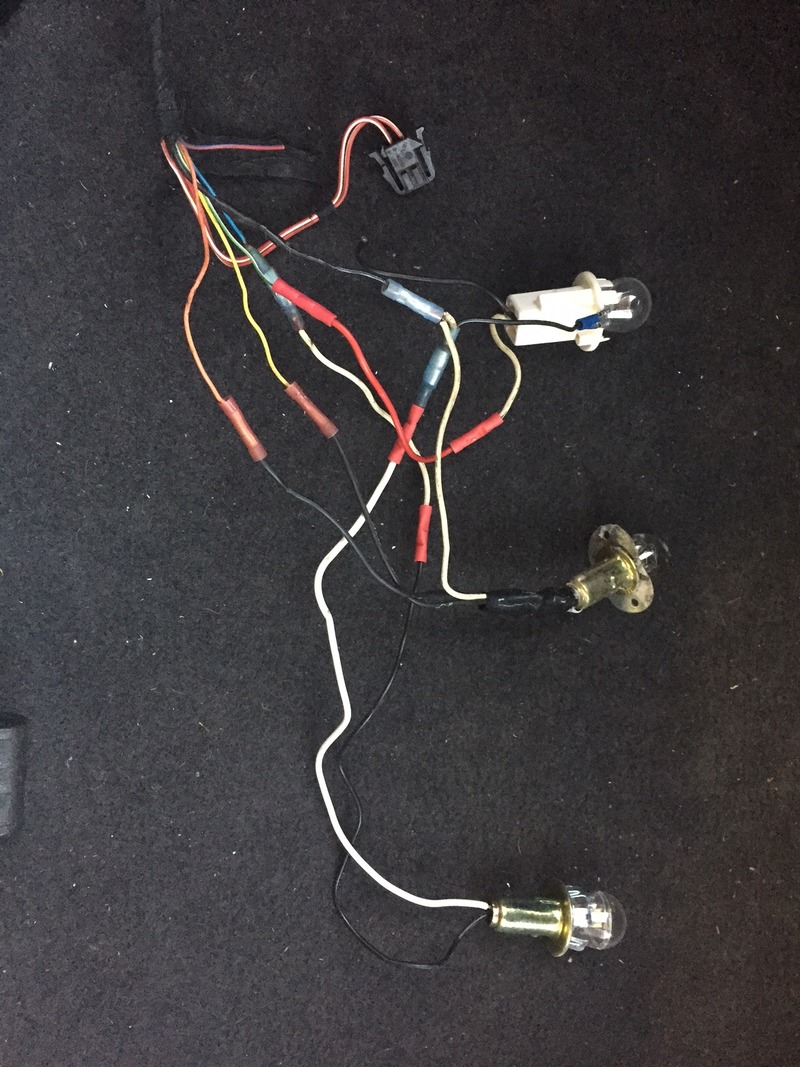
So the car I bought came with the aftermarket dual round tail lights. Looks pretty cool but it was obvious that there were some issues.
The red lenses were bubbled from overheating from bulbs and the light output was very dim. I discovered yesterday after digging into it that its a bloody mess in there. The lenses are indeed garbage which is one thing but the wiring that had been done to make things were was really poorly done.
So I set about correcting the issue, replacing the melted lenses with some nice LED round tail lights. I had to cut out the opening to get it all to fit but it worked and they "physically" look fantastic.
So now the hard part which is sorting through this wiring.
Does anyone have a schematic for the tail light wiring?
I suspect that there used to be some sort of multipin connector that was used to power the stock tail lights but that is long since gone and someone has crimped a series of wires to make things work.
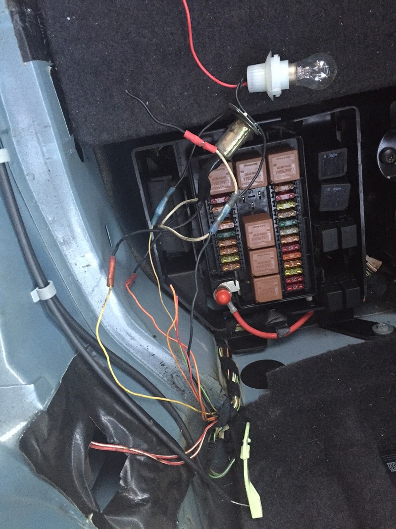
What I noticed first was that there were two power leads that were stuffed into the sockets of two of the relays you see in the picture. This is confusing as is the light gauge of wiring used to power up the tail lights.
My assumption right now is that the entire tail light gets a constant 12V feed and then the smaller wires are connected to some sort of module that applies a ground to whatever lamp needs to be illuminated? Grasping at straws right now until I get some firm intel to work with.
Can someone jump in and help me sort through this?
What is the original configuration of the wiring and the lamps? This should go a long way in sorting through this mess. You'll notice that there are wires that were cut and left hanging so I really want to know what everything was originally intended to do?
So the car I bought came with the aftermarket dual round tail lights. Looks pretty cool but it was obvious that there were some issues.
The red lenses were bubbled from overheating from bulbs and the light output was very dim. I discovered yesterday after digging into it that its a bloody mess in there. The lenses are indeed garbage which is one thing but the wiring that had been done to make things were was really poorly done.
So I set about correcting the issue, replacing the melted lenses with some nice LED round tail lights. I had to cut out the opening to get it all to fit but it worked and they "physically" look fantastic.
So now the hard part which is sorting through this wiring.
Does anyone have a schematic for the tail light wiring?
I suspect that there used to be some sort of multipin connector that was used to power the stock tail lights but that is long since gone and someone has crimped a series of wires to make things work.
What I noticed first was that there were two power leads that were stuffed into the sockets of two of the relays you see in the picture. This is confusing as is the light gauge of wiring used to power up the tail lights.
My assumption right now is that the entire tail light gets a constant 12V feed and then the smaller wires are connected to some sort of module that applies a ground to whatever lamp needs to be illuminated? Grasping at straws right now until I get some firm intel to work with.
Can someone jump in and help me sort through this?
What is the original configuration of the wiring and the lamps? This should go a long way in sorting through this mess. You'll notice that there are wires that were cut and left hanging so I really want to know what everything was originally intended to do?


Joined: Apr 2012
Posts: 25,865
Likes: 4,708
From: Summerville, South Carolina
There is a link in the How to's or Here's the link to the electrical guide pdf on Gus's web site which should help
http://www.jagrepair.com/images/Auto.../jagxk2003.pdf
http://www.jagrepair.com/images/Auto.../jagxk2003.pdf
Thread Starter
|
Senior Member
Joined: Oct 2013
Posts: 735
Likes: 286
From: Las Vegas, NV, USA
There is a link in the How to's or Here's the link to the electrical guide pdf on Gus's web site which should help
http://www.jagrepair.com/images/Auto.../jagxk2003.pdf
http://www.jagrepair.com/images/Auto.../jagxk2003.pdf
Great place to start
Thank You!
Thread Starter
|
Senior Member
Joined: Oct 2013
Posts: 735
Likes: 286
From: Las Vegas, NV, USA
So after exploring the wiring for a while, it appears I may have an issue with the security module in the rear.
Both the park lights and the marker lights on the rear of the car are powered through the same relay. The marker lamps continue to work and the relay is good but I have no park lights.
The park lights go first through the security module mounted underneath the fuse panel in the rear and I believe that this is where the issue is. Since the wiring and the lamp assemblies were so botched up in the rear of the car, I assume that the box was somehow damaged by all of this. Maybe it is the wiring but I won't know until I get the box out. If the wiring doesn't look melted, then I really won't know until I get another box to try.
I have also discovered that I only have a brake light on the left side as well. No voltage getting to the right side - they also flow through the same security module.
I do have indicators but they do not flow through that box so that makes sense. Haven't checked the backup lights or rear fog yet.
How do I identify a used replacement security module that will work on the 2003 MY and what things will need to be done to it once its installed? Are there things that the dealer are going to have to do or do I simply need to pair my keyfob to it and I'm done?
Cheers
Bernie
Veteran Member
Joined: Apr 2014
Posts: 4,813
Likes: 3,027
From: Jersey, Channel Islands
What a bird's nest. 
Fog lamps are fed via R1 and F15 in trunk fuse box and don't pass through the SLCM, although the reversing lamps do.
From the symptoms you describe it's entirely possible that the SLCM has suffered: the wires poked into the relay sockets are probably an attempt to bypass it to get lamps to work.
If you've completed getting the wiring back to a healthy state and still have missing lamps, then I'd be tempted to open up the module (I'm assuming here that it's like the older ones and can be dismantled without needing a saw) and check if there are any obviously damaged components inside.
If you do find anything fried, I would look to having it repaired if possible as it's a programmable module. Any replacement will need to match the numbers on the SLM entry on the VCATS label down in the spare wheel well.
HTH,
Mike
PS Make sure you get 'canbus compliant' LEDS if you go that route else you'll be plagued with 'bulb fail rear' messages. Probably best to stay with normal bulbs until you get it sorted.
Last edited by michaelh; Mar 27, 2016 at 02:15 PM. Reason: add ps
Thread Starter
|
Senior Member
Joined: Oct 2013
Posts: 735
Likes: 286
From: Las Vegas, NV, USA
What a bird's nest.
Fog lamps are fed via R1 and F15 in trunk fuse box and don't pass through the SLCM, although the reversing lamps do.
From the symptoms you describe it's entirely possible that the SLCM has suffered: the wires poked into the relay sockets are probably an attempt to bypass it to get lamps to work.
If you've completed getting the wiring back to a healthy state and still have missing lamps, then I'd be tempted to open up the module (I'm assuming here that it's like the older ones and can be dismantled without needing a saw) and check if there are any obviously damaged components inside.
If you do find anything fried, I would look to having it repaired if possible as it's a programmable module. Any replacement will need to match the numbers on the SLM entry on the VCATS label down in the spare wheel well.
HTH,
Mike
PS Make sure you get 'canbus compliant' LEDS if you go that route else you'll be plagued with 'bulb fail rear' messages. Probably best to stay with normal bulbs until you get it sorted.
I actually had to replace the housings completely so I opted to replace them with LED housings. I figured I would just use resistors on the leads to get by any quick flash or warnings on the dash. That will be a stage two issue to sort.
As far as I can tell, the SLM is indeed in need of help so I am going to pull it today to see if I can get inside it without too much issue. Yes, once I understood the layout via the schematic, all wiring is cleaned up and the wires running under the relays made sense.
B
Thread Starter
|
Senior Member
Joined: Oct 2013
Posts: 735
Likes: 286
From: Las Vegas, NV, USA
Hey Lads,
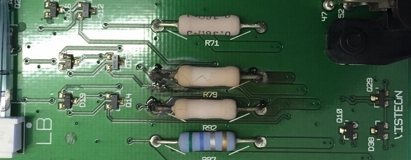
The problem with the SLM has been found.
See attached picture.
The rest of the PCB and its components look fine and the traces on the affected parts seem to have survived as well.
Now can I get help identifying the two resistors here? The markings have evaporated so I need help sourcing replacements.
I found another post that shows these to possibly be a 1ohm resistor rated at 5 watts at 5%
Would just like to know for sure
Cheers
Bernie

Last edited by razorboy; Mar 30, 2016 at 08:42 PM.
Trending Topics
Thread Starter
|
Senior Member
Joined: Oct 2013
Posts: 735
Likes: 286
From: Las Vegas, NV, USA
Update on my tail light repair.
So I have replaced the two bad resistors in the SLM and I now have my tail light circuits back up and running.
However, I am still short a right hand brake light.
It has voltage but only 10 volts. The left side is making the proper 12.
On the PCB next to the two bad resistor lives another resistor.
It didn't look bad on the first go but after examining more closely, it might be bad as well.
Question:
Are resistors either working or not working or can they go partially bad restricting voltage?
The resistor is R71 in the photo. The two larger green resistors are the ones I just changed out. Can someone tell me if that resistor is part of the brake light circuit?
B


Bernie,
Since you already have the PCB out, why not un-solder R71 and measure its value? 0.36 ohm is a very low resistance indeed. Common resistor faults can be either open, short, or partial...
Good luck on tracking down the culprit.
Since you already have the PCB out, why not un-solder R71 and measure its value? 0.36 ohm is a very low resistance indeed. Common resistor faults can be either open, short, or partial...
Good luck on tracking down the culprit.
Veteran Member
Joined: Apr 2014
Posts: 4,813
Likes: 3,027
From: Jersey, Channel Islands
Almost certainly (in the absence of a circuit diagram) R71 is for a brake lamp, with R62 being for the other.
As Pristine says, resistors can go high value.
Something obviously not right: if you have 10V at the lamp then is it lit up at all?
Mike
As Pristine says, resistors can go high value.
Something obviously not right: if you have 10V at the lamp then is it lit up at all?
Mike
Thread Starter
|
Senior Member
Joined: Oct 2013
Posts: 735
Likes: 286
From: Las Vegas, NV, USA
I can plug a bulb on the circuit today prior to pulling the resistor(s) off the PCB. If one is bad, I might as well swap them both out.
Will update
Veteran Member
Joined: Apr 2014
Posts: 4,813
Likes: 3,027
From: Jersey, Channel Islands
OK, then measure on both ends of the 0.36 ohm resistor R71. As there's no load (no lamp), you should read the same voltage, which should also be the same as on R62 (the other 0.36 ohm).
If you've got 12V on one side and 10V on the other, then R71 is dud. Most multimeters will struggle to measure such low resistances accurately.
I had a quick look on Google and they're available from a few sources; you might find the supplier of your 1 ohm ones can oblige.
While you're in there, agreed swopping them both as R62 may have been cooked and survived, only to fail once you've buttoned everything back up again

Nearly there
Mike
P.S. You can prove by temporarily shorting out R71. If that's the problem you'll get your brake light back (along with a bulb fail message)
Last edited by michaelh; Apr 11, 2016 at 12:52 PM.
Thread Starter
|
Senior Member
Joined: Oct 2013
Posts: 735
Likes: 286
From: Las Vegas, NV, USA
Ah - mea culpa - I'd assumed that you had it back in circuit.
OK, then measure on both ends of the 0.36 ohm resistor R71. As there's no load (no lamp), you should read the same voltage, which should also be the same as on R62 (the other 0.36 ohm).
If you've got 12V on one side and 10V on the other, then R71 is dud. Most multimeters will struggle to measure such low resistances accurately.
I had a quick look on Google and they're available from a few sources; you might find the supplier of your 1 ohm ones can oblige.
While you're in there, agreed swopping them both as R62 may have been cooked and survived, only to fail once you've buttoned everything back up again
Nearly there
Mike
P.S. You can prove by temporarily shorting out R71. If that's the problem you'll get your brake light back (along with a bulb fail message)
That would be an easy test
Veteran Member
Joined: Apr 2014
Posts: 4,813
Likes: 3,027
From: Jersey, Channel Islands
If all is well on the power input side you should. Quickest check would be to measure both sides of R71. It should read 12V (or to be strictly accurate, the battery voltage) if you don't have the bulb in circuit.
Thread Starter
|
Senior Member
Joined: Oct 2013
Posts: 735
Likes: 286
From: Las Vegas, NV, USA
One was reading .204
The other is reading .000
Can you help me pick the appropriate replacements from Digikey?
DigiKey Electronics - Electronic Components Distributor
Veteran Member
Joined: Apr 2014
Posts: 4,813
Likes: 3,027
From: Jersey, Channel Islands
Odd. You're reading one as a dead short and the other almost in the ballpark. Something doesn't add up. Can you get the voltages on each side of where R62 & R71 locate?
Digikey has none in stock, and....
min order quantities means you'll be paying over $100
Just about to jump in the bath (too much information) - I'll do a search once I'm smelling sweeter.
Mike
Digikey has none in stock, and....
min order quantities means you'll be paying over $100
Just about to jump in the bath (too much information) - I'll do a search once I'm smelling sweeter.
Mike
Veteran Member
Joined: Apr 2014
Posts: 4,813
Likes: 3,027
From: Jersey, Channel Islands
Tricky.
The best I can find is on the 'bay:
0 36 Ohm 36R 3 Watts 3W 1 Metal Film Resistors 8 Pieces | eBay
They're not wirewound, but 3W rating will give a reasonable margin assuming ~2A draw from a normal brake light.
Winding back somewhat, can you confirm 12V on BT42-6 (orange wire) and particularly one side of R71. Need to be sure that the correct voltage is getting in. If you can rig up a test lamp that would be better than the multimeter here as it would show up any poor contact.
It may be the light, but looking at your picture the soldering on the bottom rightmost contact on the 10-way connector (there's what looks like number 52 next to it) looks burnt. Resolder it if so. That connector is BT42 and thus relevant.
Mike
Thread Starter
|
Senior Member
Joined: Oct 2013
Posts: 735
Likes: 286
From: Las Vegas, NV, USA
Tricky.
The best I can find is on the 'bay:
0 36 Ohm 36R 3 Watts 3W 1 Metal Film Resistors 8 Pieces | eBay
They're not wirewound, but 3W rating will give a reasonable margin assuming ~2A draw from a normal brake light.
Winding back somewhat, can you confirm 12V on BT42-6 (orange wire) and particularly one side of R71. Need to be sure that the correct voltage is getting in. If you can rig up a test lamp that would be better than the multimeter here as it would show up any poor contact.
It may be the light, but looking at your picture the soldering on the bottom rightmost contact on the 10-way connector (there's what looks like number 52 next to it) looks burnt. Resolder it if so. That connector is BT42 and thus relevant.
Mike
The best I can find is on the 'bay:
0 36 Ohm 36R 3 Watts 3W 1 Metal Film Resistors 8 Pieces | eBay
They're not wirewound, but 3W rating will give a reasonable margin assuming ~2A draw from a normal brake light.
Winding back somewhat, can you confirm 12V on BT42-6 (orange wire) and particularly one side of R71. Need to be sure that the correct voltage is getting in. If you can rig up a test lamp that would be better than the multimeter here as it would show up any poor contact.
It may be the light, but looking at your picture the soldering on the bottom rightmost contact on the 10-way connector (there's what looks like number 52 next to it) looks burnt. Resolder it if so. That connector is BT42 and thus relevant.
Mike
The solder joints on the connectors are all perfect.
I will do a test to see what kind of voltage I am getting on those traces. Guess I would need to reinsert the resistors to see if a bulb lights though?
Thanks for your help on this.
Thread Starter
|
Senior Member
Joined: Oct 2013
Posts: 735
Likes: 286
From: Las Vegas, NV, USA
Did a quick test on the traces with the resistors removed.
Getting 12.35 volts on one side and 2.25 volts on the other for both resistor locations.
Looking at how jacked up the lighting was on the rear on this car, I believe that these resistors have also been damaged or at least that one.
Get the same measured results every time.
For a few dollars its more than worth swapping them out.
What about that resistor you showed me?
It's not ceramic like the ones I removed?
B
Veteran Member
Joined: Apr 2014
Posts: 4,813
Likes: 3,027
From: Jersey, Channel Islands
Agreed replace them both. The ones on the 'bay are metal film which will be most likely on a ceramic substrate. I think that they will do the job.
If you want to check further while they arrive, you could put temporary wire bridges across where they are located in the SLM. You'll get a message when you brake, but at least you will be able to use the car.
Mike