
TPS replacement

Thread Starter
|
Veteran Member
Joined: Dec 2011
Posts: 6,278
Likes: 690
From: Limousin, France
Graham (GGG) is kindly sending over his dead TPS for a bit of diagnosis to see what we can do about repair/replacement.
As soon as I get it to bits I'll post the results
As soon as I get it to bits I'll post the results
Last edited by steveinfrance; Jul 31, 2012 at 05:08 AM.
Thread Starter
|
Veteran Member
Joined: Dec 2011
Posts: 6,278
Likes: 690
From: Limousin, France
The programmable land Jaguar version is �120 ish.
2 x O-5 V o/p, Hall effect so unlimited cycles.
It can be programmed to give FSD O/P between 20� and 360� rotation.
2 x O-5 V o/p, Hall effect so unlimited cycles.
It can be programmed to give FSD O/P between 20� and 360� rotation.
Thread Starter
|
Veteran Member
Joined: Dec 2011
Posts: 6,278
Likes: 690
From: Limousin, France
Right so it's a 90� rotation twin gang linear 2.4K pot.
On this one one track is bad.
Good track (with 5.1 V across the pot)
Closed 0.02 V WOT 4.6 V
Bad track
Closed 1.06 V WOT 4.7 V
The bad track is bad up to about 50 % throttle then tracks the good one.
Probably reflects Graham's over-cautious driving habits!!
Off to the Post Mortem room now.
On this one one track is bad.
Good track (with 5.1 V across the pot)
Closed 0.02 V WOT 4.6 V
Bad track
Closed 1.06 V WOT 4.7 V
The bad track is bad up to about 50 % throttle then tracks the good one.
Probably reflects Graham's over-cautious driving habits!!
Off to the Post Mortem room now.
Thread Starter
|
Veteran Member
Joined: Dec 2011
Posts: 6,278
Likes: 690
From: Limousin, France
OK so here's the guts
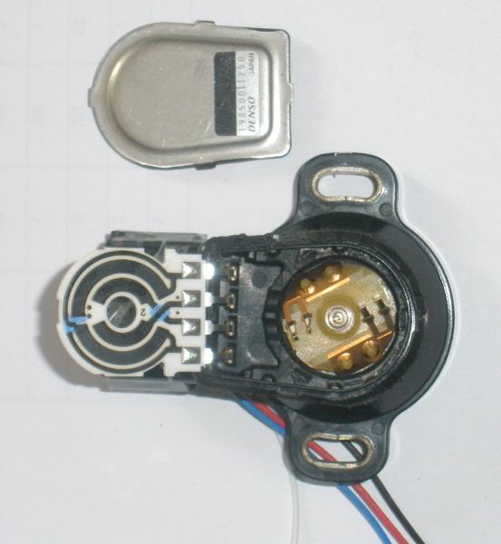
With a microscope it is evident that both tracks are worn over the first 40% or so and the defective one has some visible cracking.
There's no way of fixing this but what we have got is a very nice support for a non-contact rotary sensor complete with connector !
What I'm thinking is to use a Hall or inductive sensor with either the magnet or bit of steel mounted on the bit that carries the wipers.
This would give the requires 0 - 5v o/p but only single ended.
The use of two pots, of course, is to provide redundancy but the reliability of a non contact sensor is such that this is not needed (indeed many pot type TPS's are single ended)
I'm pretty sure that if the output pins (2+3) were commoned the ECU wouldn't know anything was wrong.


Joined: Dec 2011
Posts: 120,439
Likes: 17,018
From: Durham, UK
Steve,
A bit of history on this failed TPS you've examined:
11 Nov 2011: first instance of P0121 at 80263 miles
18 Nov 2011: second instance of P0121 at 80332 miles
22 Nov 2011: third, fourth & fifth instances of P0121 at 80512, 80611 and 80696 miles
23 Nov 2011: changed Throttle Body - no further trouble
At each failure, the MIL illuminated. Clearing the codes enabled the vehicle to be started after the first four instances of P0121 until the fifth occurence when it was terminal.
Failure was without warning the first time but after only another 433 miles the TPS was toast.
Does it appear to have been arcing that's broken down the first 'bad' track or some kind of physical failure of the material?
Graham
Last edited by GGG; Aug 3, 2021 at 02:46 AM. Reason: Typo in mileage
Thread Starter
|
Veteran Member
Joined: Dec 2011
Posts: 6,278
Likes: 690
From: Limousin, France
Graham,
Definitely not arcing. I haven't got photomicrograph facilities here, just a binocular microscope.
It's a plastic film pot and the defective track has fine radial striations as if it had broken up under vibration.
Just to clarify the pic the white carrier has two concentric tracks deposited on it and the rotating part has two sets of twin wipers than short the tracks together.
I cleaned the tracks + wipers to no avail - there is clear physical damage.
Thanks, BTW, for sending it.
What we want now is someone with a dead TPS prepared to try a non-contact sensor.
Last edited by steveinfrance; Jul 30, 2012 at 09:07 AM.
Joined: Dec 2011
Posts: 120,439
Likes: 17,018
From: Durham, UK
If you want to put a non-contact sensor together, I've still got the TB here. If anyone with a 4.0 litre (preferably in the UK to keep shipping costs down) is prepared to try it, we can send them the whole assembly.
Graham
Graham
Trending Topics
Thread Starter
|
Veteran Member
Joined: Dec 2011
Posts: 6,278
Likes: 690
From: Limousin, France
The plot thickens and I don't understand.
This will take some explaining so here goes

This is the resistor layout. If we number the solder pads 1 2 3 4 from L to R
Pad 1 +5V
Pad 2 o/p 1 (the good one, practically 0 v throttle closed
Pad 3 o/p 2 the 'bad' one, o/p ~1v throttle closed
Pad 4 Gnd
The diagonal white line represents the wiper position at closed throttle.
The wipers short out tracks 1i to track 1o and 2i to 2o
The +5V goes to 2o at 11 o'clock and 1o at 5 o'clock (the blue bits are insulating bridges)
Gnd goes into 1o at 1 o'clock and 2o at 5.30 (just by the RH black dot) via the blue bridge so 1o and 2o have 5v along their lengths.
The outer tracks are 2.3 K ohms, the inner are conductive.
Notice the wiper position at throttle closed.
The wiper is touching 1o where gnd comes in so returns 0v
BUT the wiper is already some way around 2o, away from the ground point and, indeed, if I put a probe on the track where #2 wiper would be I measure 1V.
At the moment I really don't have an explanation for this.
I propose to lubricate the grey cells appropriately.
I'll be back!!
This will take some explaining so here goes
This is the resistor layout. If we number the solder pads 1 2 3 4 from L to R
Pad 1 +5V
Pad 2 o/p 1 (the good one, practically 0 v throttle closed
Pad 3 o/p 2 the 'bad' one, o/p ~1v throttle closed
Pad 4 Gnd
The diagonal white line represents the wiper position at closed throttle.
The wipers short out tracks 1i to track 1o and 2i to 2o
The +5V goes to 2o at 11 o'clock and 1o at 5 o'clock (the blue bits are insulating bridges)
Gnd goes into 1o at 1 o'clock and 2o at 5.30 (just by the RH black dot) via the blue bridge so 1o and 2o have 5v along their lengths.
The outer tracks are 2.3 K ohms, the inner are conductive.
Notice the wiper position at throttle closed.
The wiper is touching 1o where gnd comes in so returns 0v
BUT the wiper is already some way around 2o, away from the ground point and, indeed, if I put a probe on the track where #2 wiper would be I measure 1V.
At the moment I really don't have an explanation for this.
I propose to lubricate the grey cells appropriately.
I'll be back!!
Senior Member
Joined: Nov 2011
Posts: 581
Likes: 208
From: Devon, UK
You would have thought that the point between 2g and 2o would have been coated with a conductive compound. Incorrect manufacture? Design fault?
Presumably corrected/allowed for in the ECM programming?!
Presumably corrected/allowed for in the ECM programming?!
Thread Starter
|
Veteran Member
Joined: Dec 2011
Posts: 6,278
Likes: 690
From: Limousin, France
I think that's the answer, they can obviously use conductive/resistive coatings as needed and I suspect the two black dots are relevant here.
It would be a seriously major undertaking to get the ECM to sort this out because you've got one linear o/p and one with a most curious law, neither log nor lin.
Unless the ECM can do floating point arithmetic (which I doubt) it's a non-starter.
Last edited by steveinfrance; Jul 30, 2012 at 12:21 PM.
Thread Starter
|
Veteran Member
Joined: Dec 2011
Posts: 6,278
Likes: 690
From: Limousin, France
I have sourced a simpler 90� 0-5 v o/p sensor but need to find out what a good TPS puts out from the two pots. I would expect it to be the same but if they really have built in an offset to prevent someone connecting both ECU inputs to the remaining good pot we're a bit stuffed.
Veteran Member

Joined: Oct 2008
Posts: 4,881
Likes: 1,431
From: Sunny Southport UK
I wonder how these guys do it?
Remanufactured throttle bodies/air mass meters.
A few members I understand have used their service. I'd be most interested in an uprated version, I struggled with a TB on it's way out with the 1121 code, ended up making up a TB with various spares, now waiting for that TPS to go Kaput.
If you can find an answer Steve I'm willing to test it.
Thread Starter
|
Veteran Member
Joined: Dec 2011
Posts: 6,278
Likes: 690
From: Limousin, France
I understand Denso have an agreement with Jaguar not to supply the TPS to anyone else.
I also believe there is a Denso TPS that's got the same characteristics but different pinouts but so far this is apocryphal.
It seems almost criminal to me to use a mechanical pot here.
'For want of a nail' and all that.
I also believe there is a Denso TPS that's got the same characteristics but different pinouts but so far this is apocryphal.
It seems almost criminal to me to use a mechanical pot here.
'For want of a nail' and all that.
Senior Member
Joined: Nov 2011
Posts: 581
Likes: 208
From: Devon, UK
I tried to post yesterday, but for some reason this thread was locked!!
When you say both tracks are 2.3k, is it measured from 2g - 5v or 2o - 5v? If the tracks are both the same compound/resistance per mm you would expect 2g - 5v to be higher, say 2.8k. and allow for the measured 1 volt drop at 2o.
If that was the case both pots would still track together, with a constant 1 volt difference. Much easier for the ECM to allow for.
Edit:
Looking at the pot again, both tracks are connected in parallel so they should read the same. You need to open one of the outside link tracks to isolate the 2 resistance tracks!??
Last edited by Stumpy; Aug 5, 2012 at 04:03 PM. Reason: additional
Thread Starter
|
Veteran Member
Joined: Dec 2011
Posts: 6,278
Likes: 690
From: Limousin, France
Derek,
That was Translator playing about with the Forum
If they did as you suggest it would be easy to spoof.
I'll recheck but I'm pretty sure both are 2.3/2.4 K
Edit (after thinking)
That won't work, both pot 'top ends' are at 5V so one goes from 0-5 and the other from 1-5 for 90� rotation
This will be the output

More tomorrow - I'm also going to put a needle probe into my TPS and see what the volts are on a working one.
The things I do for JF !!
That was Translator playing about with the Forum
If they did as you suggest it would be easy to spoof.
I'll recheck but I'm pretty sure both are 2.3/2.4 K
Edit (after thinking)
That won't work, both pot 'top ends' are at 5V so one goes from 0-5 and the other from 1-5 for 90� rotation
This will be the output
More tomorrow - I'm also going to put a needle probe into my TPS and see what the volts are on a working one.
The things I do for JF !!
Last edited by steveinfrance; Aug 4, 2012 at 04:33 AM.
Thread Starter
|
Veteran Member
Joined: Dec 2011
Posts: 6,278
Likes: 690
From: Limousin, France
The two pots are as described, one has an offset so the O/P voltage of the two are as shown in the graph above.
The ECM processes both voltages as a cross check.
This means we can't just replace the TPS with a contactless rotary transducer giving 0-5 v for 90� rotation, we also need an op amp to mimic the offset output.
I can see no technical merit in this arrangement, two 0-5 v outputs would be just as failsafe so I have to assume it is done deliberately
1. To prevent someone commoning the two outputs to one 'good' track
2. To prevent replacement with an off the shelf device.
Last edited by steveinfrance; Sep 1, 2012 at 03:34 AM.
Veteran Member
Joined: Jan 2012
Posts: 2,953
Likes: 1,120
From: Phoenix, AZ USA
Do you know that the ECM using the difference as a simple cross check?
If it is just a check then A-B might only need to be in a certain range. But...
What you've got in your plot is a linear voltage differential with throttle position and I can at least fathom why someone would want a differential measurement in an electrically noisy environment. Although the resolution you get from 0-1V does make me wonder a bit.
If that were the case spoofing could be a matter of holding one line at a fixed Va and varying the other from Va to Va+1.
Noise might be an issue but it seems like a reasonably safe test engine off and you could watch the interpreted throttle position as a function of input voltage.
Last edited by ccfulton; Sep 1, 2012 at 04:55 AM.
Thread Starter
|
Veteran Member
Joined: Dec 2011
Posts: 6,278
Likes: 690
From: Limousin, France
Charlie,
I'm inferring the Jaguar ECM uses the same logic as Toyota.
If you look at P4 on the attached you'll see a similar (but not identical) setup explained.
I think we'd need to provide a 0-5 and a spoofed O/P derived from it.
My problem is that I don't have a TPS problem and my altruism stops at spending �100 on an inductive sensor, matching it up to the mechanics and seeing if I can make it work.
What we need is someone with the 'throttle body's worth more than my car' syndrome who wants to have a go.
Veteran Member
Joined: Jan 2012
Posts: 2,953
Likes: 1,120
From: Phoenix, AZ USA
Hmm... The text on p4 sounds of the kind of thing an engineer might write for field service in explaining why there are two sensors with different output slopes while trying to avoid explaining differential signals.
For a test, I wasn't meaning anything so elegant. I only meant spoofing the voltage input to see if the interpreted response by the ECU was sensible. A bench test of sorts.
Purpose being to confirm the assumptions about what signal (or combination of signals) represents a throttle position.
The magic smoke leaked out of my AE dongle while testing a beta software for them so I wont be able to much beyond witty commentary for a few days but this is an interesting mystery.