


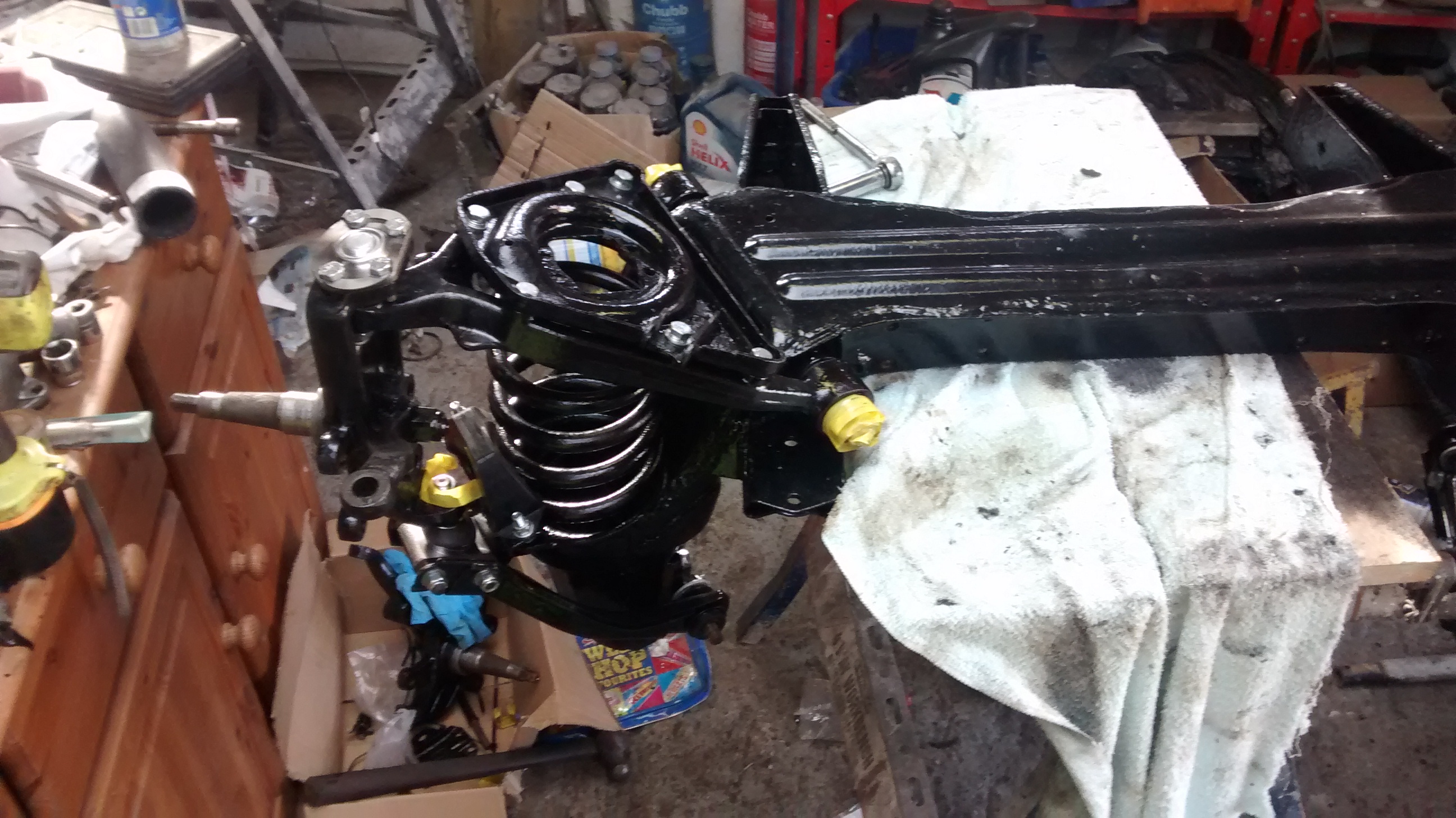
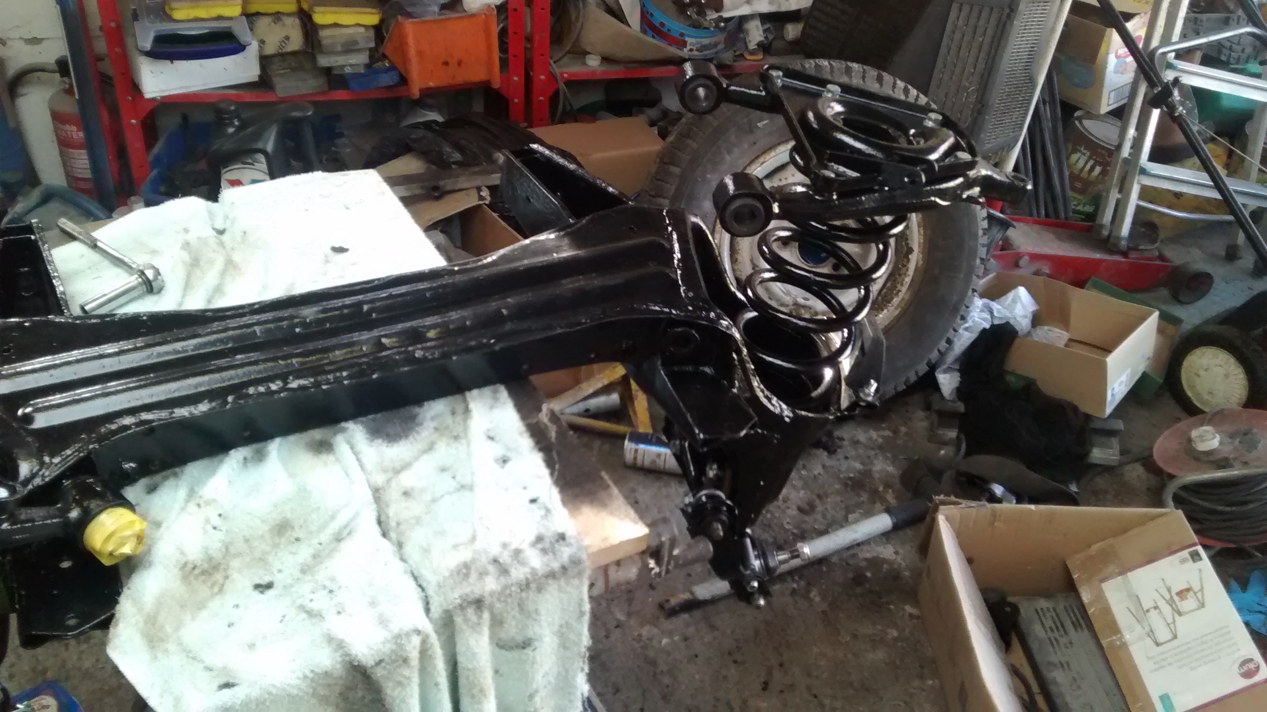
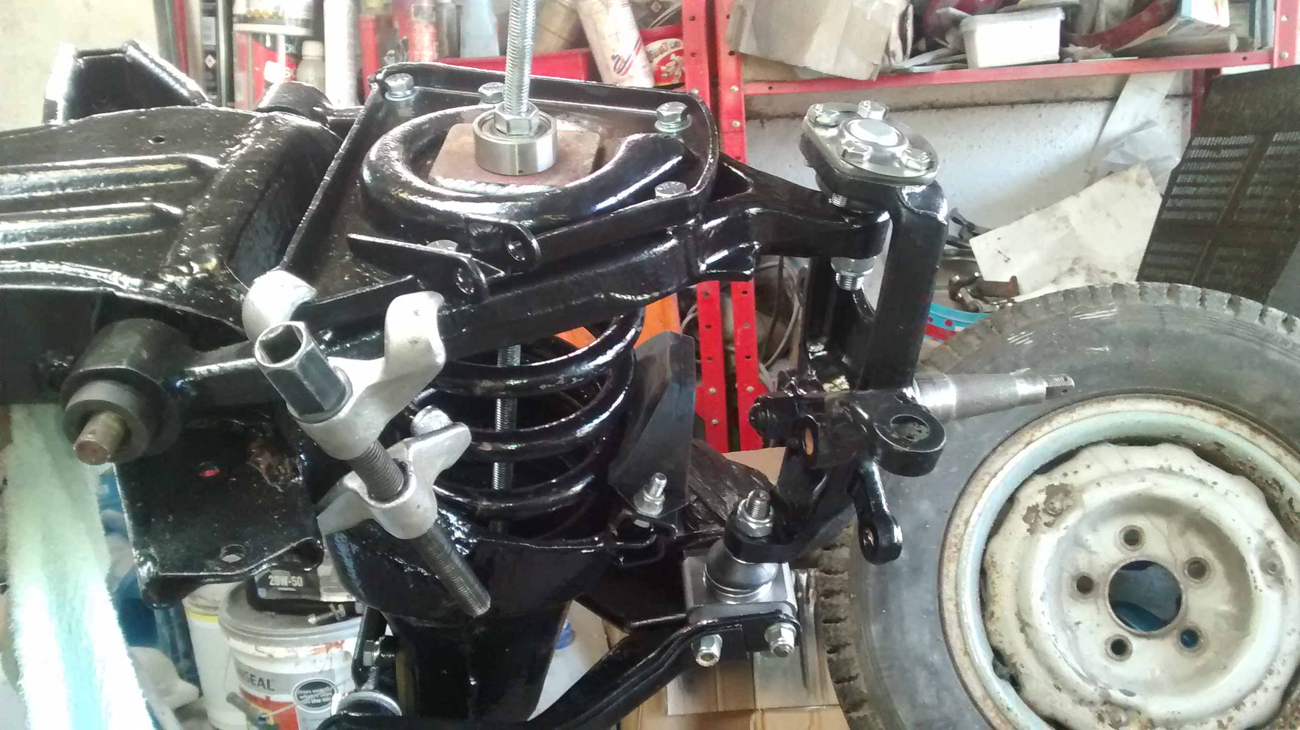
I have installed the front springs this weekend, I did this a piece of M12 all thread which wasn't really strong enough, I found afterwards that there is a piece which you can remove from the top shock absorber mount (it looks like a spring washer but flat) and I could have used a larger rod (probably M16).
I had to resort to using a coil spring compressor on one side of the spring pan to straighten it.
I've now found that one of the holes for the steering idler on the subframe has a stripped thread, I might helicoil it or I might drill it out and weld a nut, i'm not sure yet.
I had to resort to using a coil spring compressor on one side of the spring pan to straighten it.
I've now found that one of the holes for the steering idler on the subframe has a stripped thread, I might helicoil it or I might drill it out and weld a nut, i'm not sure yet.

Senior Member
littlelic69
Senior Member
close
Jul 25, 2024
- Join DateJan 2013
- LocationChester UK
- Posts:892
-
Likes:615
-
Liked:139 Times in 102 Posts
I also used a long threaded bar with some hefty washers/undulates when I did mine some years ago. As I recall, the threads became quite hot with all the effort put into turning the nuts. I used two on either end just in case!
I bought a helicoil kit and rethreaded the damaged mounting for the steering idler.
The sub-frame is now installed and i've started to fit the brakes, the drivers side is done and the passenger side is left to do.
As the steering quite hard to turn from the hub I have rebushed the column and am going to refit the steering mechanism to make it easier to turn the hub to do the other brake.
The lower column has a rubber coupling with four bolts, within the coupling are four aluminium sections which the bolts pass through however the holes in these on the original mounting were counter sunk into the coupling. On the new coupling only two of the holes are counter sunk and not as far as the original mounting, I have modified the new coupling by drilling these down to match the existing mounting.
Does anyone know why the old mounting might be different to the new one, is it a poor reproduction or do later cars have the mounting like this?
On another note, i'm still looking into rebuiling the servo, I can't find anyone who can supply the seals for the piston does anyone know where I can find these preferably in the UK? The main problem seems to be the rope seal around the piston.

Senior Member
csbush
Senior Member
close
Feb 12, 2024
- Join DateOct 2015
- LocationSan Antonio
- Posts:809
-
Likes:503
-
Liked:223 Times in 127 Posts
Thanks for the pictures and updates. I will be doing the same thing in the future, and it helps hear about what challenges you face with this.

Veteran Member
TilleyJon
Veteran Member
close
Sep 6, 2024
- Join DateJun 2016
- LocationBath UK
- Posts:1,656
-
Likes:173
-
Liked:438 Times in 364 Posts
Quote:
I had to resort to using a coil spring compressor on one side of the spring pan to straighten it.
It is usually easier to fit the wishbone, and compress the spring with the seat separate, you can then insert 3 long bolts through the seat into the wishbones when there is less compression on the spring, this will guide the seat into position and should avoid the twisting you experienced.Originally Posted by Homersimpson
I have installed the front springs this weekend, I did this a piece of M12 all thread which wasn't really strong enough, I found afterwards that there is a piece which you can remove from the top shock absorber mount (it looks like a spring washer but flat) and I could have used a larger rod (probably M16).I had to resort to using a coil spring compressor on one side of the spring pan to straighten it.
Which part did you have the issue with the difference in countersink etc. do you have a part number ? It is always a good resource here if there are issues with modern replacements and how people resolved them.
Nice job, keep up the good work, I must get round to posting my resto, I always enjoy reading others experiences, and it is such a great resource for us lunatics out there that take this on.
Quote:
Which part did you have the issue with the difference in countersink etc. do you have a part number ? It is always a good resource here if there are issues with modern replacements and how people resolved them.
Nice job, keep up the good work, I must get round to posting my resto, I always enjoy reading others experiences, and it is such a great resource for us lunatics out there that take this on.
Thanks for the tip, hopefully I wont have to get these out again in a hurry Originally Posted by TilleyJon
It is usually easier to fit the wishbone, and compress the spring with the seat separate, you can then insert 3 long bolts through the seat into the wishbones when there is less compression on the spring, this will guide the seat into position and should avoid the twisting you experienced.Which part did you have the issue with the difference in countersink etc. do you have a part number ? It is always a good resource here if there are issues with modern replacements and how people resolved them.
Nice job, keep up the good work, I must get round to posting my resto, I always enjoy reading others experiences, and it is such a great resource for us lunatics out there that take this on.
The part which I had to modify for the steering was part number C16432.
Veteran Member
TilleyJon
Veteran Member
close
Sep 6, 2024
- Join DateJun 2016
- LocationBath UK
- Posts:1,656
-
Likes:173
-
Liked:438 Times in 364 Posts
Quote:

The part which I had to modify for the steering was part number C16432.
The new doughnut is a newer version and should be fitted with Allen headed bolts, I assume that 2 are countersunk on one side and the other 2 are countersunk on the other side indicating that 2 Allen headed bolts should be fitted from one side and the other 2 from the other side, with thier heads sitting in the countersink.Originally Posted by Homersimpson
Thanks for the tip, hopefully I wont have to get these out again in a hurry The part which I had to modify for the steering was part number C16432.
The original bolts are UFS so they are a setscrew, and the heads would be bigger, that is why they specify new bolts with the new coupling.
I hope this sheds some light on this.
Quote:
The original bolts are UFS so they are a setscrew, and the heads would be bigger, that is why they specify new bolts with the new coupling.
I hope this sheds some light on this.
The replacement joint was only counter sunk on one side and these weren't as deep as the original.Originally Posted by TilleyJon
The new doughnut is a newer version and should be fitted with Allen headed bolts, I assume that 2 are countersunk on one side and the other 2 are countersunk on the other side indicating that 2 Allen headed bolts should be fitted from one side and the other 2 from the other side, with thier heads sitting in the countersink.The original bolts are UFS so they are a setscrew, and the heads would be bigger, that is why they specify new bolts with the new coupling.
I hope this sheds some light on this.
I modified this to match the original joint so I could fit the correct cap head bolts on both sides.
Veteran Member
TilleyJon
Veteran Member
close
Sep 6, 2024
- Join DateJun 2016
- LocationBath UK
- Posts:1,656
-
Likes:173
-
Liked:438 Times in 364 Posts
Quote:
I modified this to match the original joint so I could fit the correct cap head bolts on both sides.
That sounds like an error, did you get the parts from SNG ?Originally Posted by Homersimpson
The replacement joint was only counter sunk on one side and these weren't as deep as the original.I modified this to match the original joint so I could fit the correct cap head bolts on both sides.
I guess that 2 of the bolts are not really long enough if there is no countersink for them to go into ?
Looking at SNG, they state that 4 No C10838/1 are required which are 1 3/4" and longer than the C10838 which are 1 1/2", I was wrong about the setscrew, the original was the C10838 which is 1/1/2" long.
It makes no sense why only 2 would be countersunk on the new part, it may be worth checking with the supplier as this does appear incorrect somewhere.
I'm trying to fit the speedo cable but unfortunately none of the pictures I took at strip down give me any indication.
Is anyone able to give any indication of the cable route, its a RHD automatic.
Is anyone able to give any indication of the cable route, its a RHD automatic.
Veteran Member
TilleyJon
Veteran Member
close
Sep 6, 2024
- Join DateJun 2016
- LocationBath UK
- Posts:1,656
-
Likes:173
-
Liked:438 Times in 364 Posts
take a look at this
Engine fixings - Jaguar Mk2 Restoration
The speedo routes through the bottom hole on the left hand side of the firewall viewing from the front, the wiper cable (hard tube) through the top hole, the bunch of cables that feed thermo carb, oil pressure sender etc, through the second hole down, and the bonnet catch cable through the third hole. The cable then goes down the side of the pedal box, goes behind the clip to the left of the steering column and then follows the chassis leg to the back of the gearbox. The route is not cast in stone, but ensure the route is a straight as possible. (Avoid sharp bends)
Quote:
Engine fixings - Jaguar Mk2 Restoration
The speedo routes through the middle on the left hand side of the firewall viewing from the front, the wiper cable (hard tube) through the top hole and the bonnet catch cable through the bottom hole. The cable then goes down the side of the pedal box and follow the chassis leg to the back of the gearbox. The route is not cast in stone, but ensure the route is a straight as possible. (Avoid sharp bends)
Thanks for the reply, the first bit of the route is great but the car pictured is a manual and mines an auto with the speedo output on the other side of the gearbox, I think the cable goes over the top of the gearbox but I can't remember for sure.Originally Posted by TilleyJon
take a look at thisEngine fixings - Jaguar Mk2 Restoration
The speedo routes through the middle on the left hand side of the firewall viewing from the front, the wiper cable (hard tube) through the top hole and the bonnet catch cable through the bottom hole. The cable then goes down the side of the pedal box and follow the chassis leg to the back of the gearbox. The route is not cast in stone, but ensure the route is a straight as possible. (Avoid sharp bends)
Veteran Member
TilleyJon
Veteran Member
close
Sep 6, 2024
- Join DateJun 2016
- LocationBath UK
- Posts:1,656
-
Likes:173
-
Liked:438 Times in 364 Posts
Quote:
Originally Posted by Homersimpson
Thanks for the reply, the first bit of the route is great but the car pictured is a manual and mines an auto with the speedo output on the other side of the gearbox, I think the cable goes over the top of the gearbox but I can't remember for sure.
Is your gearbox the early DG box then ? It would either go over the gearbox or across the gearbox mounting I guess, I don't know that box at all. The route should be the straightest, and therefore will depend on whether the speedo output is on the top or bottom on the side.
Others with this setup may be able to give you a definite answer, sorry I cant be more help.
Veteran Member
TilleyJon
Veteran Member
close
Sep 6, 2024
- Join DateJun 2016
- LocationBath UK
- Posts:1,656
-
Likes:173
-
Liked:438 Times in 364 Posts
Homersimpson.
Did you find the solution to Speedo cable route, check out https://www.jaguarforums.com/forum/m...outing-173049/ for the same question, the answer will come up somewhere
Jon
Did you find the solution to Speedo cable route, check out https://www.jaguarforums.com/forum/m...outing-173049/ for the same question, the answer will come up somewhere
Jon
I've bought a new battery for the car and cranked it over a few times with the plugs out to bring the oil pressure up but the engine was having none of it.
I didn't want to keep trying so I looked into priming the oil system, in the end I removed the oil pressure switch, connected a pipe to this and then connected this to a bolt filled with engine oil (I used an empty gear oil bottle with the pipe outlet for this).
I hung the bottle over the engine and left it over night and it emptied (and collapsed the bottle!), I then did this again the next night.
The next day I removed the bottle, fitted a mechanical pressure gauge and cranked it over and the oil pressure came up to around 20PSI on the starter.
I then fitted the plugs and turned it over and it started straight away, oil pressure is around 50PSI when cold and drops to around 25PSI at idle when warm.
The engine sounds really good, i'm very pleased and its given me a good boost to the project.
I'm now fitting the new wiring loom.
Senior Member
csbush
Senior Member
close
Feb 12, 2024
- Join DateOct 2015
- LocationSan Antonio
- Posts:809
-
Likes:503
-
Liked:223 Times in 127 Posts
Congratulations on getting the engine running. That is a big milestone. You are really making great progress with your car. I was looking at your ruminations from earlier posts, and you must be very happy to have all that behind you, as well as a fresh engine that is ready to go
Hi All,
Its been a while since I last updated the thread about the car, I bled the brakes last week but I have had a slight issue where two of the bleed valves appeared to leak even after they were tightened.
I have removed them and replaced with the originals which seemed to do the same.
I have reinstalled the new ones and tightened them even tighter and it apperars to have stopped but i'm not happy with how tight they are.
Rather stangely one of the leaking valves was on a new reproduction slave cylinder and the other was on a rebuilt original.
Has anyone else experienced this, i've never had any bleed valves leak before and on an automatic car with single circuit brakes its rather concerning!
They seem to be leaking past the threads now I tightened them but originally they were leaking through the centre.
Either way the sealing surface is the base of the bleed screw so there shouldn't be any oil in this location to leak past surely?
Either way the sealing surface is the base of the bleed screw so there shouldn't be any oil in this location to leak past surely?